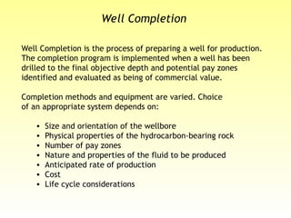
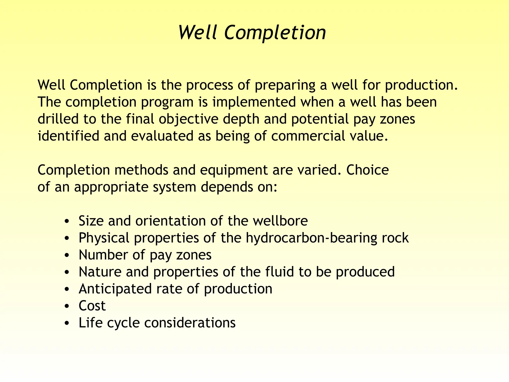
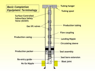
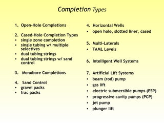
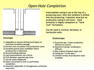
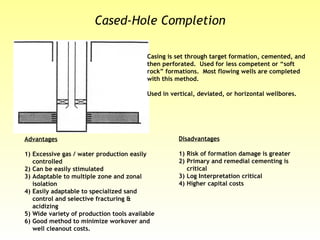
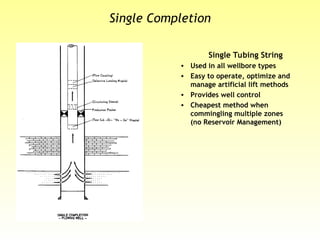
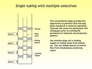
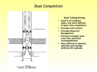
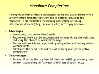
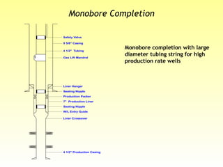
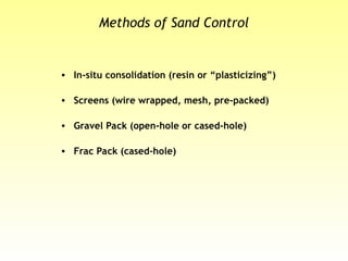
Well Completion
Well Completion is the process of preparing a well for production.
The completion program is implemented when a well has been
drilled to the final objective depth and potential pay zones
identified and evaluated as being of commercial value.
Completion methods and equipment are varied. Choice
of an appropriate system depends on:
• Size and orientation of the wellbore
• Physical properties of the hydrocarbon-bearing rock
• Number of pay zones
• Nature and properties of the fluid to be produced
• Anticipated rate of production
• Cost
• Life cycle considerations
Basic Completion
Equipment Terminology
Tubing hanger
Tubing spool
Surface Controlled
Subsurface Safety
Valve (SCSSV)
Gas lift valves
Production casing
Production packer
No Go Nipple
Re-entry guide
Blast joint
Seal bore extension
Seal assembly
Production tubing
Flow coupling
Landing Nipple
Circulating sleeve
Completion Types
1. Open-Hole Completions
2. Cased-Hole Completion Types
• single zone completion
• single tubing w/ multiple
selectives
• dual tubing strings
• dual tubing strings w/ sand
control
3. Monobore Completions
4. Sand Control
• gravel packs
• frac packs
4. Horizontal Wells
• open hole, slotted liner, cased
5. Multi-Laterals
• TAML Levels
6. Intelligent Well Systems
7. Artificial Lift Systems
• beam (rod) pump
• gas lift
• electric submersible pumps (ESP)
• progressive cavity pumps (PCP)
• jet pump
• plunger lift
Open-Hole Completion
Intermediate casing is set at the top of a
producing zone, then the wellbore is drilled
into the producing / injection zone but no
production casing is set lower. Used
primarily in highly competent or “hard
rock” formations.
Can be used in vertical, deviated, or
horizontal wells.
Advantages
1) Adaptable to special drilling techniques to
minimize formation damage.
2) Prevent lost circulation into production zone.
3) Excellent gravel pack candidate where
productivity is important.
4) No perforating expense.
5) Log interpretations not critical.
6) Full diameter opposite pay zone.
7) Can be easily deepened.
8) Easily converted to liner or perforated
completion.
9) Generally applicable in homogeneous carbonate
reservoirs.
Disadvantages
1) Excessive gas / water production
difficult to control.
2) Selective fracing / acidizing is
difficult.
3) May require frequent clean out.
4) Casing set “in the dark.”
5) Limited variety of production tools
available.
Casing is set through target formation, cemented, and
then perforated. Used for less competent or “soft
rock” formations. Most flowing wells are completed
with this method.
Used in vertical, deviated, or horizontal wellbores.
Advantages
1) Excessive gas / water production easily
controlled
2) Can be easily stimulated
3) Adaptable to multiple zone and zonal
isolation
4) Easily adaptable to specialized sand
control and selective fracturing &
acidizing
5) Wide variety of production tools available
6) Good method to minimize workover and
well cleanout costs.
Disadvantages
1) Risk of formation damage is greater
2) Primary and remedial cementing is
critical
3) Log Interpretation critical
4) Higher capital costs
Cased-Hole Completion
Single Completion
Single Tubing String
• Used in all wellbore types
• Easy to operate, optimize and
manage artificial lift methods
• Provides well control
• Cheapest method when
commingling multiple zones
(no Reservoir Management)
Single tubing with multiple selectives
This conventional single provides the
opportunity to perform slick line plug
backs instead of a workover operation.
Typically the zones are perforated with
casing guns prior to running the
permanent or hydraulic set production
packers.
Use wireline plugs set in landing
nipples to isolate zones from bottom
up. Can use sliding sleeves to control
flow from simultaneous producing
zones.
Zone C
Zone A
Zone D
Zone B
Packer
Sliding
sleeve
Landing
nipple
Blast
joint
Dual Completion
Dual Tubing String
• Used in all wellbore
types, but more difficult
in open hole completions
• Provides well control
• Provides Reservoir
Management
• Prevents multiple zone
cross flow and fluid
incompatibilities
• More difficult to operate,
optimize and manage
artificial lift methods
Dual Tubing String Conventional
Two tubing strings that may or may not be the same size
provide a dual cash flow. Gas lift is more difficult to apply to a
dual and workover frequency & costs are typically higher in a
dual than a single or single selective.
Dual Tubing Strings with Gravel Packed Zones
This design combines the sand control method with the
previously mentioned issues of dual tubing strings. Another
method would be similar to the single selective to only gravel
pack one of the zones. Note that only the lower zone can be
accessed for through tubing repair work.
Dual Tubing String
Monobore Completions
A completion that utilizes a production tubing and casing string with a
uniform inside diameter (ID) from top to bottom, including the
formation. This facilitates the running and setting of tubing
intervention devices (plug, pack-offs, etc.) across pay intervals.
• Advantages
– Lower cost than conventional wells
– Future well work can be accomplished without killing the well, thus
reducing the chance of reservoir damage
– Future well work is accomplished by using either coil tubing and/or
wireline units
– Eliminates the need, risk and cost of stacking multiple selective
completions
• Disadvantages
– Smaller ID across the pay interval limits remedial options (e.g. sand
control, abandoning perfs, water and/or gas shut-off, etc.)
Monobore Completion
Monobore completion with large
diameter tubing string for high
production rate wells
Safety Valve
Seating Nipple
4 1/2" Tubing
Gas Lift Mandrel
9 5/8" Casing
Production Packer
7" Production Liner
4 1/2" Production Casing
Seating Nipple
W/L Entry Guide
Liner Crossover
Liner Hanger
Methods of Sand Control
• In-situ consolidation (resin or “plasticizing”)
• Screens (wire wrapped, mesh, pre-packed)
• Gravel Pack (open-hole or cased-hole)
• Frac Pack (cased-hole)
Resin Consolidation
• Inject resin
• Below frac pressure
• Zone coverage
• Limits
– short intervals
– small rathole
– coiled tubing placement
is best method
Formation Resin
Casing
Area
Gravel Pack Placement
Open-Hole:
Fill the Screen/Openhole
Annulus
Gravel Pack Placement
Cased-Hole:
• Fill screen/casing annulus
• Pack the perforation tunnels
Hydraulic Fracturing (stimulation)
• Improves flow path into the
wellbore
• Redistribute the stresses
• Lower the velocity of the
reservoir fluids... lessening
migration of fines
Damaged
Area
Damaged
Area
Borehole
Hydraulic Fracturing (stimualtion)
• Improves flow path into
the wellbore.
• Connect layers to the
wellbore.
• Redistribute the stresses.
• Lower the velocity of the
reservoir fluids...
lessening migration of
fines.
Horizontal Wells
A “horizontal well” or high angle well describes a well drilled
at an angle greater than 70º relative to vertical.
• Can connect natural fractures in carbonates.
• Prevent water/gas coning by reducing pressure draw down.
• Improves sweep efficiency through infill drilling, horizontal
injection for waterflood or EOR.
• Can enhance property value by increasing recovery in tight
gas reservoirs or thin sands or low permeability reservoirs.
• Location constraints limiting numerous wells.
Horizontal Open-Hole Completions
– Advantages:
• Higher Productivity
• Delay Water Production (shorten field life)
• Less Susceptible to Completion Damage
• Reduce number of wellbores for reserves recovery
• Lower Completion Cost
– Disadvantages:
• Difficult to Isolate Extraneous Fluid Production
• Multi-Zone Completions More Difficult
• Exposed shale intervals can cause problems
Horizontal Well Open-hole
Reservoir characteristics that
favor this completion
• Vertical permeability greater
than 50% horizontal
permeability
• No inter-bed barriers or
sealing laminations
• Stable formation or plan for
sand control
• Good bottom water control
• Confined surface and
reservoir access
• Fracture treatments possible,
but difficult
Reservoir characteristics that favor
this completion
• Vertical permeability greater
than 50% horizontal
permeability
• No inter-bed barriers or sealing
laminations
• Some sand production or plan
sand control
• Limited bottom water control
• Confined surface and reservoir
access
• No fracture treatments
Horizontal Well Open-Hole with Slotted Liner
Multi-Lateral Wellbores
• Reservoir Characteristics that
favor this completion
– Surface/reservoir access
limited
– Thick layer pay zones
– Multiple well types needed
– Compartmentalized reservoirs
– Wellbore placement needed
for sweep/drainage
– Limited access for future work
Drivers of Multilateral Technology
• Cost reduction
• Slot conservation
• Increased reserves
• Accelerated reserves
• Delineation of the reservoir
Intelligent Well Systems (IWS)
An Intelligent Well System is defined by ChevronTexaco
to include at least one downhole flow control valve, one
downhole sensor, and two distinct intervals.
Provides real-time reservoir management:
• Downhole data sensing, acquisition, and transmission
of temperature, pressure, density, flow, etc.
• Remote control of flow and well operations
Beam Pump (sucker-rod pump)
Mechanics
• Utilizes a reciprocating rod to move a
downhole pump.
• Downhole pump consists of “traveling”
and “standing” valves, which utilize
check valves to trap and mechanically
lift a column of fluid.
Characteristics
• Comprised ± 80% of all artificial lift.
• Predominantly land use.
• Handles gas and solids fairly well.
• Best for low-volume producers (5 to
5,000 BFPD)
Gas Lift
Mechanics
• Best mimics “natural” flow. Utilizes
pressurized gas injection downhole to lighten
the hydrostatic “head” of a column of fluid,
allowing reservoir pressure to lift the fluid
column to surface.
• Uses downhole valves to regulate the amount
and depth of gas injection
• Continuous or intermittent lift.
Characteristics
• Used wherever a gas source is available.
• Second most common lift system (Most
common offshore lift system).
• Good handling of solids.
• Wide range of production rates
Electric Submersible Pump (ESP)
Mechanics
• Utilizes a downhole electric motor to drive a
downhole centrifugal pump.
• Uses surface electrical transformers and
variable frequency speed drives to deliver
consistent power.
Characteristics
• Requires electrical power supply.
• Highest lift efficiency of all lift systems.
Becoming more common as an offshore lift
system.
• Poor handling of solids and fair handling of
gas.
• Wide range of production rates (200 to
30,000 BFPD)
• Lifespans anywhere from 1 to 7 years
depending on environment and
horsepower/power quality.

Section 5 - Well Completion for drilling .ppt

  • 1.
    Well Completion Well Completionis the process of preparing a well for production. The completion program is implemented when a well has been drilled to the final objective depth and potential pay zones identified and evaluated as being of commercial value. Completion methods and equipment are varied. Choice of an appropriate system depends on: • Size and orientation of the wellbore • Physical properties of the hydrocarbon-bearing rock • Number of pay zones • Nature and properties of the fluid to be produced • Anticipated rate of production • Cost • Life cycle considerations
  • 2.
    Basic Completion Equipment Terminology Tubinghanger Tubing spool Surface Controlled Subsurface Safety Valve (SCSSV) Gas lift valves Production casing Production packer No Go Nipple Re-entry guide Blast joint Seal bore extension Seal assembly Production tubing Flow coupling Landing Nipple Circulating sleeve
  • 3.
    Completion Types 1. Open-HoleCompletions 2. Cased-Hole Completion Types • single zone completion • single tubing w/ multiple selectives • dual tubing strings • dual tubing strings w/ sand control 3. Monobore Completions 4. Sand Control • gravel packs • frac packs 4. Horizontal Wells • open hole, slotted liner, cased 5. Multi-Laterals • TAML Levels 6. Intelligent Well Systems 7. Artificial Lift Systems • beam (rod) pump • gas lift • electric submersible pumps (ESP) • progressive cavity pumps (PCP) • jet pump • plunger lift
  • 4.
    Open-Hole Completion Intermediate casingis set at the top of a producing zone, then the wellbore is drilled into the producing / injection zone but no production casing is set lower. Used primarily in highly competent or “hard rock” formations. Can be used in vertical, deviated, or horizontal wells. Advantages 1) Adaptable to special drilling techniques to minimize formation damage. 2) Prevent lost circulation into production zone. 3) Excellent gravel pack candidate where productivity is important. 4) No perforating expense. 5) Log interpretations not critical. 6) Full diameter opposite pay zone. 7) Can be easily deepened. 8) Easily converted to liner or perforated completion. 9) Generally applicable in homogeneous carbonate reservoirs. Disadvantages 1) Excessive gas / water production difficult to control. 2) Selective fracing / acidizing is difficult. 3) May require frequent clean out. 4) Casing set “in the dark.” 5) Limited variety of production tools available.
  • 5.
    Casing is setthrough target formation, cemented, and then perforated. Used for less competent or “soft rock” formations. Most flowing wells are completed with this method. Used in vertical, deviated, or horizontal wellbores. Advantages 1) Excessive gas / water production easily controlled 2) Can be easily stimulated 3) Adaptable to multiple zone and zonal isolation 4) Easily adaptable to specialized sand control and selective fracturing & acidizing 5) Wide variety of production tools available 6) Good method to minimize workover and well cleanout costs. Disadvantages 1) Risk of formation damage is greater 2) Primary and remedial cementing is critical 3) Log Interpretation critical 4) Higher capital costs Cased-Hole Completion
  • 6.
    Single Completion Single TubingString • Used in all wellbore types • Easy to operate, optimize and manage artificial lift methods • Provides well control • Cheapest method when commingling multiple zones (no Reservoir Management)
  • 7.
    Single tubing withmultiple selectives This conventional single provides the opportunity to perform slick line plug backs instead of a workover operation. Typically the zones are perforated with casing guns prior to running the permanent or hydraulic set production packers. Use wireline plugs set in landing nipples to isolate zones from bottom up. Can use sliding sleeves to control flow from simultaneous producing zones. Zone C Zone A Zone D Zone B Packer Sliding sleeve Landing nipple Blast joint
  • 8.
    Dual Completion Dual TubingString • Used in all wellbore types, but more difficult in open hole completions • Provides well control • Provides Reservoir Management • Prevents multiple zone cross flow and fluid incompatibilities • More difficult to operate, optimize and manage artificial lift methods
  • 9.
    Dual Tubing StringConventional Two tubing strings that may or may not be the same size provide a dual cash flow. Gas lift is more difficult to apply to a dual and workover frequency & costs are typically higher in a dual than a single or single selective. Dual Tubing Strings with Gravel Packed Zones This design combines the sand control method with the previously mentioned issues of dual tubing strings. Another method would be similar to the single selective to only gravel pack one of the zones. Note that only the lower zone can be accessed for through tubing repair work. Dual Tubing String
  • 10.
    Monobore Completions A completionthat utilizes a production tubing and casing string with a uniform inside diameter (ID) from top to bottom, including the formation. This facilitates the running and setting of tubing intervention devices (plug, pack-offs, etc.) across pay intervals. • Advantages – Lower cost than conventional wells – Future well work can be accomplished without killing the well, thus reducing the chance of reservoir damage – Future well work is accomplished by using either coil tubing and/or wireline units – Eliminates the need, risk and cost of stacking multiple selective completions • Disadvantages – Smaller ID across the pay interval limits remedial options (e.g. sand control, abandoning perfs, water and/or gas shut-off, etc.)
  • 11.
    Monobore Completion Monobore completionwith large diameter tubing string for high production rate wells Safety Valve Seating Nipple 4 1/2" Tubing Gas Lift Mandrel 9 5/8" Casing Production Packer 7" Production Liner 4 1/2" Production Casing Seating Nipple W/L Entry Guide Liner Crossover Liner Hanger
  • 12.
    Methods of SandControl • In-situ consolidation (resin or “plasticizing”) • Screens (wire wrapped, mesh, pre-packed) • Gravel Pack (open-hole or cased-hole) • Frac Pack (cased-hole)
  • 13.
    Resin Consolidation • Injectresin • Below frac pressure • Zone coverage • Limits – short intervals – small rathole – coiled tubing placement is best method Formation Resin Casing Area
  • 14.
    Gravel Pack Placement Open-Hole: Fillthe Screen/Openhole Annulus
  • 15.
    Gravel Pack Placement Cased-Hole: •Fill screen/casing annulus • Pack the perforation tunnels
  • 16.
    Hydraulic Fracturing (stimulation) •Improves flow path into the wellbore • Redistribute the stresses • Lower the velocity of the reservoir fluids... lessening migration of fines Damaged Area Damaged Area Borehole
  • 17.
    Hydraulic Fracturing (stimualtion) •Improves flow path into the wellbore. • Connect layers to the wellbore. • Redistribute the stresses. • Lower the velocity of the reservoir fluids... lessening migration of fines.
  • 18.
    Horizontal Wells A “horizontalwell” or high angle well describes a well drilled at an angle greater than 70º relative to vertical. • Can connect natural fractures in carbonates. • Prevent water/gas coning by reducing pressure draw down. • Improves sweep efficiency through infill drilling, horizontal injection for waterflood or EOR. • Can enhance property value by increasing recovery in tight gas reservoirs or thin sands or low permeability reservoirs. • Location constraints limiting numerous wells.
  • 19.
    Horizontal Open-Hole Completions –Advantages: • Higher Productivity • Delay Water Production (shorten field life) • Less Susceptible to Completion Damage • Reduce number of wellbores for reserves recovery • Lower Completion Cost – Disadvantages: • Difficult to Isolate Extraneous Fluid Production • Multi-Zone Completions More Difficult • Exposed shale intervals can cause problems
  • 20.
    Horizontal Well Open-hole Reservoircharacteristics that favor this completion • Vertical permeability greater than 50% horizontal permeability • No inter-bed barriers or sealing laminations • Stable formation or plan for sand control • Good bottom water control • Confined surface and reservoir access • Fracture treatments possible, but difficult
  • 21.
    Reservoir characteristics thatfavor this completion • Vertical permeability greater than 50% horizontal permeability • No inter-bed barriers or sealing laminations • Some sand production or plan sand control • Limited bottom water control • Confined surface and reservoir access • No fracture treatments Horizontal Well Open-Hole with Slotted Liner
  • 22.
    Multi-Lateral Wellbores • ReservoirCharacteristics that favor this completion – Surface/reservoir access limited – Thick layer pay zones – Multiple well types needed – Compartmentalized reservoirs – Wellbore placement needed for sweep/drainage – Limited access for future work
  • 23.
    Drivers of MultilateralTechnology • Cost reduction • Slot conservation • Increased reserves • Accelerated reserves • Delineation of the reservoir
  • 24.
    Intelligent Well Systems(IWS) An Intelligent Well System is defined by ChevronTexaco to include at least one downhole flow control valve, one downhole sensor, and two distinct intervals. Provides real-time reservoir management: • Downhole data sensing, acquisition, and transmission of temperature, pressure, density, flow, etc. • Remote control of flow and well operations
  • 25.
    Beam Pump (sucker-rodpump) Mechanics • Utilizes a reciprocating rod to move a downhole pump. • Downhole pump consists of “traveling” and “standing” valves, which utilize check valves to trap and mechanically lift a column of fluid. Characteristics • Comprised ± 80% of all artificial lift. • Predominantly land use. • Handles gas and solids fairly well. • Best for low-volume producers (5 to 5,000 BFPD)
  • 26.
    Gas Lift Mechanics • Bestmimics “natural” flow. Utilizes pressurized gas injection downhole to lighten the hydrostatic “head” of a column of fluid, allowing reservoir pressure to lift the fluid column to surface. • Uses downhole valves to regulate the amount and depth of gas injection • Continuous or intermittent lift. Characteristics • Used wherever a gas source is available. • Second most common lift system (Most common offshore lift system). • Good handling of solids. • Wide range of production rates
  • 27.
    Electric Submersible Pump(ESP) Mechanics • Utilizes a downhole electric motor to drive a downhole centrifugal pump. • Uses surface electrical transformers and variable frequency speed drives to deliver consistent power. Characteristics • Requires electrical power supply. • Highest lift efficiency of all lift systems. Becoming more common as an offshore lift system. • Poor handling of solids and fair handling of gas. • Wide range of production rates (200 to 30,000 BFPD) • Lifespans anywhere from 1 to 7 years depending on environment and horsepower/power quality.

Editor's Notes

  • #28 Cost Reduction The purpose of the technology is to reduce CAPEX. The idea is simply to incur only the cost of rig time, tools, services, and equipment needed to drill and complete an average deviated lateral of 300-1500 feet. The costs of mobilization/ demobilization, casing, and drilling to top of zone will essentially be borne by the main wellbore. A possible cost reduction scenario would have the multilateral well providing twice the production, but only 1.5 times the cost of a monobore completion.
  • #30 Geometry of Multi-lateral and Multi-Branched Wells Generally the following naming convention is used to describe the well geometry of multi-lateral wells <configuration> <number of laterals> The well configuration may be described as ‘stacked’, ‘planar’ or ‘opposed’. For more complex configurations a physical description may be used e.g. ‘Y-well’ or ‘herring bone’. The number of laterals may be described as dual-lateral, tri-lateral, quadrilateral etc. Table 2.1 contains some of the well configurations that are possible in multilateral and multibranch drilling.