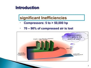
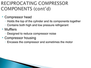
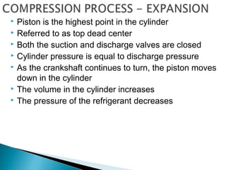
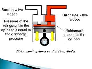
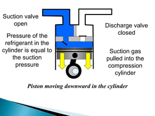
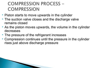
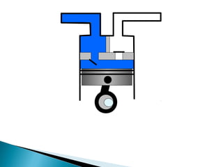
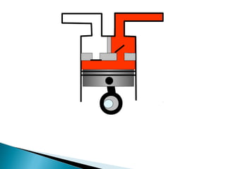
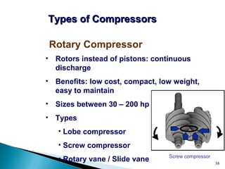
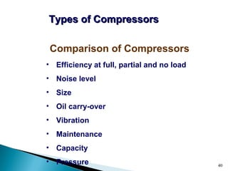
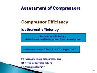
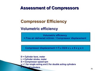
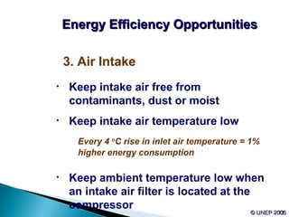
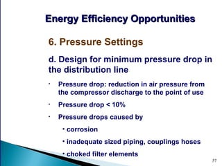
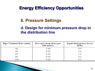
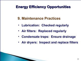
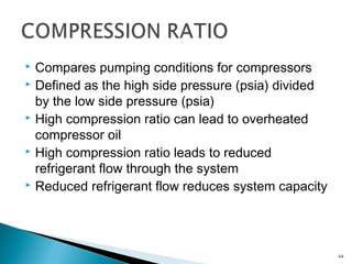
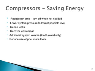
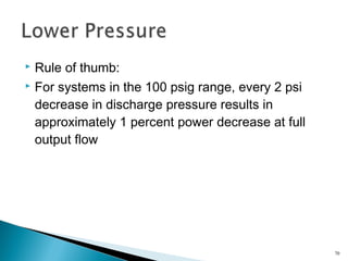
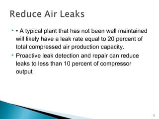
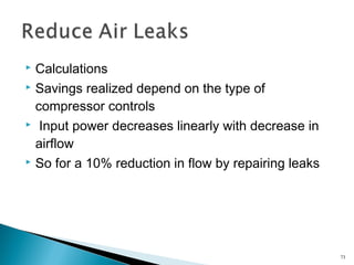
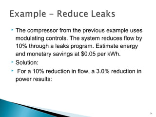
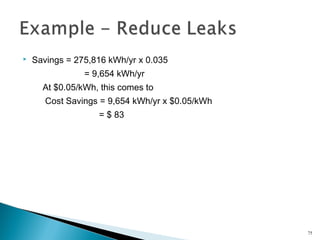
1
.
2
Compressors &Compressors &
Compressed AirCompressed Air
SystemsSystems
 an instrument or device for compressing
something.
 a machine used to supply air or other gas at
increased pressure, e.g. to power a gas turbine.
 an electrical device which reduces the dynamic
range of a sound signal.
3
4
CompressorCompressor
Introduction
Types of compressors
Assessment of compressors and
compressed air systems
Energy efficiency opportunities
5
• Compressors: 5 to > 50,000 hp
• 70 – 90% of compressed air is lost
significant Inefficiencies
IntroductionIntroduction
6
• Electricity savings: 20 – 50%
• Maintenance reduced, downtime decreased,
production increased and product quality
improved
Benefits of managed system
IntroductionIntroduction
7
• Intake air filters
• Inter-stage coolers
• After coolers
• Air dryers
• Moisture drain traps
• Receivers
Main Components in Compressed
Air Systems
IntroductionIntroduction
8
CompressorCompressor
Introduction
Types of compressors
Assessment of compressors and
compressed air systems
Energy efficiency opportunities
9
Two Basic Compressor Types
Types of CompressorsTypes of Compressors
Type of
compressor
Positive
displacement
Dynamic
Reciprocating Rotary Centrifugal Axial
10
• Used for air and refrigerant compression
• Works like a bicycle pump: cylinder volume reduces
while pressure increases, with pulsating output
• Many configurations available
• Single acting when using one side of the piston, and
double acting when using both sides
Reciprocating Compressor
Types of CompressorsTypes of Compressors
11
 Sub type of Reciprocating
◦ Fully welded, hermetic compressors
◦ Semi-hermetic compressors
◦ Open-drive compressors
◦ Belt-driven and direct-drive compressors
12
 Motor and compressor contained in a welded shell
 Cannot be field serviced
 Typically a “throw-away” compressor
 Considered to be a low-side component
 Cooled by suction gas from the evaporator
 Lubricated by the splash method
 Bolted together, can be field serviced
 Housing is made of cast iron
 Has a horizontal crankshaft
 Smaller compressors are splash lubricated
 Larger compressors use pressure lubrication systems
 Often air cooled
 Piston heads are located at the top of the compressor
 Motor pulley is called the drive pulley
 Compressor pulley is called the driven pulley
 Pulleys can be adjusted to change compressor speed
 Drive size x Drive rpm = Driven size x Driven rpm
 Shafts must be properly aligned
 Pulleys with multiple grooves must used matched sets
of belts
 Direct drive compressors turn at the
same speed as the motor used
 Motor shaft and compressor shaft must
be perfectly aligned end to end
 Motor shaft and compressor shafts are
joined with a flexible coupling
 Crankshaft
◦ Transfers motor motion to the piston
◦ Creates the back and forth motion of the piston
 Connecting rods
◦ Connects the crankshaft to the pistons
 Pistons
◦ Slide up and down in the cylinder
◦ Used to compress and expand the refrigerant
 Refrigerant cylinder valves (suction)
◦ Durable, flexible steel
◦ Located on the bottom of the valve plate
◦ Open when refrigerant is introduced to the pump
 Refrigerant cylinder valves (discharge)
◦ Durable, flexible steel
◦ Open when refrigerant is discharged from the pump
◦ Located on the top of the valve plate
Suction line Discharge line
Valve plate
Head Discharge valve
Suction valve Piston
Rings
CrankshaftConnecting Rod
 Compressor head
◦ Holds the top of the cylinder and its components together
◦ Contains both high and low pressure refrigerant
 Mufflers
◦ Designed to reduce compressor noise
 Compressor housing
◦ Encases the compressor and sometimes the motor
 Determined by initial compressor design
 Four processes take place during the compression
process
◦ Expansion (re-expansion)
◦ Suction (Intake)
◦ Compression
◦ Discharge
 Piston is the highest point in the cylinder
 Referred to as top dead center
 Both the suction and discharge valves are closed
 Cylinder pressure is equal to discharge pressure
 As the crankshaft continues to turn, the piston moves
down in the cylinder
 The volume in the cylinder increases
 The pressure of the refrigerant decreases
Suction valve
closed Discharge valve
closed
Piston moving downward in the cylinder
Refrigerant
trapped in the
cylinder
Pressure of the
refrigerant in the
cylinder is equal to
the discharge
pressure
 As the piston moves down, the pressure decreases
 When the cylinder pressure falls below suction pressure,
the suction valve opens
 The discharge valve remains in the closed position
 As the piston continues downward, vapor from the
suction line is pulled into the cylinder
 Suction continues until the piston reaches the lowest
position in the cylinder (bottom dead center)
 At the bottom of the stroke, suction valves close
Suction valve
open Discharge valve
closed
Piston moving downward in the cylinder
Pressure of the
refrigerant in the
cylinder is equal to
the suction
pressure
Suction gas
pulled into the
compression
cylinder
 Piston starts to move upwards in the cylinder
 The suction valve closes and the discharge valve
remains closed
 As the piston moves upwards, the volume in the cylinder
decreases
 The pressure of the refrigerant increases
 Compression continues until the pressure in the cylinder
rises just above discharge pressure
Suction valve
closed Discharge valve
closed
Piston moving up in the cylinder
Pressure of the
refrigerant in the
cylinder is equal to
the suction
pressure
Volume is
decreasing,
compressing the
refrigerant
 When the cylinder pressure rises above discharge
pressure, the discharge valve opens and the suction
valve remains closed
 As the piston continues to move upwards, the refrigerant
is discharged from the compressor
 Discharge continues until the piston reaches top dead
center
Suction valve
open Discharge valve
closed
Piston moving up in the cylinder
Pressure of the
refrigerant in the
cylinder is equal to
the discharge
pressure
Discharge gas
pushed from the
compression
cylinder
38
Screw compressor
• Rotors instead of pistons: continuous
discharge
• Benefits: low cost, compact, low weight,
easy to maintain
• Sizes between 30 – 200 hp
• Types
• Lobe compressor
• Screw compressor
• Rotary vane / Slide vane
Rotary Compressor
Types of CompressorsTypes of Compressors
39
• Rotating impeller
transfers energy
to move air
• Continuous duty
Centrifugal Compressor
Types of CompressorsTypes of Compressors
• Designed oil
free
• High volume
applications
> 12,000 cfm
40
• Efficiency at full, partial and no load
• Noise level
• Size
• Oil carry-over
• Vibration
• Maintenance
• Capacity
• Pressure
Comparison of Compressors
Types of CompressorsTypes of Compressors
41
CompressorCompressor
Introduction
Types of compressors
Assessment of compressors and
compressed air systems
Energy efficiency opportunities
42
• Capacity: full rated volume of flow of
compressed gas
• Actual flow rate: free air delivery (FAD)
• FAD reduced by ageing, poor maintenance,
fouled heat exchanger and altitude
• Energy loss: percentage deviation of FAD
capacity
Capacity of a Compressor
Assessment of CompressorsAssessment of Compressors
43
• Isolate compressor and receiver and close receiver
outlet
• Empty the receiver and the pipeline from water
• Start the compressor and activate the stopwatch
• Note time taken to attain the normal operational
pressure P2 (in the receiver) from initial pressure P1
Simple Capacity Assessment Method
Assessment of CompressorsAssessment of Compressors
44
Compressor Efficiency
Assessment of CompressorsAssessment of Compressors
• Most practical: specific power
consumption (kW / volume flow rate)
• Other methods
• Isothermal
• Volumetric
• Adiabatic
• Mechanical
45
Isothermal efficiency
P1 = Absolute intake pressure kg / cm2
Q1 = Free air delivered m3 / hr
r = Pressure ratio P2/P1
Compressor Efficiency
Assessment of CompressorsAssessment of Compressors
Isothermal efficiency =
Actual measured input power / Isothermal power
Isothermal power (kW) = P1 x Q1 x loger / 36.7
46
Volumetric efficiency
D = Cylinder bore, meter
L = Cylinder stroke, meter
S = Compressor speed rpm
χ = 1 for single acting and 2 for double acting cylinders
n = No. of cylinders
Compressor Efficiency
Assessment of CompressorsAssessment of Compressors
Volumetric efficiency
= Free air delivered m3/min / Compressor displacement
Compressor displacement = Π x D2/4 x L x S x χ x n
47
• Consequences
• Energy waste: 20 – 30% of output
• Drop in system pressure
• Shorter equipment life
• Common leakage areas
• Couplings, hoses, tubes, fittings
• Pressure regulators
• Open condensate traps, shut-off valves
• Pipe joints, disconnects, thread sealants
Leaks
Assessment of CompressorsAssessment of Compressors
48
• Total leakage calculation:
T = on-load time (minutes)
t = off-load time (minutes)
• Well maintained system: less than 10%
leakages
Leak Quantification Method
Assessment of CompressorsAssessment of Compressors
Leakage (%) = [(T x 100) / (T + t)]
49
• Shut off compressed air operated equipments
• Run compressor to charge the system to set
pressure of operation
• Note the time taken for “Load” and “Unload”
cycles
• Calculate quantity of leakage (previous slide)
• If Q is actual free air supplied during trial
(m3/min), then:
Quantifying leaks on the shop floor
Assessment of CompressorsAssessment of Compressors
System leakage (m3/minute) = Q × T / (T + t)
50
: Compressor: Compressor
Introduction
Types of compressors
Assessment of compressors and
compressed air systems
Energy efficiency opportunities
51
• Significant influence on energy use
Energy Efficiency OpportunitiesEnergy Efficiency Opportunities
1. Location
2. Elevation
• Higher altitude = lower volumetric
efficiency
52© UNEP 2006© UNEP 2006
3. Air Intake
• Keep intake air free from
contaminants, dust or moist
• Keep intake air temperature low
Every 4 o
C rise in inlet air temperature = 1%
higher energy consumption
• Keep ambient temperature low when
an intake air filter is located at the
compressor
Energy Efficiency OpportunitiesEnergy Efficiency Opportunities
53
4. Pressure Drops in Air Filter
• Install filter in cool location or draw
air from cool location
• Keep pressure drop across intake air
filter to a minimum
Every 250 mm WC pressure drop =
2% higher energy consumption
Energy Efficiency OpportunitiesEnergy Efficiency Opportunities
54
5. Use Inter and After Coolers
• Inlet air temperature rises at each
stage of multi-stage machine
• Inter coolers: heat exchangers that
remove heat between stages
• After coolers: reduce air temperature
after final stage
• Use water at lower temperature:
reduce power
Energy Efficiency OpportunitiesEnergy Efficiency Opportunities
55
• Higher pressure
• More power by compressors
• Lower volumetric efficiency
• Operating above operating pressures
• Waste of energy
• Excessive wear
Energy Efficiency OpportunitiesEnergy Efficiency Opportunities
6. Pressure Settings
56
a. Reducing delivery pressure
Operating a compressor at 120 PSIG instead of 100
PSIG: 10% less energy and reduced leakage rate
Energy Efficiency OpportunitiesEnergy Efficiency Opportunities
6. Pressure Settings
b. Compressor modulation by optimum
pressure settings
Applicable when different compressors connected
c. Segregating high/low pressure
requirements
Pressure reducing valves no longer needed
57
d. Design for minimum pressure drop in
the distribution line
• Pressure drop: reduction in air pressure from
the compressor discharge to the point of use
• Pressure drop < 10%
• Pressure drops caused by
• corrosion
• inadequate sized piping, couplings hoses
• choked filter elements
Energy Efficiency OpportunitiesEnergy Efficiency Opportunities
6. Pressure Settings
58
d. Design for minimum pressure drop in
the distribution line
Energy Efficiency OpportunitiesEnergy Efficiency Opportunities
6. Pressure Settings
59
7. Minimizing Leakage
• Use ultrasonic acoustic detector
• Tighten joints and connections
• Replace faulty equipment
8. Condensate Removal
• Condensate formed as after-cooler reduces
discharge air temperature
• Install condensate separator trap to remove
condensate
Energy Efficiency OpportunitiesEnergy Efficiency Opportunities
60
9. Controlled usage
• Do not use for low-pressure
applications: agitation, combustion air,
pneumatic conveying
• Use blowers instead
10. Compressor controls
• Automatically turns off compressor
when not needed
Energy Efficiency OpportunitiesEnergy Efficiency Opportunities
61
9. Maintenance Practices
• Lubrication: Checked regularly
• Air filters: Replaced regularly
• Condensate traps: Ensure drainage
• Air dryers: Inspect and replace filters
Energy Efficiency OpportunitiesEnergy Efficiency Opportunities
62
 Considered the heart of the refrigeration
systems
 Compressors are vapor pumps
 Responsible for lowering the pressure on the
suction side of the system
 Responsible for increasing the pressure on the
discharge side of the system
 Suction gas from the evaporator enters the
compressor
 Refrigerant is discharged to the condenser
63
 Compares pumping conditions for compressors
 Defined as the high side pressure (psia) divided
by the low side pressure (psia)
 High compression ratio can lead to overheated
compressor oil
 High compression ratio leads to reduced
refrigerant flow through the system
 Reduced refrigerant flow reduces system capacity
64
 R-12 compressor
◦ 169 psig high side, 2 psig low side
◦ 183.7 psia high side, 16.7 psia low side
◦ 183.7 psia ÷ 16.7 psia = 11:1 compression ratio
 R-134a compressor
◦ 184.6 psig high side, 0.7 in. Hg. vacuum low side
◦ 199.3 psia high side, 14.35 psia low side
◦ 199.3 psia ÷ 14.35 psia = 13.89:1 compression
ratio
65
 Scroll compressors
 compress the air using two spiral elements. 1 is stationary, and the
other one moves in small eccentric circles inside the other spiral. Air
gets trapped and because of the way the spirals move, gets
transported in small air-pockets to the center of the spiral. It takes
about 2.5 turn for the air to reach the pressure output in the center.
66
 Very quiet. Really very quiet!
 Compact. A scroll compressor is very small.
 Simple design, not so many parts
 Low maintenance (hardly any)
 Oil-free design
67
 Low capacity (flow, liters/minute or cfpm).
 Relatively expensive
 When the scroll-element fails, there’s a very big chance you just
have to buy a whole new element.
 The compressed air gets very hot! Much hotter than compared to
other types of compressors
68
 Reduce run time – turn off when not needed
 Lower system pressure to lowest possible level
 Repair leaks
 Recover waste heat
 Additional system volume (load/unload only)
 Reduce use of pneumatic tools
69
 Rule of thumb:
 For systems in the 100 psig range, every 2 psi
decrease in discharge pressure results in
approximately 1 percent power decrease at full
output flow
70
 • Rule of thumb:
 For systems with 30 to 50 percent unregulated
usage, a 2 psi decrease in header pressure will
decrease energy consumption by about 0.6 to 1.0
percent because of unregulated air
 Total is 1.6% to 2% power decrease for every 2
psi drop
71
 • A typical plant that has not been well maintained
will likely have a leak rate equal to 20 percent of
total compressed air production capacity.
 Proactive leak detection and repair can reduce
leaks to less than 10 percent of compressor
output
72
 Calculations
 Savings realized depend on the type of
compressor controls
 Input power decreases linearly with decrease in
airflow
 So for a 10% reduction in flow by repairing leaks
73
 The compressor from the previous example uses
modulating controls. The system reduces flow by
10% through a leaks program. Estimate energy
and monetary savings at $0.05 per kWh.
 Solution:
 For a 10% reduction in flow, a 3.0% reduction in
power results:
74
 Savings = 275,816 kWh/yr x 0.035
= 9,654 kWh/yr
At $0.05/kWh, this comes to
Cost Savings = 9,654 kWh/yr x $0.05/kWh
= $ 83
75
 Routinely check v-belts for proper tightness
because loose belts can reduce compressor
efficiency.
76
 If liquid enters the cylinder, damage will occur
 Liquids cannot be compressed
 Liquid slugging can cause immediate damage to the
compressor components
 Common causes of liquid slugging include an
overfeeding metering device, poor evaporator air
circulation, low heat load, defective evaporator fan
motor and a frosted evaporator coil
 High suction pressures and low discharge pressures
keep the compression ratio low
 Dirty evaporators cause suction pressure to drop
 Low suction reduces compressor pumping capacity
 Dirty condensers increase head pressure
 Compression ratio is increased by dirty or blocked
condenser and evaporator coils
79
 We offer a broad array of products, including a full range of rotary
and reciprocating air compressors from ½ to 200 horsepower. We
serve the compressed air needs of many industries such as the
following:
 Oil and gas
 Light industry
 Automotive
 Marine
 HVAC
 Medical
 Food and beverage
80
81

Refrigeration

  • 1.
  • 2.
    2 Compressors &Compressors & CompressedAirCompressed Air SystemsSystems
  • 3.
     an instrumentor device for compressing something.  a machine used to supply air or other gas at increased pressure, e.g. to power a gas turbine.  an electrical device which reduces the dynamic range of a sound signal. 3
  • 4.
    4 CompressorCompressor Introduction Types of compressors Assessmentof compressors and compressed air systems Energy efficiency opportunities
  • 5.
    5 • Compressors: 5to > 50,000 hp • 70 – 90% of compressed air is lost significant Inefficiencies IntroductionIntroduction
  • 6.
    6 • Electricity savings:20 – 50% • Maintenance reduced, downtime decreased, production increased and product quality improved Benefits of managed system IntroductionIntroduction
  • 7.
    7 • Intake airfilters • Inter-stage coolers • After coolers • Air dryers • Moisture drain traps • Receivers Main Components in Compressed Air Systems IntroductionIntroduction
  • 8.
    8 CompressorCompressor Introduction Types of compressors Assessmentof compressors and compressed air systems Energy efficiency opportunities
  • 9.
    9 Two Basic CompressorTypes Types of CompressorsTypes of Compressors Type of compressor Positive displacement Dynamic Reciprocating Rotary Centrifugal Axial
  • 10.
    10 • Used forair and refrigerant compression • Works like a bicycle pump: cylinder volume reduces while pressure increases, with pulsating output • Many configurations available • Single acting when using one side of the piston, and double acting when using both sides Reciprocating Compressor Types of CompressorsTypes of Compressors
  • 11.
  • 12.
     Sub typeof Reciprocating ◦ Fully welded, hermetic compressors ◦ Semi-hermetic compressors ◦ Open-drive compressors ◦ Belt-driven and direct-drive compressors 12
  • 13.
     Motor andcompressor contained in a welded shell  Cannot be field serviced  Typically a “throw-away” compressor  Considered to be a low-side component  Cooled by suction gas from the evaporator  Lubricated by the splash method
  • 14.
     Bolted together,can be field serviced  Housing is made of cast iron  Has a horizontal crankshaft  Smaller compressors are splash lubricated  Larger compressors use pressure lubrication systems  Often air cooled  Piston heads are located at the top of the compressor
  • 15.
     Motor pulleyis called the drive pulley  Compressor pulley is called the driven pulley  Pulleys can be adjusted to change compressor speed  Drive size x Drive rpm = Driven size x Driven rpm  Shafts must be properly aligned  Pulleys with multiple grooves must used matched sets of belts
  • 16.
     Direct drivecompressors turn at the same speed as the motor used  Motor shaft and compressor shaft must be perfectly aligned end to end  Motor shaft and compressor shafts are joined with a flexible coupling
  • 17.
     Crankshaft ◦ Transfersmotor motion to the piston ◦ Creates the back and forth motion of the piston  Connecting rods ◦ Connects the crankshaft to the pistons  Pistons ◦ Slide up and down in the cylinder ◦ Used to compress and expand the refrigerant
  • 18.
     Refrigerant cylindervalves (suction) ◦ Durable, flexible steel ◦ Located on the bottom of the valve plate ◦ Open when refrigerant is introduced to the pump  Refrigerant cylinder valves (discharge) ◦ Durable, flexible steel ◦ Open when refrigerant is discharged from the pump ◦ Located on the top of the valve plate
  • 19.
    Suction line Dischargeline Valve plate Head Discharge valve Suction valve Piston Rings CrankshaftConnecting Rod
  • 20.
     Compressor head ◦Holds the top of the cylinder and its components together ◦ Contains both high and low pressure refrigerant  Mufflers ◦ Designed to reduce compressor noise  Compressor housing ◦ Encases the compressor and sometimes the motor
  • 21.
     Determined byinitial compressor design  Four processes take place during the compression process ◦ Expansion (re-expansion) ◦ Suction (Intake) ◦ Compression ◦ Discharge
  • 22.
     Piston isthe highest point in the cylinder  Referred to as top dead center  Both the suction and discharge valves are closed  Cylinder pressure is equal to discharge pressure  As the crankshaft continues to turn, the piston moves down in the cylinder  The volume in the cylinder increases  The pressure of the refrigerant decreases
  • 23.
    Suction valve closed Dischargevalve closed Piston moving downward in the cylinder Refrigerant trapped in the cylinder Pressure of the refrigerant in the cylinder is equal to the discharge pressure
  • 24.
     As thepiston moves down, the pressure decreases  When the cylinder pressure falls below suction pressure, the suction valve opens  The discharge valve remains in the closed position  As the piston continues downward, vapor from the suction line is pulled into the cylinder  Suction continues until the piston reaches the lowest position in the cylinder (bottom dead center)  At the bottom of the stroke, suction valves close
  • 25.
    Suction valve open Dischargevalve closed Piston moving downward in the cylinder Pressure of the refrigerant in the cylinder is equal to the suction pressure Suction gas pulled into the compression cylinder
  • 26.
     Piston startsto move upwards in the cylinder  The suction valve closes and the discharge valve remains closed  As the piston moves upwards, the volume in the cylinder decreases  The pressure of the refrigerant increases  Compression continues until the pressure in the cylinder rises just above discharge pressure
  • 27.
    Suction valve closed Dischargevalve closed Piston moving up in the cylinder Pressure of the refrigerant in the cylinder is equal to the suction pressure Volume is decreasing, compressing the refrigerant
  • 28.
     When thecylinder pressure rises above discharge pressure, the discharge valve opens and the suction valve remains closed  As the piston continues to move upwards, the refrigerant is discharged from the compressor  Discharge continues until the piston reaches top dead center
  • 29.
    Suction valve open Dischargevalve closed Piston moving up in the cylinder Pressure of the refrigerant in the cylinder is equal to the discharge pressure Discharge gas pushed from the compression cylinder
  • 38.
    38 Screw compressor • Rotorsinstead of pistons: continuous discharge • Benefits: low cost, compact, low weight, easy to maintain • Sizes between 30 – 200 hp • Types • Lobe compressor • Screw compressor • Rotary vane / Slide vane Rotary Compressor Types of CompressorsTypes of Compressors
  • 39.
    39 • Rotating impeller transfersenergy to move air • Continuous duty Centrifugal Compressor Types of CompressorsTypes of Compressors • Designed oil free • High volume applications > 12,000 cfm
  • 40.
    40 • Efficiency atfull, partial and no load • Noise level • Size • Oil carry-over • Vibration • Maintenance • Capacity • Pressure Comparison of Compressors Types of CompressorsTypes of Compressors
  • 41.
    41 CompressorCompressor Introduction Types of compressors Assessmentof compressors and compressed air systems Energy efficiency opportunities
  • 42.
    42 • Capacity: fullrated volume of flow of compressed gas • Actual flow rate: free air delivery (FAD) • FAD reduced by ageing, poor maintenance, fouled heat exchanger and altitude • Energy loss: percentage deviation of FAD capacity Capacity of a Compressor Assessment of CompressorsAssessment of Compressors
  • 43.
    43 • Isolate compressorand receiver and close receiver outlet • Empty the receiver and the pipeline from water • Start the compressor and activate the stopwatch • Note time taken to attain the normal operational pressure P2 (in the receiver) from initial pressure P1 Simple Capacity Assessment Method Assessment of CompressorsAssessment of Compressors
  • 44.
    44 Compressor Efficiency Assessment ofCompressorsAssessment of Compressors • Most practical: specific power consumption (kW / volume flow rate) • Other methods • Isothermal • Volumetric • Adiabatic • Mechanical
  • 45.
    45 Isothermal efficiency P1 =Absolute intake pressure kg / cm2 Q1 = Free air delivered m3 / hr r = Pressure ratio P2/P1 Compressor Efficiency Assessment of CompressorsAssessment of Compressors Isothermal efficiency = Actual measured input power / Isothermal power Isothermal power (kW) = P1 x Q1 x loger / 36.7
  • 46.
    46 Volumetric efficiency D =Cylinder bore, meter L = Cylinder stroke, meter S = Compressor speed rpm χ = 1 for single acting and 2 for double acting cylinders n = No. of cylinders Compressor Efficiency Assessment of CompressorsAssessment of Compressors Volumetric efficiency = Free air delivered m3/min / Compressor displacement Compressor displacement = Π x D2/4 x L x S x χ x n
  • 47.
    47 • Consequences • Energywaste: 20 – 30% of output • Drop in system pressure • Shorter equipment life • Common leakage areas • Couplings, hoses, tubes, fittings • Pressure regulators • Open condensate traps, shut-off valves • Pipe joints, disconnects, thread sealants Leaks Assessment of CompressorsAssessment of Compressors
  • 48.
    48 • Total leakagecalculation: T = on-load time (minutes) t = off-load time (minutes) • Well maintained system: less than 10% leakages Leak Quantification Method Assessment of CompressorsAssessment of Compressors Leakage (%) = [(T x 100) / (T + t)]
  • 49.
    49 • Shut offcompressed air operated equipments • Run compressor to charge the system to set pressure of operation • Note the time taken for “Load” and “Unload” cycles • Calculate quantity of leakage (previous slide) • If Q is actual free air supplied during trial (m3/min), then: Quantifying leaks on the shop floor Assessment of CompressorsAssessment of Compressors System leakage (m3/minute) = Q × T / (T + t)
  • 50.
    50 : Compressor: Compressor Introduction Typesof compressors Assessment of compressors and compressed air systems Energy efficiency opportunities
  • 51.
    51 • Significant influenceon energy use Energy Efficiency OpportunitiesEnergy Efficiency Opportunities 1. Location 2. Elevation • Higher altitude = lower volumetric efficiency
  • 52.
    52© UNEP 2006©UNEP 2006 3. Air Intake • Keep intake air free from contaminants, dust or moist • Keep intake air temperature low Every 4 o C rise in inlet air temperature = 1% higher energy consumption • Keep ambient temperature low when an intake air filter is located at the compressor Energy Efficiency OpportunitiesEnergy Efficiency Opportunities
  • 53.
    53 4. Pressure Dropsin Air Filter • Install filter in cool location or draw air from cool location • Keep pressure drop across intake air filter to a minimum Every 250 mm WC pressure drop = 2% higher energy consumption Energy Efficiency OpportunitiesEnergy Efficiency Opportunities
  • 54.
    54 5. Use Interand After Coolers • Inlet air temperature rises at each stage of multi-stage machine • Inter coolers: heat exchangers that remove heat between stages • After coolers: reduce air temperature after final stage • Use water at lower temperature: reduce power Energy Efficiency OpportunitiesEnergy Efficiency Opportunities
  • 55.
    55 • Higher pressure •More power by compressors • Lower volumetric efficiency • Operating above operating pressures • Waste of energy • Excessive wear Energy Efficiency OpportunitiesEnergy Efficiency Opportunities 6. Pressure Settings
  • 56.
    56 a. Reducing deliverypressure Operating a compressor at 120 PSIG instead of 100 PSIG: 10% less energy and reduced leakage rate Energy Efficiency OpportunitiesEnergy Efficiency Opportunities 6. Pressure Settings b. Compressor modulation by optimum pressure settings Applicable when different compressors connected c. Segregating high/low pressure requirements Pressure reducing valves no longer needed
  • 57.
    57 d. Design forminimum pressure drop in the distribution line • Pressure drop: reduction in air pressure from the compressor discharge to the point of use • Pressure drop < 10% • Pressure drops caused by • corrosion • inadequate sized piping, couplings hoses • choked filter elements Energy Efficiency OpportunitiesEnergy Efficiency Opportunities 6. Pressure Settings
  • 58.
    58 d. Design forminimum pressure drop in the distribution line Energy Efficiency OpportunitiesEnergy Efficiency Opportunities 6. Pressure Settings
  • 59.
    59 7. Minimizing Leakage •Use ultrasonic acoustic detector • Tighten joints and connections • Replace faulty equipment 8. Condensate Removal • Condensate formed as after-cooler reduces discharge air temperature • Install condensate separator trap to remove condensate Energy Efficiency OpportunitiesEnergy Efficiency Opportunities
  • 60.
    60 9. Controlled usage •Do not use for low-pressure applications: agitation, combustion air, pneumatic conveying • Use blowers instead 10. Compressor controls • Automatically turns off compressor when not needed Energy Efficiency OpportunitiesEnergy Efficiency Opportunities
  • 61.
    61 9. Maintenance Practices •Lubrication: Checked regularly • Air filters: Replaced regularly • Condensate traps: Ensure drainage • Air dryers: Inspect and replace filters Energy Efficiency OpportunitiesEnergy Efficiency Opportunities
  • 62.
  • 63.
     Considered theheart of the refrigeration systems  Compressors are vapor pumps  Responsible for lowering the pressure on the suction side of the system  Responsible for increasing the pressure on the discharge side of the system  Suction gas from the evaporator enters the compressor  Refrigerant is discharged to the condenser 63
  • 64.
     Compares pumpingconditions for compressors  Defined as the high side pressure (psia) divided by the low side pressure (psia)  High compression ratio can lead to overheated compressor oil  High compression ratio leads to reduced refrigerant flow through the system  Reduced refrigerant flow reduces system capacity 64
  • 65.
     R-12 compressor ◦169 psig high side, 2 psig low side ◦ 183.7 psia high side, 16.7 psia low side ◦ 183.7 psia ÷ 16.7 psia = 11:1 compression ratio  R-134a compressor ◦ 184.6 psig high side, 0.7 in. Hg. vacuum low side ◦ 199.3 psia high side, 14.35 psia low side ◦ 199.3 psia ÷ 14.35 psia = 13.89:1 compression ratio 65
  • 66.
     Scroll compressors  compressthe air using two spiral elements. 1 is stationary, and the other one moves in small eccentric circles inside the other spiral. Air gets trapped and because of the way the spirals move, gets transported in small air-pockets to the center of the spiral. It takes about 2.5 turn for the air to reach the pressure output in the center. 66
  • 67.
     Very quiet.Really very quiet!  Compact. A scroll compressor is very small.  Simple design, not so many parts  Low maintenance (hardly any)  Oil-free design 67
  • 68.
     Low capacity(flow, liters/minute or cfpm).  Relatively expensive  When the scroll-element fails, there’s a very big chance you just have to buy a whole new element.  The compressed air gets very hot! Much hotter than compared to other types of compressors 68
  • 69.
     Reduce runtime – turn off when not needed  Lower system pressure to lowest possible level  Repair leaks  Recover waste heat  Additional system volume (load/unload only)  Reduce use of pneumatic tools 69
  • 70.
     Rule ofthumb:  For systems in the 100 psig range, every 2 psi decrease in discharge pressure results in approximately 1 percent power decrease at full output flow 70
  • 71.
     • Ruleof thumb:  For systems with 30 to 50 percent unregulated usage, a 2 psi decrease in header pressure will decrease energy consumption by about 0.6 to 1.0 percent because of unregulated air  Total is 1.6% to 2% power decrease for every 2 psi drop 71
  • 72.
     • Atypical plant that has not been well maintained will likely have a leak rate equal to 20 percent of total compressed air production capacity.  Proactive leak detection and repair can reduce leaks to less than 10 percent of compressor output 72
  • 73.
     Calculations  Savingsrealized depend on the type of compressor controls  Input power decreases linearly with decrease in airflow  So for a 10% reduction in flow by repairing leaks 73
  • 74.
     The compressorfrom the previous example uses modulating controls. The system reduces flow by 10% through a leaks program. Estimate energy and monetary savings at $0.05 per kWh.  Solution:  For a 10% reduction in flow, a 3.0% reduction in power results: 74
  • 75.
     Savings =275,816 kWh/yr x 0.035 = 9,654 kWh/yr At $0.05/kWh, this comes to Cost Savings = 9,654 kWh/yr x $0.05/kWh = $ 83 75
  • 76.
     Routinely checkv-belts for proper tightness because loose belts can reduce compressor efficiency. 76
  • 77.
     If liquidenters the cylinder, damage will occur  Liquids cannot be compressed  Liquid slugging can cause immediate damage to the compressor components  Common causes of liquid slugging include an overfeeding metering device, poor evaporator air circulation, low heat load, defective evaporator fan motor and a frosted evaporator coil
  • 78.
     High suctionpressures and low discharge pressures keep the compression ratio low  Dirty evaporators cause suction pressure to drop  Low suction reduces compressor pumping capacity  Dirty condensers increase head pressure  Compression ratio is increased by dirty or blocked condenser and evaporator coils
  • 79.
  • 80.
     We offera broad array of products, including a full range of rotary and reciprocating air compressors from ½ to 200 horsepower. We serve the compressed air needs of many industries such as the following:  Oil and gas  Light industry  Automotive  Marine  HVAC  Medical  Food and beverage 80
  • 81.

Editor's Notes

  • #3 TO THE TRAINER This PowerPoint presentation can be used to train people about the basics of compressors and compressed air systems. The information on the slides is the minimum information that should be explained. The trainer notes for each slide provide more detailed information, but it is up to the trainer to decide if and how much of this information is presented also. Additional materials that can be used for the training session are available on www.energyefficiencyasia.org under “Energy Equipment” and include: Textbook chapter on this energy equipment that forms the basis of this PowerPoint presentation but has more detailed information Quiz – ten multiple choice questions that trainees can answer after the training session Workshop exercise – a practical calculation related to this equipment Option checklist – a list of the most important options to improve energy efficiency of this equipment Company case studies – participants of past courses have given the feedback that they would like to hear about options implemented at companies for each energy equipment. More than 200 examples are available from 44 companies in the cement, steel, chemicals, ceramics and pulp &amp; paper sectors
  • #5 This first section covers an introduction to compressors and compressed air systems.
  • #6 Industrial plants use compressed air throughout their production operations, which is produced by compressed air units ranging from 5 horsepower (hp) to over 50,000 hp. The US Department of Energy reports that 70 to 90 percent of compressed air is lost in the form of unusable heat, friction, misuse and noise. For this reason, compressors and compressed air systems are important areas to improve energy efficiency at industrial plants.
  • #7 It is worth noting that the running cost of a compressed air system is far higher than the cost of a compressor itself. Energy savings from system improvements can range from 20 to 50 percent or more of electricity consumption, resulting in thousands to hundreds of thousands of dollars. A properly managed compressed air system can save energy, reduce maintenance, decrease downtime, increase production throughput, and improve product quality
  • #8 Compressed air systems consist of following major components: Intake Air Filters that prevent dust from entering a compressor. Dust causes sticking valves, scoured cylinders, excessive wear etc. Inter-stage Coolers that reduce the temperature of the air before it enters the next stage to reduce the work of compression and increase efficiency. They are normally water-cooled. After-Coolers with the objective is to remove the moisture in the air by reducing the temperature in a water-cooled heat exchanger. Air-dryers that remove the remaining traces of moisture after after-cooler as equipment has to be relatively free of any moisture. Moisture drain traps that are used for removal of moisture in the compressed air. These traps resemble steam traps. Various types of traps used are manual drain cocks, timer based / automatic drain valves etc. Receivers that are provided as storage and smoothening pulsating air output - reducing pressure variations from the compressor
  • #9 Types of compressors.
  • #10 There are two basic compressor types: positive-displacement and dynamic. In the positive-displacement type, a given quantity of air or gas is trapped in a compression chamber and the volume it occupies is mechanically reduced, causing a corresponding rise in pressure prior to discharge. At constant speed, the air flow remains essentially constant with variations in discharge pressure. Dynamic compressors impart velocity energy to continuously flowing air or gas by means of impellers rotating at very high speeds. The velocity energy is changed into pressure energy both by the impellers and the discharge volutes or diffusers. In the centrifugal-type dynamic compressors, the shape of the impeller blades determines the relationship between air flow and the pressure (or head) generate We will now go through the various types of compressors.
  • #11 In industry, reciprocating compressors are the most widely used type for both air and refrigerant compression. They work on the principles of a bicycle pump and are characterized by a flow output that remains nearly constant over a range of discharge pressures. Also, the compressor capacity is directly proportional to the speed. The output, however, is a pulsating one. Reciprocating compressors are available in many configurations The four most widely used are horizontal, vertical, horizontal balance-opposed and tandem air-cooled or water-cooled lubricated and non-lubricated may be packaged provide a wide range of pressure and capacity selections. The reciprocating air compressor is considered single acting when the compressing is accomplished using only one side of the piston. A compressor using both sides of the piston is considered double acting.
  • #39 Rotary compressors have rotors in place of pistons and give a continuous pulsation free discharge. They operate at high speed and generally provide higher throughput than reciprocating compressors. Their capital costs are low, they are compact in size, have low weight, and are easy to maintain. For this reason they have gained popularity with industry. They are most commonly used in sizes from about 30 to 200 hp or 22 to 150 kW. Types of rotary compressors include: Lobe compressor, Screw compressor, Rotary vane / sliding-vane. The picture shows a screw compressor Rotary screw compressors may be air or water-cooled. Since the cooling takes place right inside the compressor, the working parts never experience extreme operating temperatures. The rotary compressor, therefore, is a continuous duty, air cooled or water cooled compressor package.
  • #40 The centrifugal air compressor is a dynamic compressor, which depends on transfer of energy from a rotating impeller to the air. The rotor accomplishes this by changing the momentum and pressure of the air. This momentum is converted to useful pressure by slowing the air down in a stationary diffuser. The centrifugal air compressor is an oil free compressor by design. The oil lubricated running gear is separated from the air by shaft seals and atmospheric vents. The centrifugal is a continuous duty compressor, with few moving parts, that is particularly suited to high volume applications-especially where oil free air is required. Centrifugal air compressors are water-cooled and may be packaged; typically the package includes the after-cooler and all controls. These compressors have appreciably different characteristics as compared to reciprocating machines. A small change in compression ratio produces a marked change in compressor output and efficiency. Centrifugal machines are better suited for applications requiring very high capacities, typically above 12,000 cfm (cubic feet per minute).
  • #41 These factors are important when selecting a compressor. The chapter includes a table comparing different compressors on these factors.
  • #42 Assessment of compressors and compressed air systems.
  • #43 The capacity of a compressor is the full rated volume of flow of gas compressed and delivered under conditions of total temperature, total pressure, and composition prevailing at the compressor inlet. It sometimes means actual flow rate, rather than rated volume of flow. This is also called free air delivery (FAD) i.e. air at atmospheric conditions at any specific location. This term does not mean air delivered under identical or standard conditions because the altitude, barometer, and temperature may vary at different localities and at different times. Due to ageing of the compressors and inherent inefficiencies in the internal components, the free air delivered may be less than the design value, despite good maintenance practices. Sometimes, other factors such as poor maintenance, fouled heat exchanger and effects of altitude also tend to reduce free air delivery. In order to meet the air demand, the inefficient compressor may have to run for more time, thus consuming more power than actually required. The power wastage depends on the percentage deviation of FAD capacity. For example, a worn out compressor valve can reduce the compressor capacity by as much as 20 percent. A periodic assessment of the FAD capacity of each compressor has to be carried out to check its actual capacity. If the deviations are more than 10 percent, corrective measures should be taken to rectify the same.
  • #44 We will go through how to perform a simple capacity assessment in a shop floor: Isolate the compressor along with its individual receiver that are to be taken for a test from the main compressed air system by tightly closing the isolation valve or blanking it, thus closing the receiver outlet. Open the water drain valve and drain out water fully and empty the receiver and the pipeline. Make sure that the water trap line is tightly closed once again to start the test. Start the compressor and activate the stopwatch. Note the time taken to attain the normal operational pressure P2 (in the receiver) from initial pressure P1. Calculate the capacity as per the formulae given. FAD is to be corrected by a factor (273 + t1) / (273 + t2)
  • #45 For practical purposes, the most effective guide in comparing compressor efficiencies is the specific power consumption, i.e. kW/volume flow rate, for different compressors that would provide identical duty. There are several different measures of compressor efficiency that are commonly used including volumetric efficiency, adiabatic efficiency, isothermal efficiency and mechanical efficiency. We will only discuss isothermal and volumetric efficiency calculation methods here
  • #46 The reported value of efficiency is normally the isothermal efficiency. This is an important consideration when selecting compressors based on reported values of efficiency. Isothermal efficiency is calculated as follows: Isothermal Efficiency=Actual measured input power / Isothermal Power Isothermal power (kW) = P1 x Q1 x loger/36.7 Where P1 = Absolute intake pressure kg/ cm2; Q1 = Free air delivered m3/hr; and r = Pressure ratio P2/P1. The calculation of isothermal power does not include power needed to overcome friction and generally gives an efficiency that is lower than adiabatic efficiency.
  • #47 Volumetric efficiency = Free air delivered m3/min / Compressor displacement Compressor Displacement = Π x D2/4 x L x S x χ x n Where D = Cylinder bore, meter; L = Cylinder stroke, meter; S = Compressor speed rpm; χ = 1 for single acting and 2 for double acting cylinders; and n = No. of cylinders
  • #48 A system of distribution pipes and regulators convey compressed air from the central compressor plant to process areas. This system includes various isolation valves, fluid traps, intermediate storage vessels, and even heat trace on pipes to prevent condensation or freezing in lines exposed to the outdoors. Pressure losses in distribution typically are compensated for by higher pressure at the compressor discharge. At the intended point of use, a feeder pipe with a final isolation valve, filter, and regulator carries the compressed air to hoses that supply processes or pneumatic tools. Leaks can be a significant source of wasted energy in an industrial compressed air system, sometimes wasting 20 to 30 percent of a compressor’s output. A typical plant that has not been well maintained will likely have a leak rate equal to 20 percent of total compressed air production capacity. On the other hand, proactive leak detection and repair can reduce leaks to less than 10 percent of compressor output. In addition to being a source of wasted energy, leaks can also contribute to other operating losses. Leaks cause a drop in system pressure, which can make air tools function less efficiently, adversely affecting production. In addition, by forcing the equipment to run longer, leaks shorten the life of almost all system equipment (including the compressor package itself). Increased running time can also lead to additional maintenance requirements and increased unscheduled downtime. Finally, leaks can lead to adding unnecessary compressor capacity. While leakage can come from any part of the system, the most common problem areas are: Couplings, hoses, tubes, and fittings Pressure regulators Open condensate traps and shut-off valves Pipe joints, disconnects, and thread sealants. Leakage rates are a function of the supply pressure in an uncontrolled system and increase with higher system pressures. Leakage rates identified in cubic feet per minute (cfm)
  • #49 For compressors that have start/stop or load/unload controls, there is an easy way to estimate the amount of leakage in the system. The method involves starting the compressor when there are no demands on the system. A number of measurements are taken to determine the average time it takes to load and unload the compressor. Total leakage in percentage can be calculated as: Leakage (%) = [(T x 199) / (T + t)], where T = on-load time, and t = off-load time. Leakage will be expressed in terms of the percentage of compressor capacity lost. The percentage lost to leakage should be less than 10per cent in a well maintained system. Poorly maintained systems can have losses as high as 20 to 30 percent of air capacity and power.
  • #50 This is a simple method to quantify leaks in a compressed air system. These are the steps: Shut off compressed air operated equipments (or conduct a test when no equipment is using compressed air). Run the compressor to charge the system to set pressure of operation Note the subsequent time taken for “Load” and “Unload” Cycles of the compressors. Use the above expression to find out the quantity of leakage in the system. If Q is the actual free air being supplied during trial then the system leakage would be: System leakage = Q × T / (T + t)
  • #51 Energy efficiency opportunities
  • #52 The location of air compressors and the quality of air drawn by the compressors will have a significant influence on the amount of energy consumed. Compressor performance as a breathing machine improves with cool, clean, dry air at intake Altitude has a direct impact on the volumetric efficiency of a compressor. The effect of altitude on volumetric efficiency is given in the Table 6. It is evident that compressors located at higher altitudes consume more power to achieve a particular delivery pressure than those at sea level, as the compression ratio is higher.
  • #53 The effect of intake air on compressor performance should not be underestimated. Intake air that is contaminated or hot can impair compressor performance and result in excess energy and maintenance costs. If moisture, dust, or other contaminants are present in the intake air. These contaminants can build up on the internal components of the compressor. The compressor generates heat due to its continuous operation. This heat gets dissipated to compressor chamber and leads to hot air intake. This results in lower volumetric efficiency and higher power consumption. As a general rule, “Every 40C rise in inlet air temperature results in a higher energy consumption by 1per cent to achieve equivalent output”. Hence cool air intake improves the energy efficiency of a compressor. When an intake air filter is located at the compressor, the ambient temperature should be kept to a minimum, to prevent reduction in mass flow. This can be accomplished by locating the inlet pipe outside the room or building. When the intake air filter is located outside the building, and particularly on a roof, ambient considerations may be taken into account.
  • #54 A compressor intake air filter should be installed in, or have air brought to it from a clean, cool location. The better the filtration at the compressor inlet, the lower the maintenance at the compressor. However, the pressure drop across the intake air filter should be kept to a minimum. The pressure drop across a new inlet filter should not exceed 3 pounds per square inch. As a general rule “For every 250 mm WC pressure drop increase across at the suction path due to choked filters etc, the compressor power consumption increases by about 2per cent for the same output” .
  • #55 Perfect cooling. Ideally, the temperature of the inlet air at each stage of a multi-stage machine should be the same as it was at the first stage. This is referred to as “perfect cooling” or isothermal compression. But in actual practice, the inlet air temperatures at subsequent stages are higher than the normal levels. Intercoolers. Most multi-stage compressors use intercoolers. These are heat exchangers that remove the heat of compression between the stages of compression. Intercooling affects the overall efficiency of the machine. After-coolers. As mechanical energy is applied to a gas for compression, the temperature of the gas increases. After-coolers are installed after the final stage of compression to reduce the air temperature. As the air temperature is reduced, water vapor in the air is condensed, separated, collected, and drained from the system. Use of water at lower temperature reduces specific power consumption. However, very low cooling water temperature could result in condensation of moisture in the air, which if not removed would lead to cylinder damage.
  • #56 For the same capacity, a compressor consumes more power at higher pressures. Subsequently, compressors should not be operated above their optimum operating pressures as this not only wastes energy, but also leads to excessive wear, leading to further energy wastage. The volumetric efficiency of a compressor is also less at higher delivery pressures.
  • #57 Reducing delivery pressure. The possibility of lowering and optimizing the delivery pressure settings should be explored by a careful study of pressure requirements. The operating of a compressed air system gently affects the cost of compressed air. Operating a compressor at 120 PSIG instead of 100 PSIG, for instance, requires 10 per cent more energy as well as increasing the leakage rate. Therefore, every effort should be made to reduce the system and compressor pressure to the lowest possible setting. (click once) Compressor modulation by optimum pressure settings. Very often in an industry, different types, capacities and makes of compressors are connected to a common distribution network. In such situations, proper selection of a right combination of compressors and optimal modulation of different compressors can conserve energy. For example, where more than one compressor feeds a common header, compressors have to be operated in such a way that the cost of compressed air generation is minimal. (click once) Segregating high and low pressure requirements. If the low-pressure air requirement is considerable, it is advisable to generate low pressure and high-pressure air separately and feed to the respective sections instead of reducing the pressure through pressure reducing valves, which invariably waste energy.
  • #58 Pressure drop is a term used to characterize the reduction in air pressure from the compressor discharge to the actual point-of-use. Pressure drop occurs as the compressed air travels through the treatment and distribution system. A properly designed system should have a pressure loss of much less than 10per cent of the compressor’s discharge pressure, measured from the receiver tank output to the point-of-use. The longer and smaller diameter the pipe is, the higher the friction loss. Pressure drops are caused by corrosion and the system components themselves are important issues. Excess pressure drop due to inadequate pipe sizing, choked filter elements, improperly sized couplings and hoses represent energy wastage.
  • #59 This table illustrates the energy wastage, if the pipes are of smaller diameter. Typical acceptable pressure drop in industrial practice is 0.3 bar in the mains header at the farthest point and 0.5 bar in distribution system.
  • #60 Minimizing leakage. Compressed air leakage accounts for substantial power wastage. The best way to detect leaks is to use an ultrasonic acoustic detector that can recognize the high-frequency hissing sounds associated with air leaks. Leaks occur most often at joints and connections. Stopping leaks can be as simple as tightening a connection or as complex as replacing faulty equipment. (click once) Condensate removal. After compressed air leaves the compression chamber the compressor’s after-cooler reduces the discharge air temperature well below the dew point. Therefore, considerable water vapor is condensed. To remove this condensation, most compressors with built-in after-coolers are furnished with a combination condensate separator-trap.
  • #61 Controlled usage. Since the compressed air system is already available, plant engineers may be tempted to use compressed air to provide air for low-pressure applications such as agitation, pneumatic conveying or combustion air. Using a blower that is designed for lower pressure operation will cost only a fraction of compressed air generation energy and cost. Note: in some companies, staff use compressed air to clean their clothes. Apart from the energy wastage, this is a very dangerous practice. Compressor controls. Air compressors become inefficient when they are operated at significantly below their rated cfm output. To avoid running extra air compressors when they are not needed, a controller can be installed to automatically turn compressors on and off, based on demand. Also, if the pressure of the compressed air system is kept as low as possible, efficiency improves and air leaks are reduced.
  • #62 Good and proper maintenance practices will dramatically improve the performance efficiency of a compressor system. Here are a few tips for efficient operation and maintenance of industrial compressed air systems: Lubrication: Compressor oil pressure should be visually checked daily, and the oil filter changed monthly. Air Filters: The inlet air filter can easily become clogged, particularly in dusty environments. Filters should be checked and replaced regularly. Condensate Traps: Many systems have condensate traps to gather flush condensate from the system. Manual traps should be periodically opened and re-closed to drain any accumulated fluid and automatic traps should be checked to verify they are not leaking compressed air. Air Dryers: Drying air is energy-intensive. For refrigerated dryers, inspect and replace pre-filters regularly as these dryers often have small internal passages that can become plugged with contaminants.