Downloaded 436 times

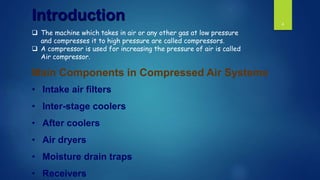
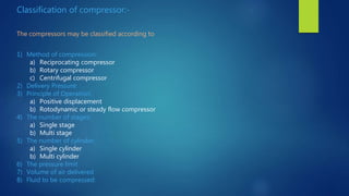
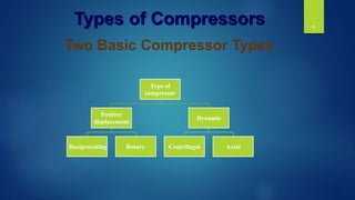
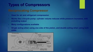
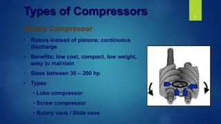
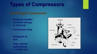
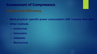
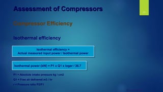

This document discusses different types of air compressors and components of compressed air systems. It describes the main types of compressors as positive displacement (reciprocating and rotary) and dynamic (centrifugal and axial). Reciprocating compressors use pistons to compress air in a pulsing manner, while rotary compressors use rotors for continuous compression. Centrifugal compressors use an impeller to transfer energy and compress large volumes of air continuously. The document also discusses assessing compressor efficiency using various metrics and identifies opportunities to improve energy efficiency such as reducing leaks, properly setting operating pressures, controlled usage, and implementing maintenance best practices.


![SBP- Air compressor [Compatibility Mode].pdf](https://cdn.slidesharecdn.com/ss_thumbnails/sbp-aircompressorcompatibilitymode-241227102120-b6a67cde-thumbnail.jpg?width=640&height=640&fit=bounds)


