Contents:-
⦿ Introduction ToCompressor
⦿ Classification Of Compressors
⦿ Screw Compressor
⦿ Conveying Air Compressor EG90W-5.5
⦿ Checking Efficiency Ƞ Of Compressor
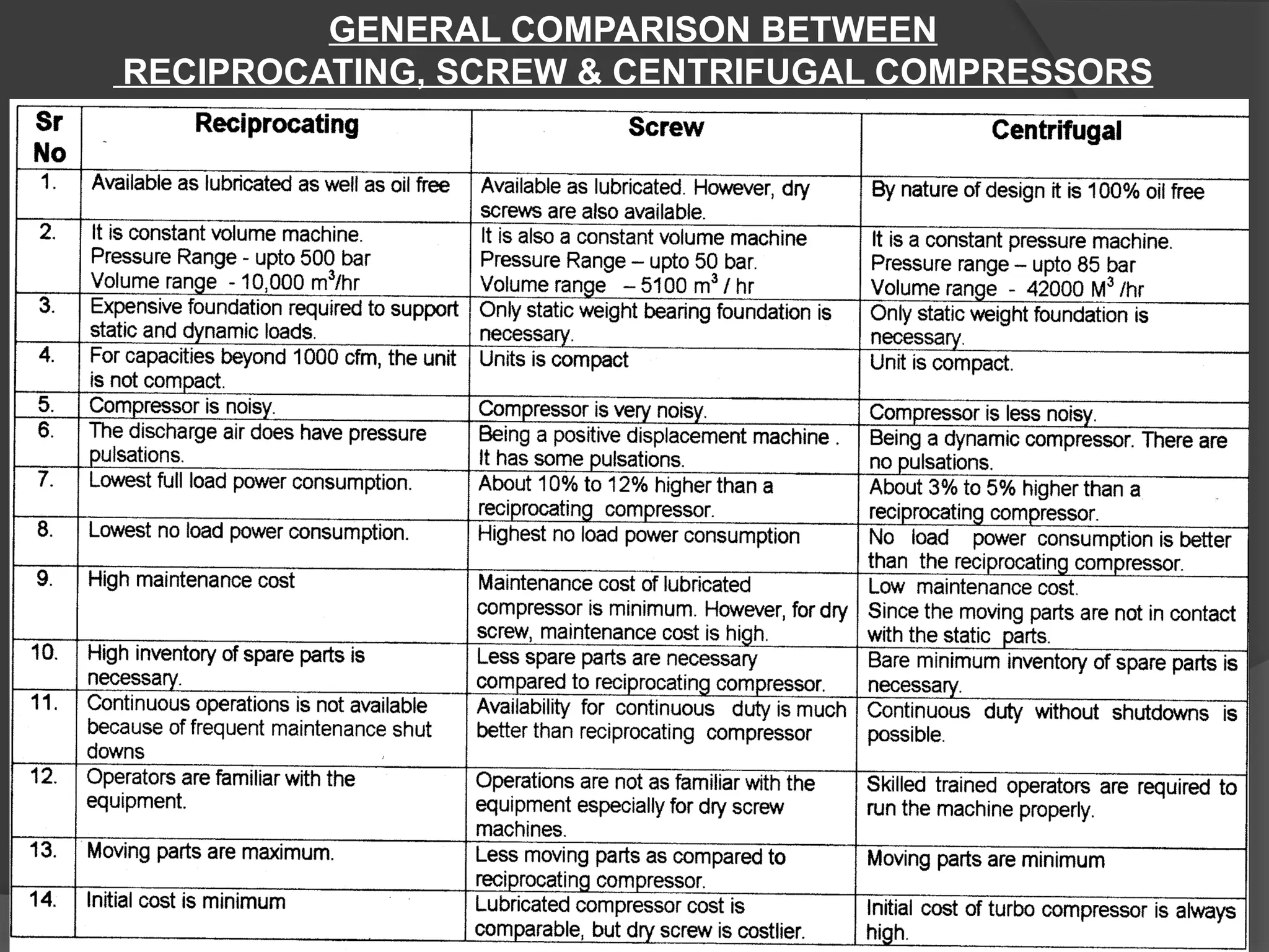
⦿ Comparison Of Compressor
⦿ Energy Saving Of Compressed Air
⦿ Measurement Of System Leakages
⦿ Major Players In Compressor Manufacturing In India
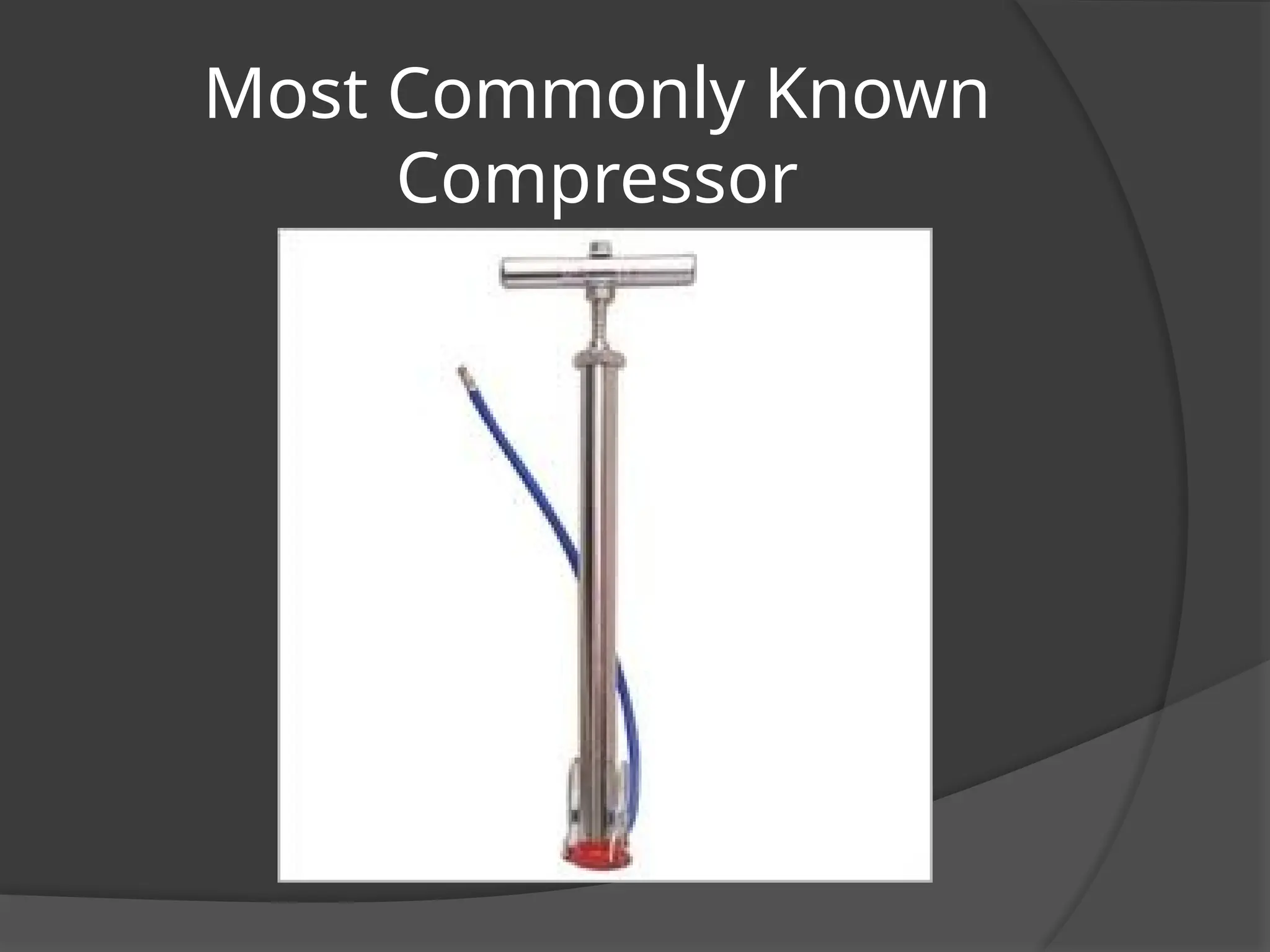
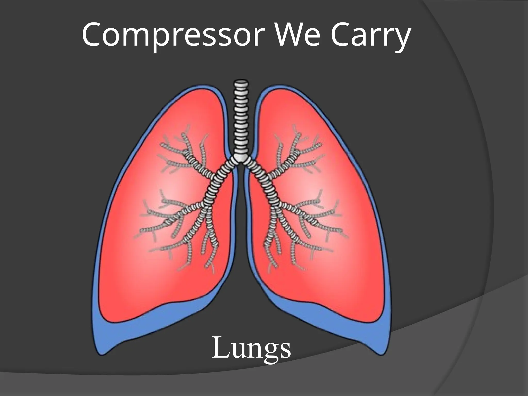
Purposes Of Compressor
⦿Compression of Gas has one basic goal – To deliver gas at a
pressure higher than that originally existing.
⦿ The Original Pressure level may vary from few Kg/cm2
to Hundred
Kg/cm2
.
⦿ The Rise of Pressure may vary from few Kg/cm2
to Hundred
Kg/cm2
.
⦿ Similarly Volume handled from a few cubic feet per minute to
Hundred of Thousands.
Uses
1. To transmit power, as in compressed air system for operating
pneumatic tools.
2. To provide air for combustion.
3. To transport & distribute gas, as in natural gas pipelines & city gas
distribution system.
4. To circulate a gas through a process or a system.
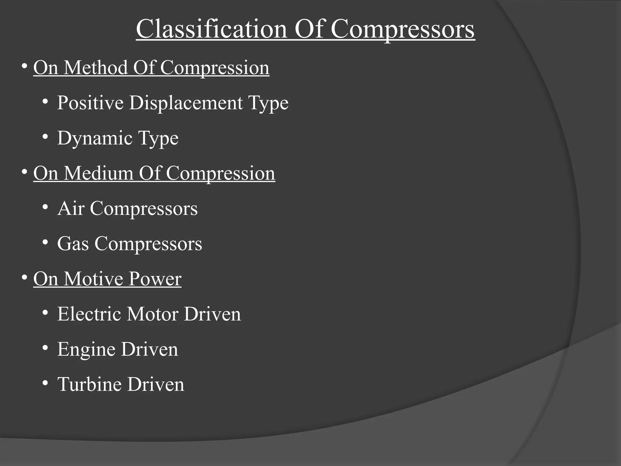
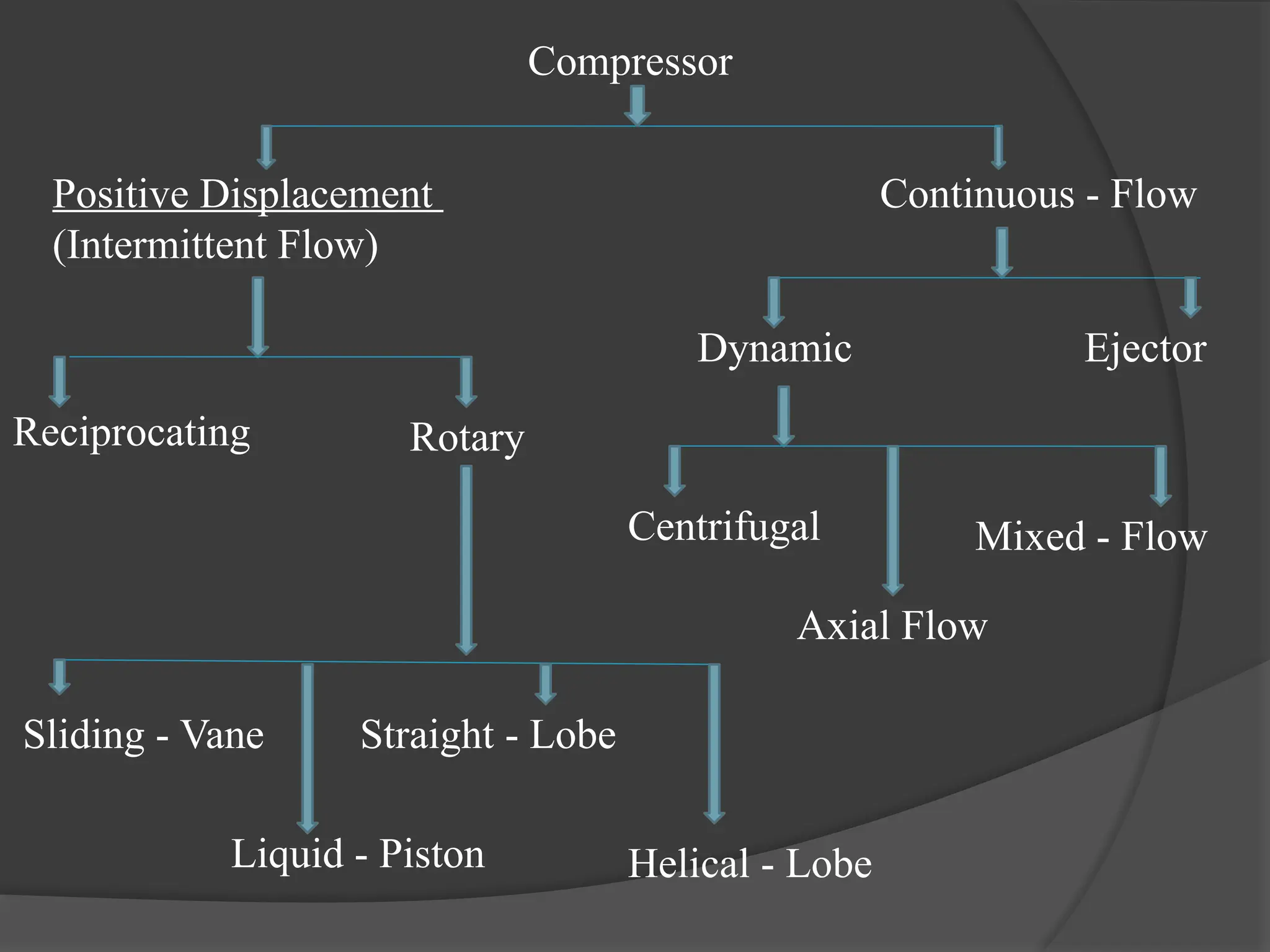
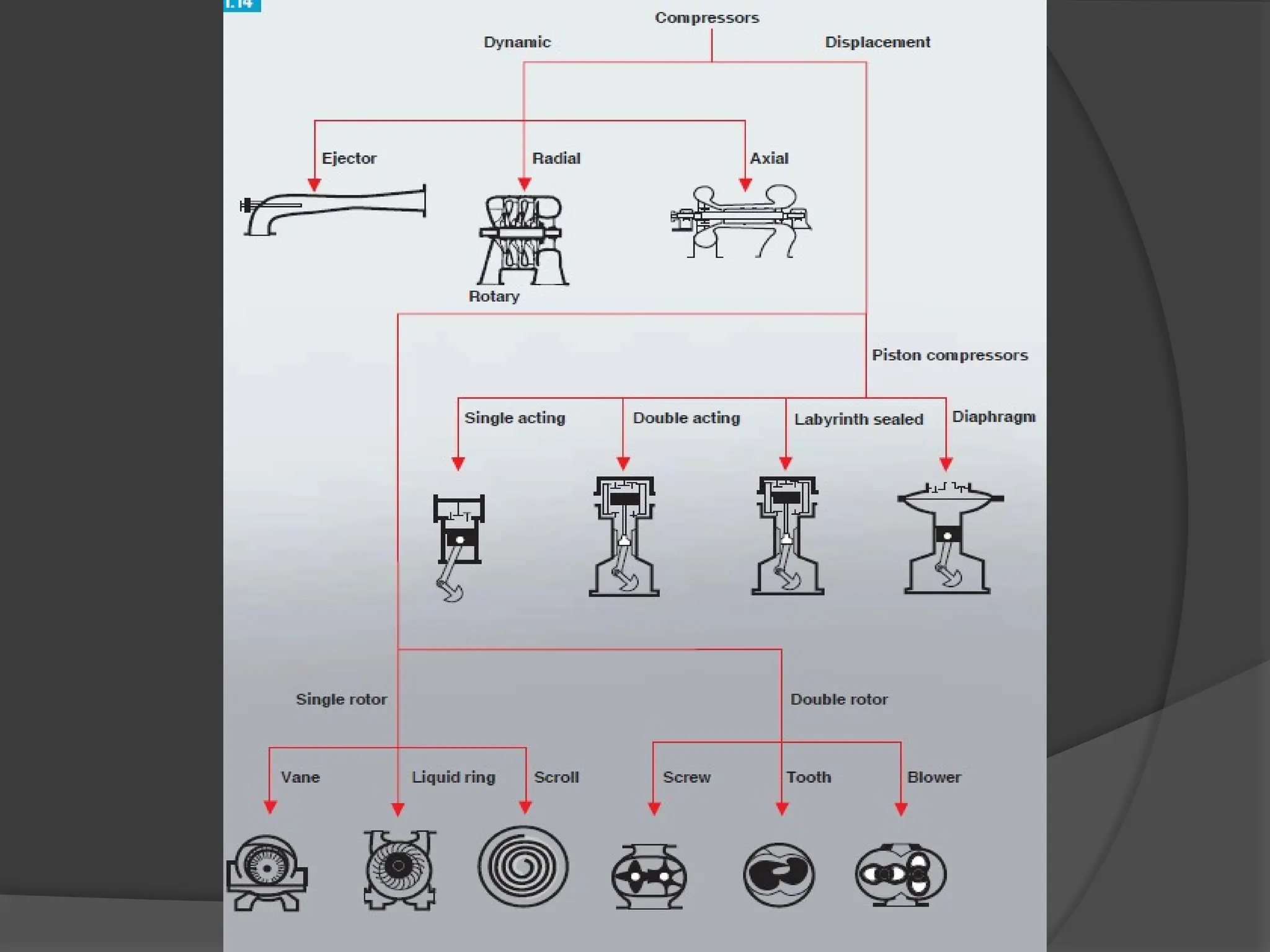
Classification Of Compressors
•On Method Of Compression
• Positive Displacement Type
• Dynamic Type
• On Medium Of Compression
• Air Compressors
• Gas Compressors
• On Motive Power
• Electric Motor Driven
• Engine Driven
• Turbine Driven
8.
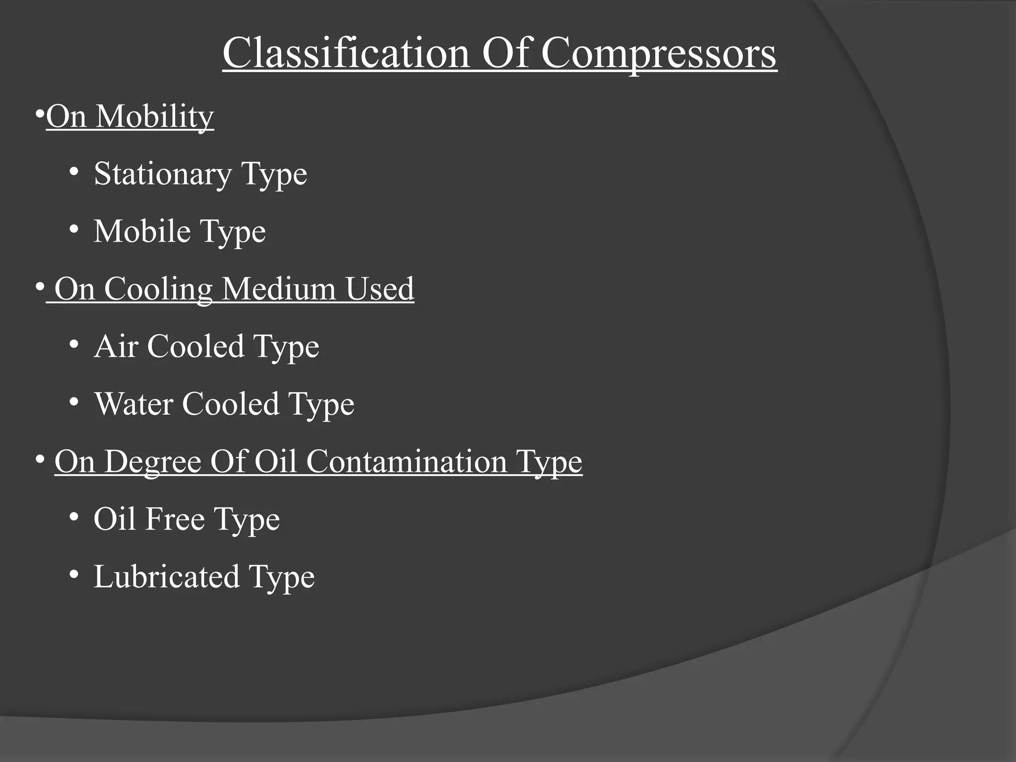
Classification Of Compressors
•OnMobility
• Stationary Type
• Mobile Type
• On Cooling Medium Used
• Air Cooled Type
• Water Cooled Type
• On Degree Of Oil Contamination Type
• Oil Free Type
• Lubricated Type
9.
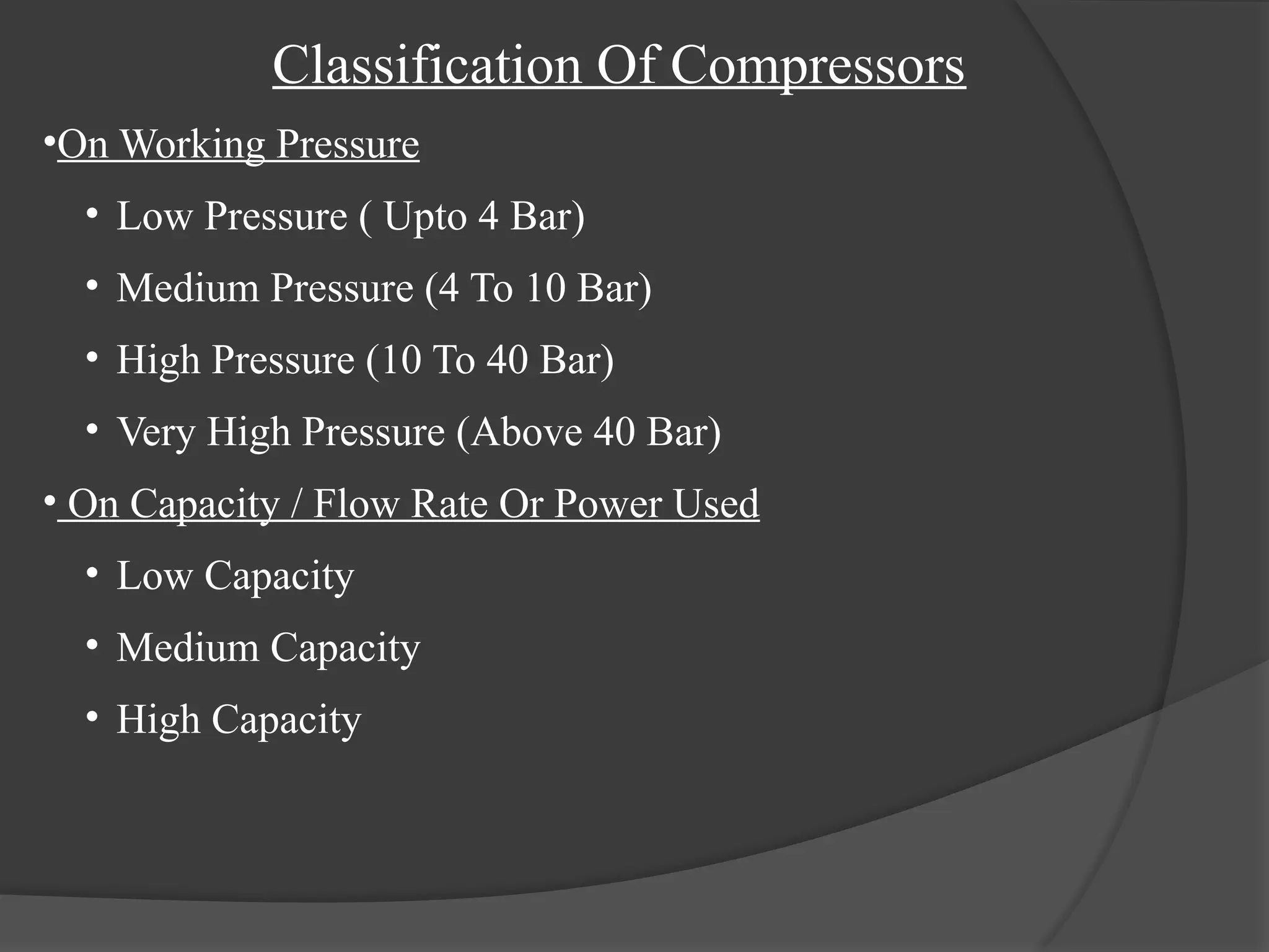
Classification Of Compressors
•OnWorking Pressure
• Low Pressure ( Upto 4 Bar)
• Medium Pressure (4 To 10 Bar)
• High Pressure (10 To 40 Bar)
• Very High Pressure (Above 40 Bar)
• On Capacity / Flow Rate Or Power Used
• Low Capacity
• Medium Capacity
• High Capacity
10.
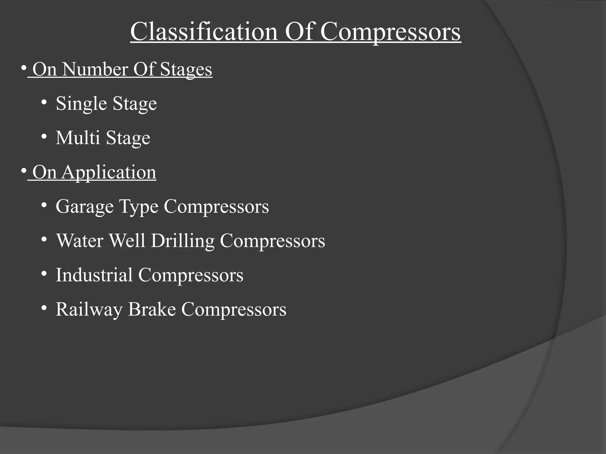
Classification Of Compressors
•On Number Of Stages
• Single Stage
• Multi Stage
• On Application
• Garage Type Compressors
• Water Well Drilling Compressors
• Industrial Compressors
• Railway Brake Compressors
11.
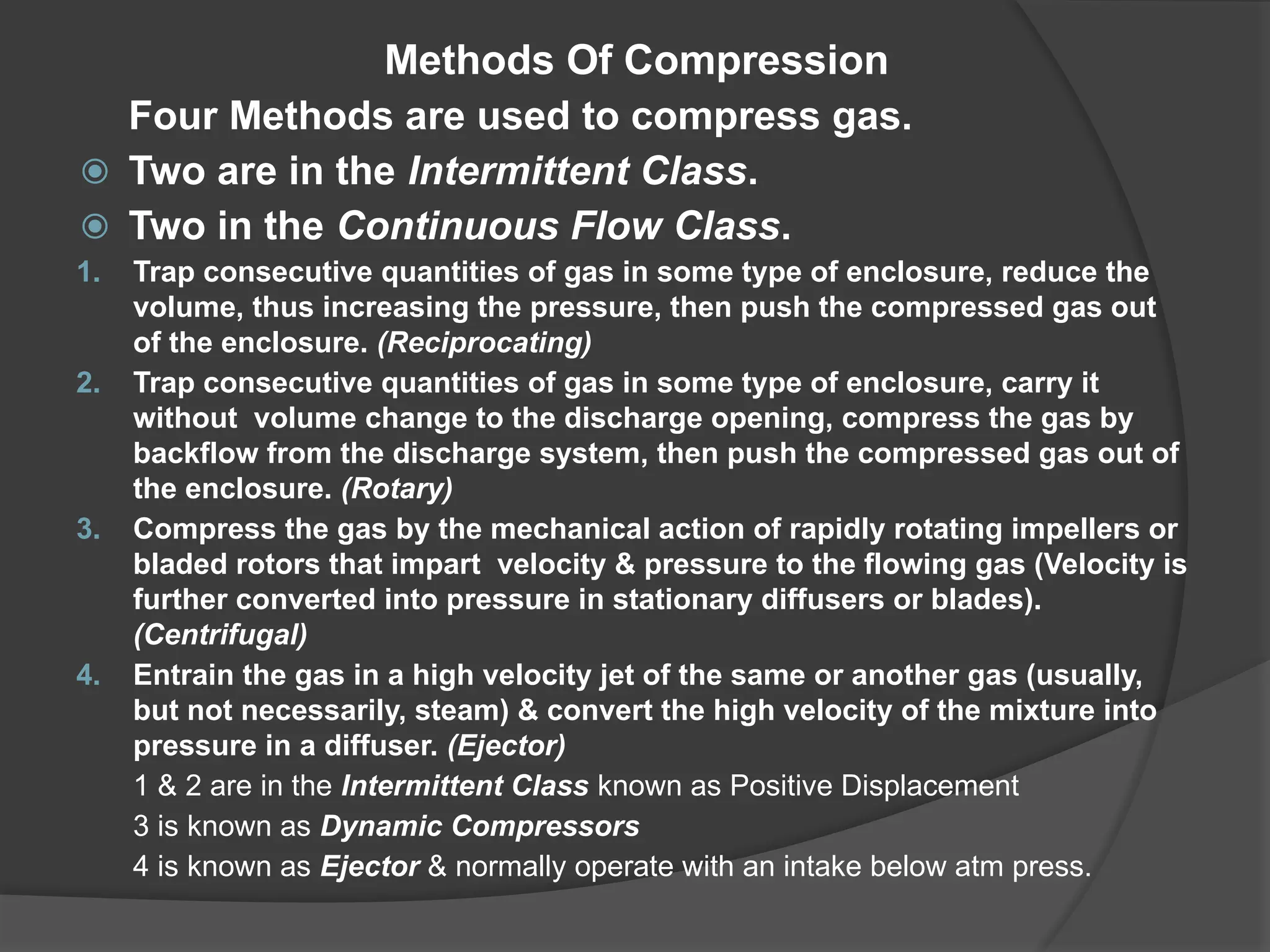
Methods Of Compression
FourMethods are used to compress gas.
⦿ Two are in the Intermittent Class.
⦿ Two in the Continuous Flow Class.
1. Trap consecutive quantities of gas in some type of enclosure, reduce the
volume, thus increasing the pressure, then push the compressed gas out
of the enclosure. (Reciprocating)
2. Trap consecutive quantities of gas in some type of enclosure, carry it
without volume change to the discharge opening, compress the gas by
backflow from the discharge system, then push the compressed gas out of
the enclosure. (Rotary)
3. Compress the gas by the mechanical action of rapidly rotating impellers or
bladed rotors that impart velocity & pressure to the flowing gas (Velocity is
further converted into pressure in stationary diffusers or blades).
(Centrifugal)
4. Entrain the gas in a high velocity jet of the same or another gas (usually,
but not necessarily, steam) & convert the high velocity of the mixture into
pressure in a diffuser. (Ejector)
1 & 2 are in the Intermittent Class known as Positive Displacement
3 is known as Dynamic Compressors
4 is known as Ejector & normally operate with an intake below atm press.
12.
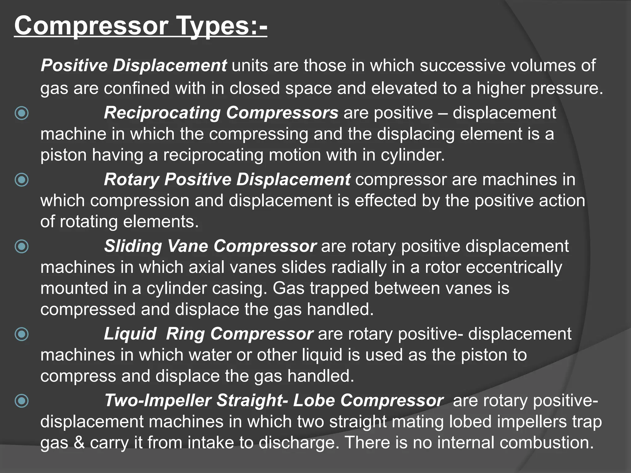
Compressor Types:-
Positive Displacementunits are those in which successive volumes of
gas are confined with in closed space and elevated to a higher pressure.
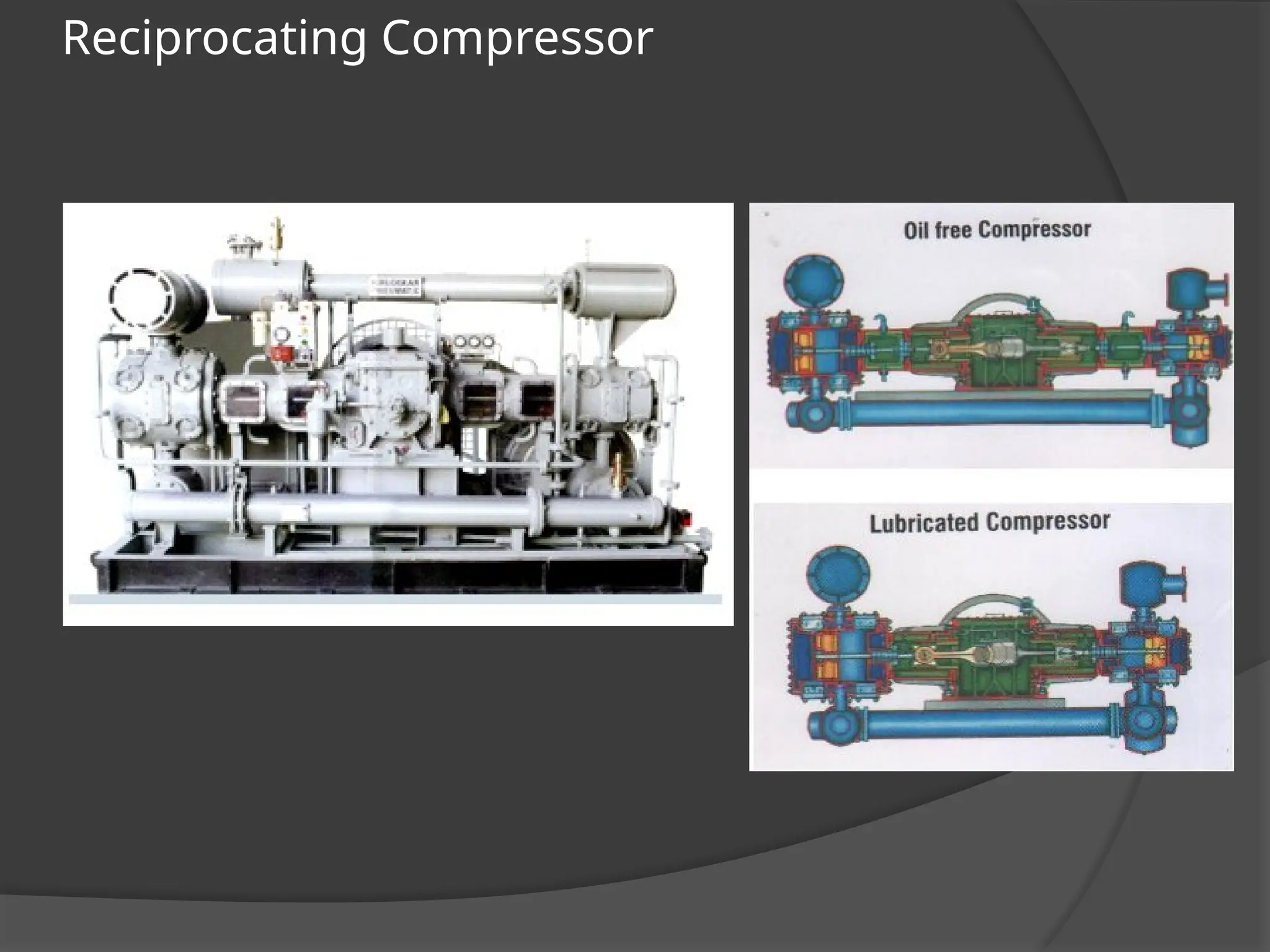
⦿ Reciprocating Compressors are positive – displacement
machine in which the compressing and the displacing element is a
piston having a reciprocating motion with in cylinder.
⦿ Rotary Positive Displacement compressor are machines in
which compression and displacement is effected by the positive action
of rotating elements.
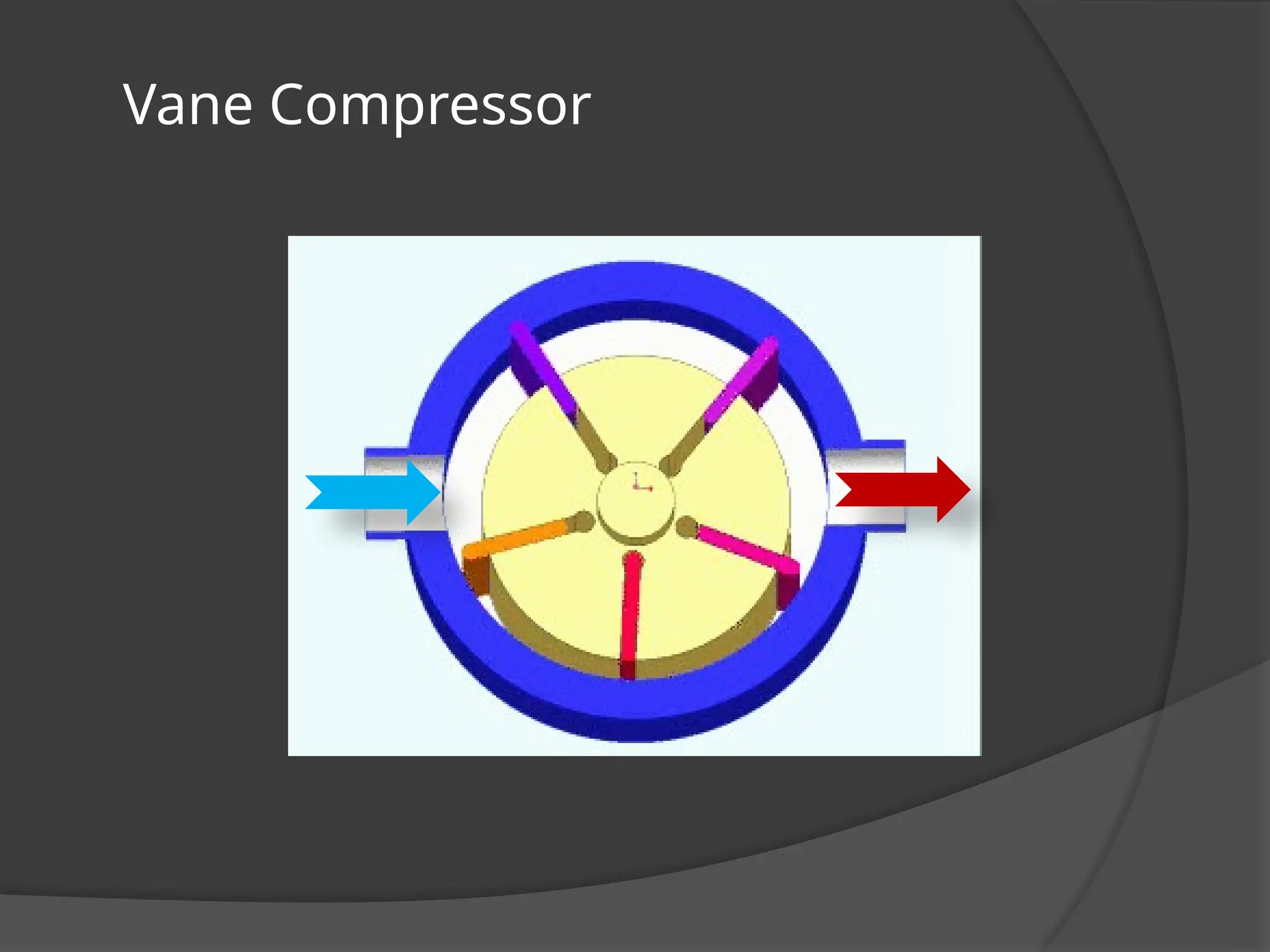
⦿ Sliding Vane Compressor are rotary positive displacement
machines in which axial vanes slides radially in a rotor eccentrically
mounted in a cylinder casing. Gas trapped between vanes is
compressed and displace the gas handled.
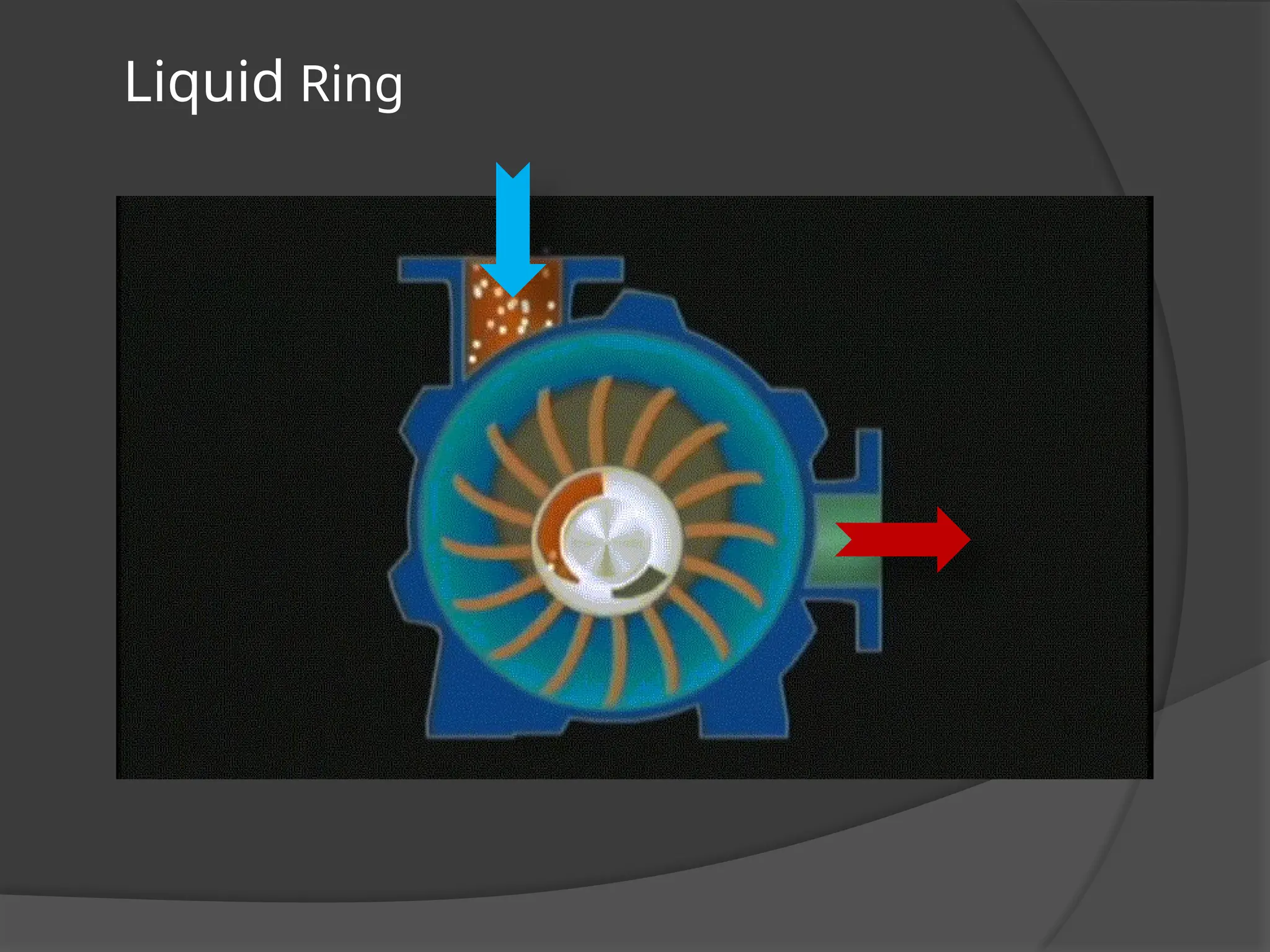
⦿ Liquid Ring Compressor are rotary positive- displacement
machines in which water or other liquid is used as the piston to
compress and displace the gas handled.
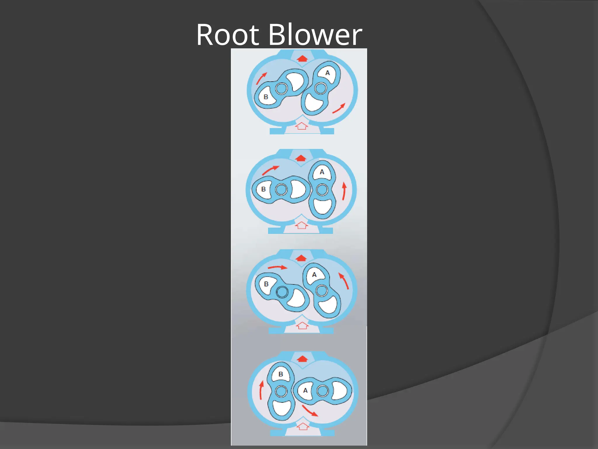
⦿ Two-Impeller Straight- Lobe Compressor are rotary positive-
displacement machines in which two straight mating lobed impellers trap
gas & carry it from intake to discharge. There is no internal combustion.
13.
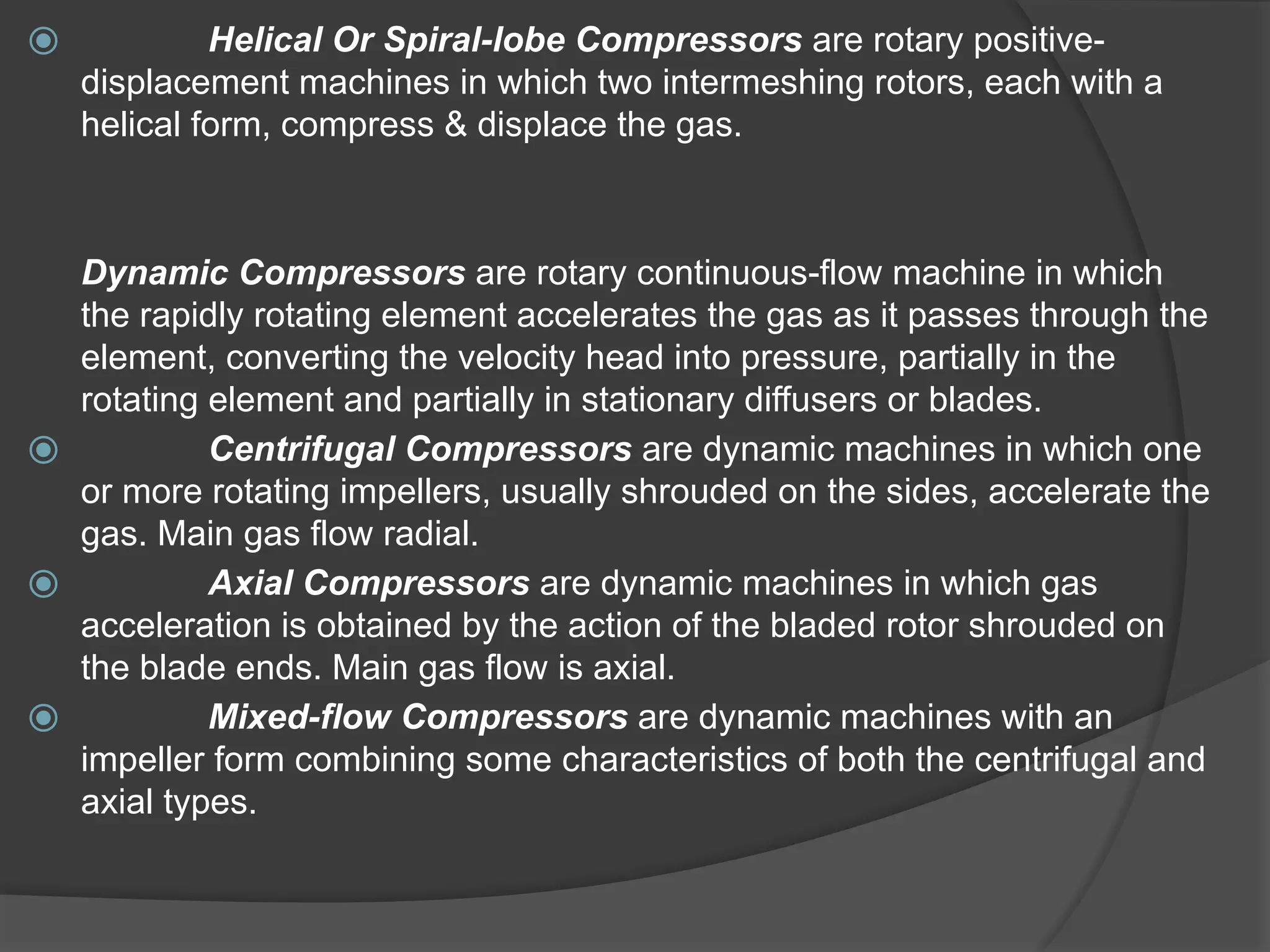
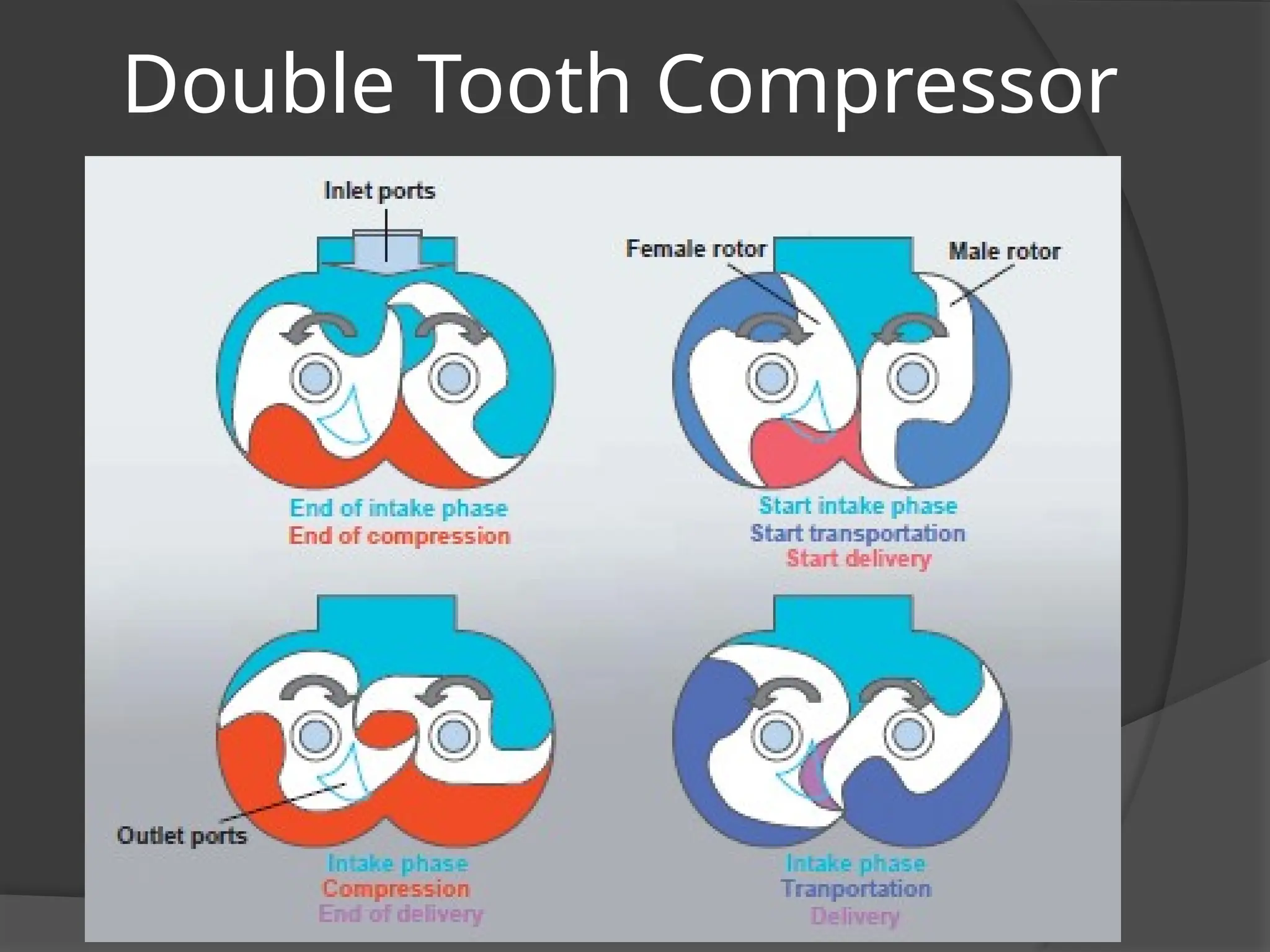
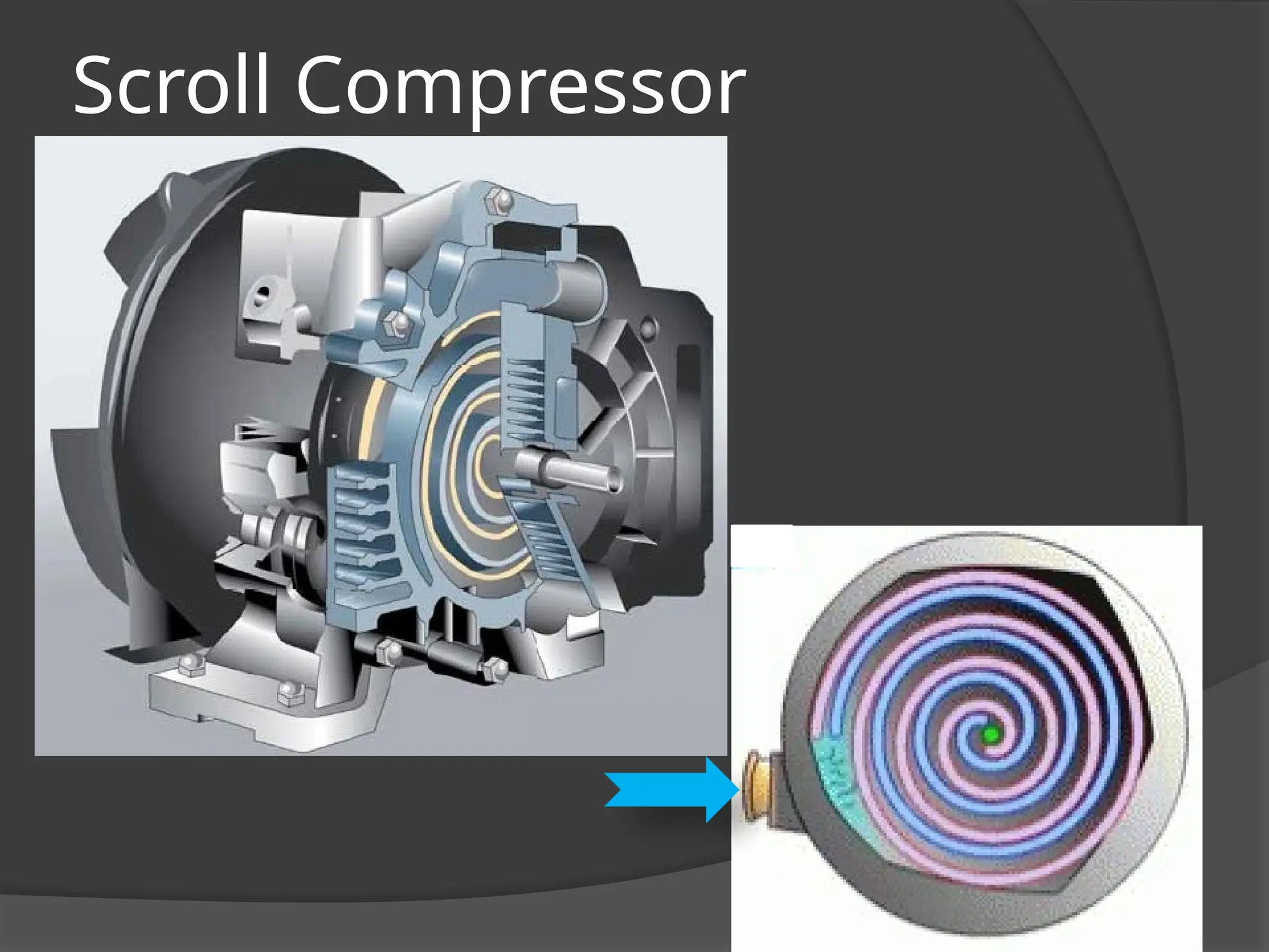
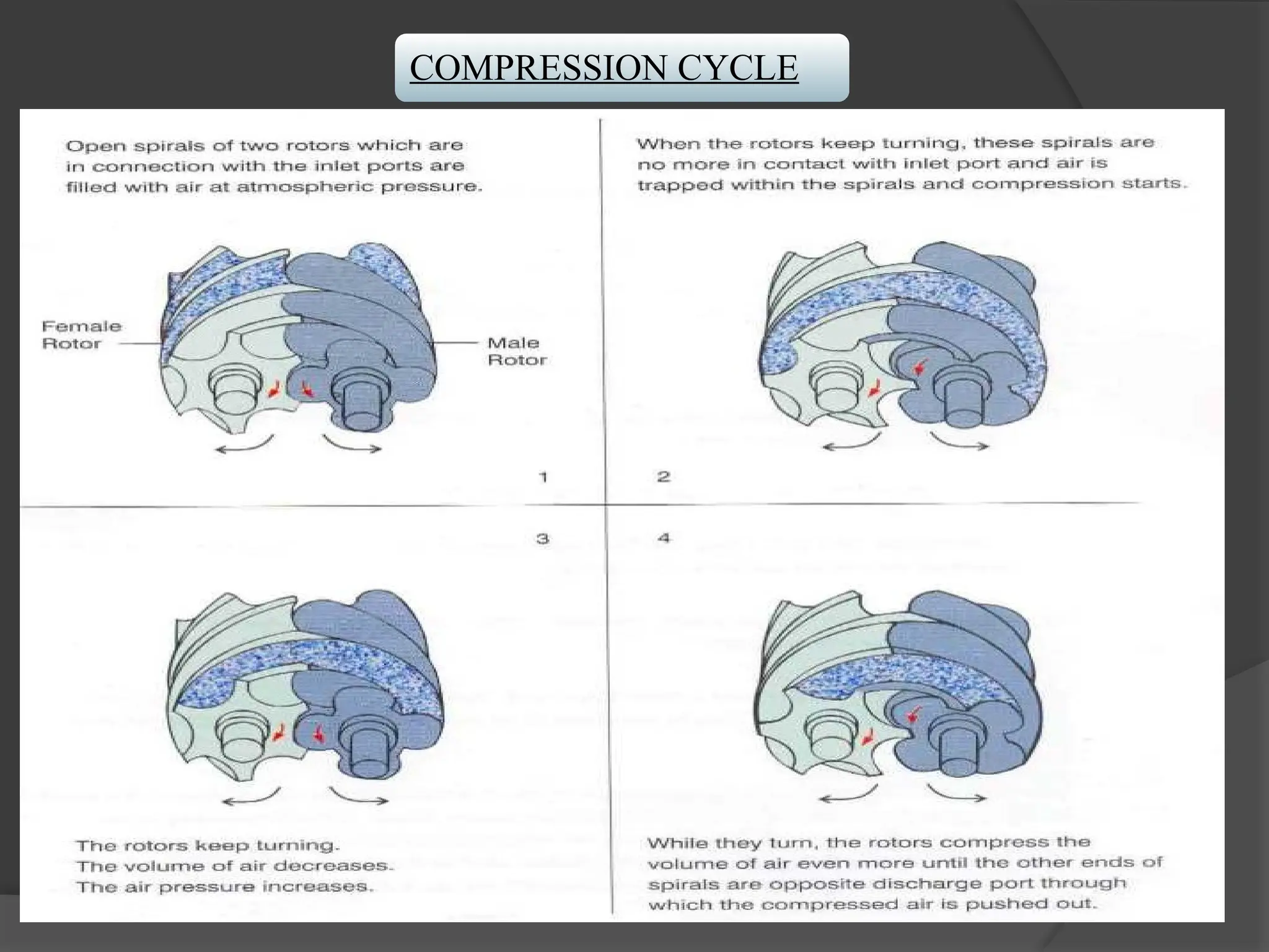
⦿ Helical OrSpiral-lobe Compressors are rotary positive-
displacement machines in which two intermeshing rotors, each with a
helical form, compress & displace the gas.
Dynamic Compressors are rotary continuous-flow machine in which
the rapidly rotating element accelerates the gas as it passes through the
element, converting the velocity head into pressure, partially in the
rotating element and partially in stationary diffusers or blades.
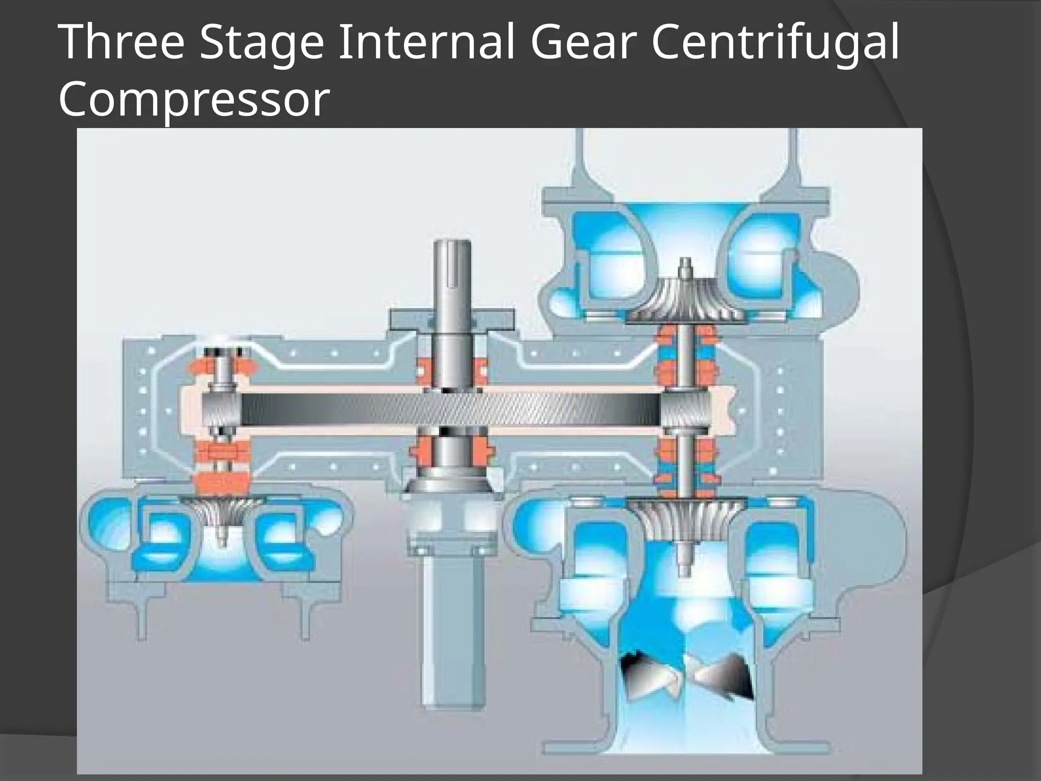
⦿ Centrifugal Compressors are dynamic machines in which one
or more rotating impellers, usually shrouded on the sides, accelerate the
gas. Main gas flow radial.
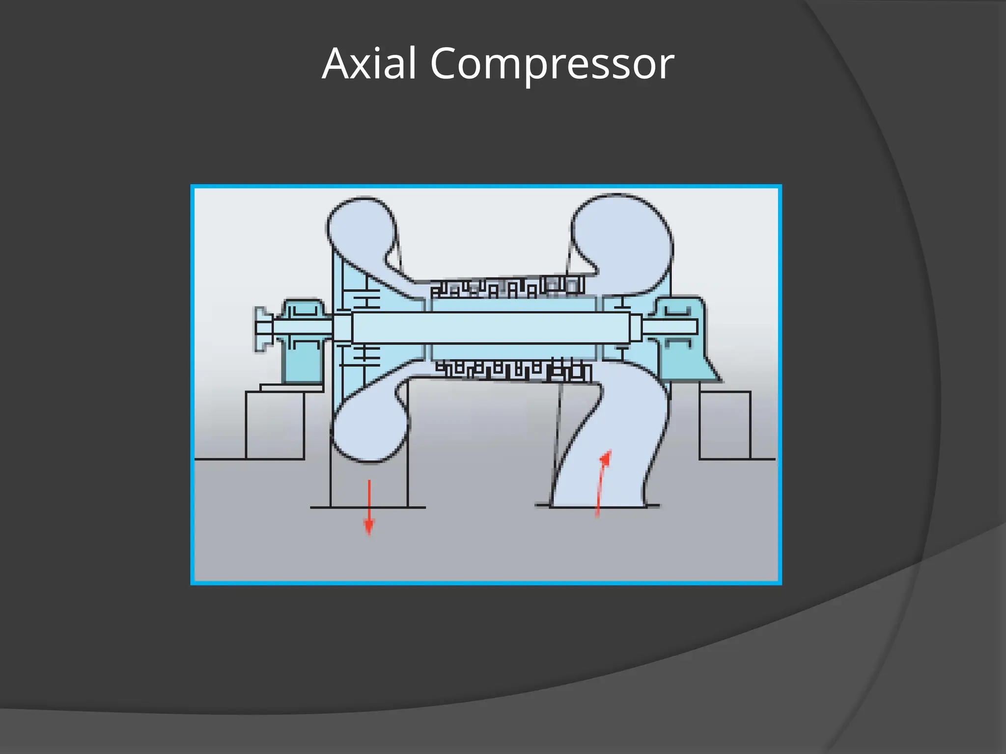
⦿ Axial Compressors are dynamic machines in which gas
acceleration is obtained by the action of the bladed rotor shrouded on
the blade ends. Main gas flow is axial.
⦿ Mixed-flow Compressors are dynamic machines with an
impeller form combining some characteristics of both the centrifugal and
axial types.
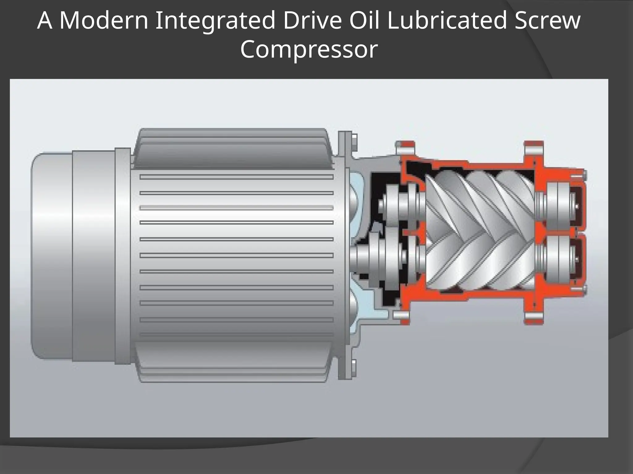
Invention of ScrewCompressors
Svenska Rotor Maskiner
(SRM), Sweden
……Inventor of Screw Compressor
• 90 years in the development of screw
• 400 compressors build as prototype
• 25 licensees world wide
More than….
26.
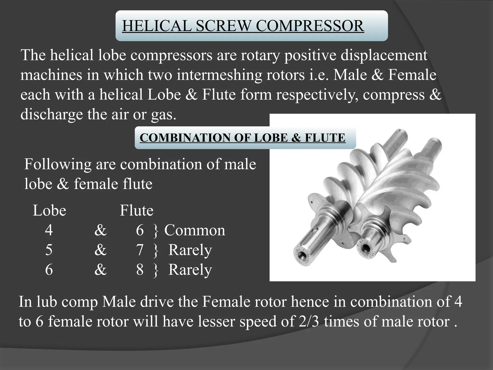
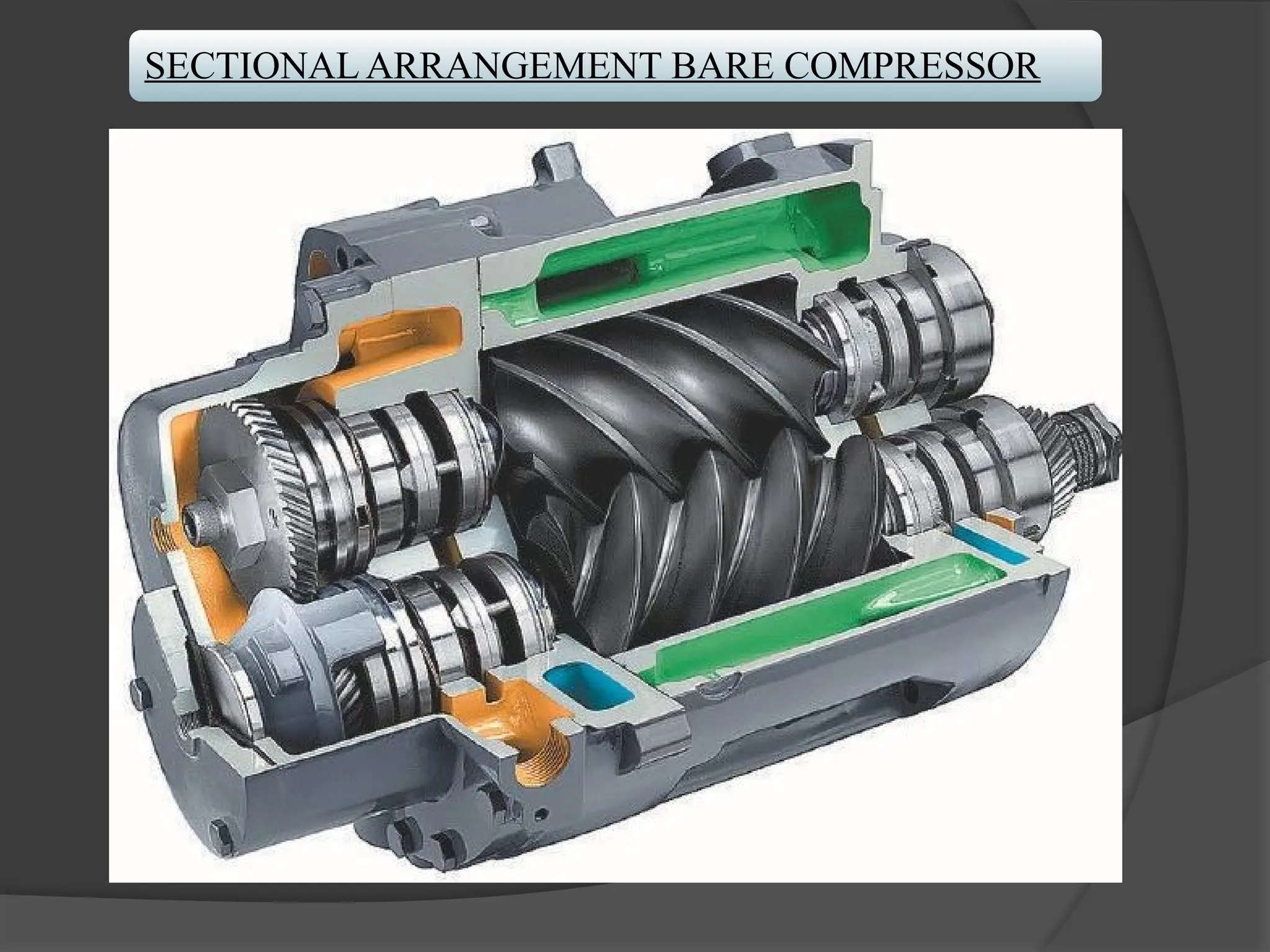
HELICAL SCREW COMPRESSOR
Thehelical lobe compressors are rotary positive displacement
machines in which two intermeshing rotors i.e. Male & Female
each with a helical Lobe & Flute form respectively, compress &
discharge the air or gas.
COMBINATION OF LOBE & FLUTE
Following are combination of male
lobe & female flute
Lobe Flute
4 & 6 } Common
5 & 7 } Rarely
6 & 8 } Rarely
In lub comp Male drive the Female rotor hence in combination of 4
to 6 female rotor will have lesser speed of 2/3 times of male rotor .
27.
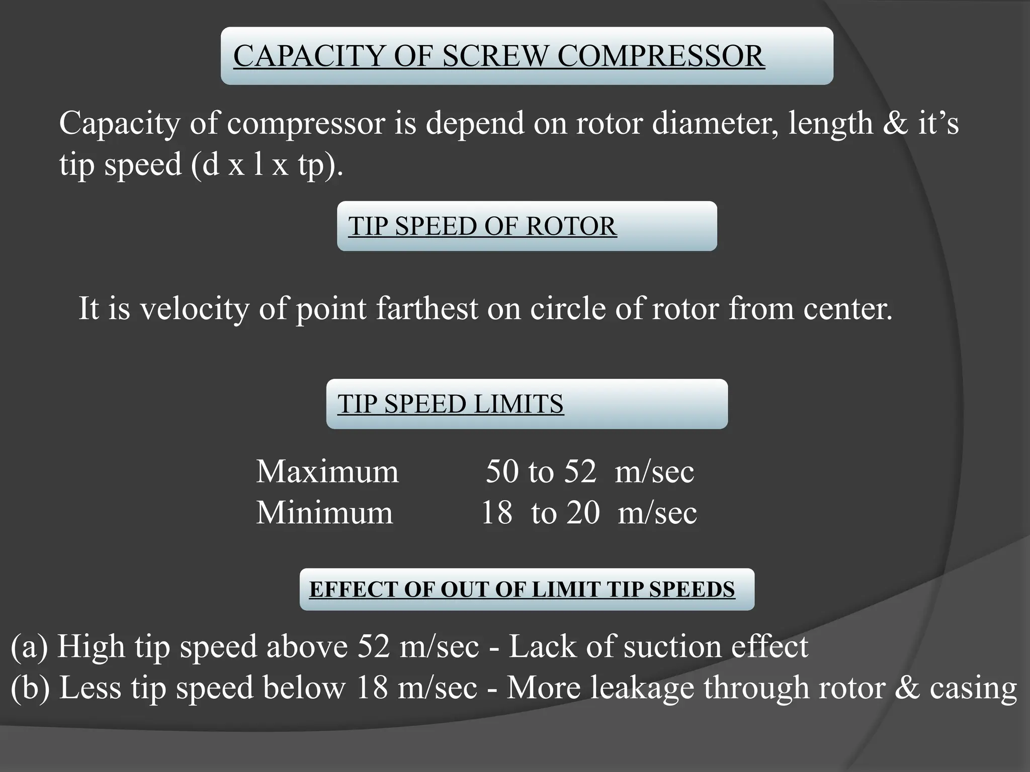
CAPACITY OF SCREWCOMPRESSOR
Capacity of compressor is depend on rotor diameter, length & it’s
tip speed (d x l x tp).
TIP SPEED OF ROTOR
TIP SPEED LIMITS
Maximum 50 to 52 m/sec
Minimum 18 to 20 m/sec
EFFECT OF OUT OF LIMIT TIP SPEEDS
(a) High tip speed above 52 m/sec - Lack of suction effect
(b) Less tip speed below 18 m/sec - More leakage through rotor & casing
It is velocity of point farthest on circle of rotor from center.
28.
ROTOR DIAMETER TOLENGTH RATIO
l/d ratio of length to diameter of rotor should be between
1. 6 to 1. 8.
Excess ratio more than 2 i.e length of rotor will cause
deflection of rotor resulting in scoring of rotor casing.
o Screw to Screw Gap- 3 to 4 micron
o Screw to Casing Gap- 3 to 4 micron
29.
WRAP ANGLE
This isan angle provided on rotors for lobe & flute for mating
suction & delivery port in suction & delivery casing respectively
General wrap angle is 300 degree
Maximum recommended is 330 degree
360 degree wrap angle will simultaneously connect suction &
delivery port through rotor causing blow back hence same is not
permitted.
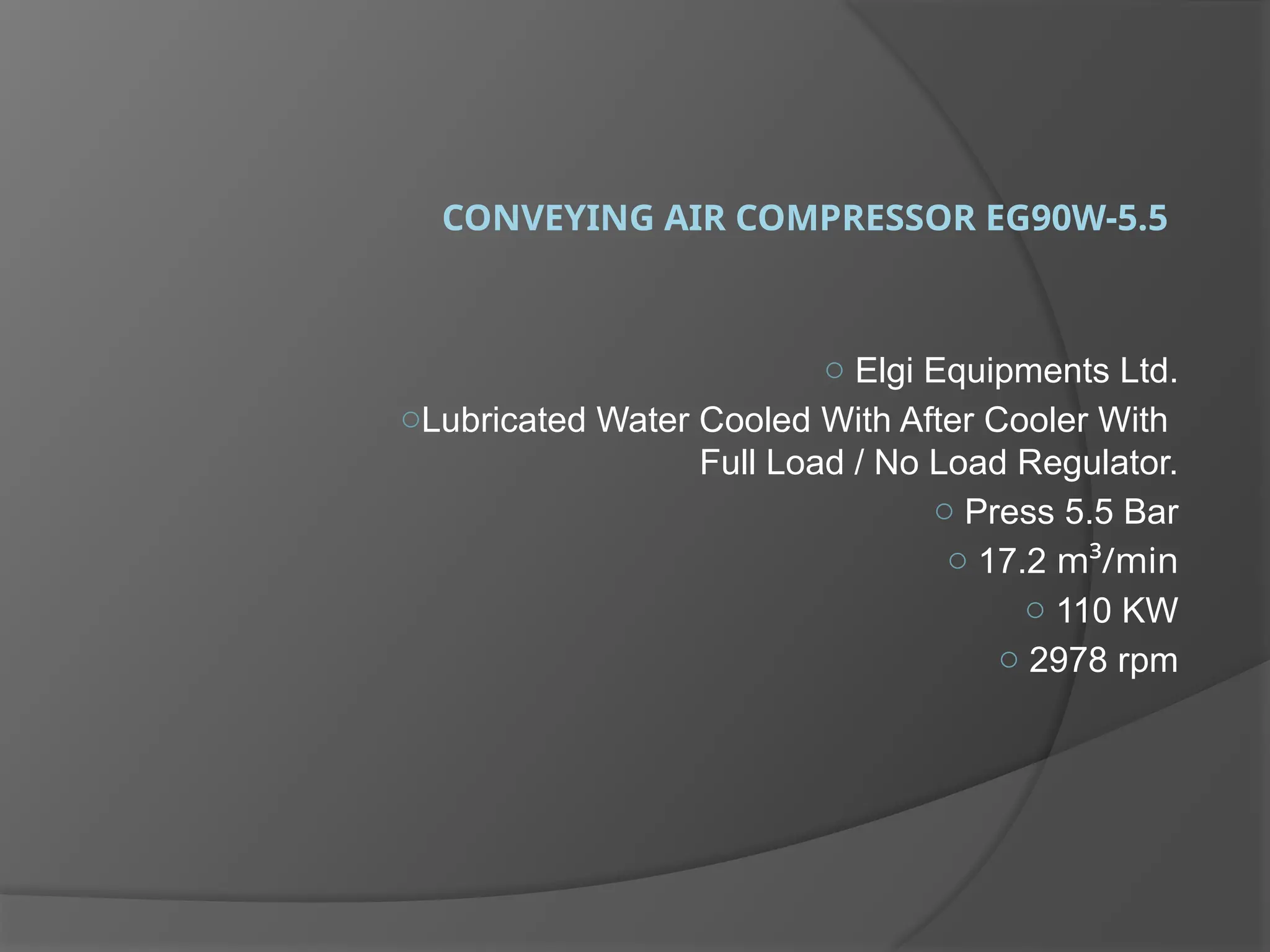
CONVEYING AIR COMPRESSOREG90W-5.5
o Elgi Equipments Ltd.
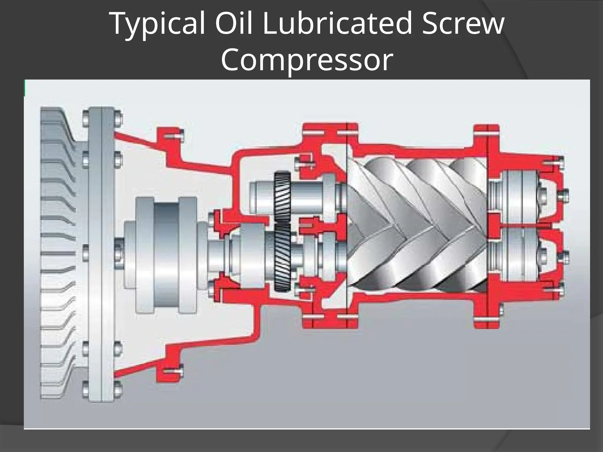
oLubricated Water Cooled With After Cooler With
Full Load / No Load Regulator.
o Press 5.5 Bar
o 17.2 m³/min
o 110 KW
o 2978 rpm
35.
Operating Parameter
Load Pressure4.5 Bar
UnLoad Pressure 5.5 Bar
Air Outlet /Element Temp Fan 85°C
Warning 105°C
Shut Down 110°C
Δ Delay 10 sec
Inlet Pressure 1.8 to 2kg/cm2
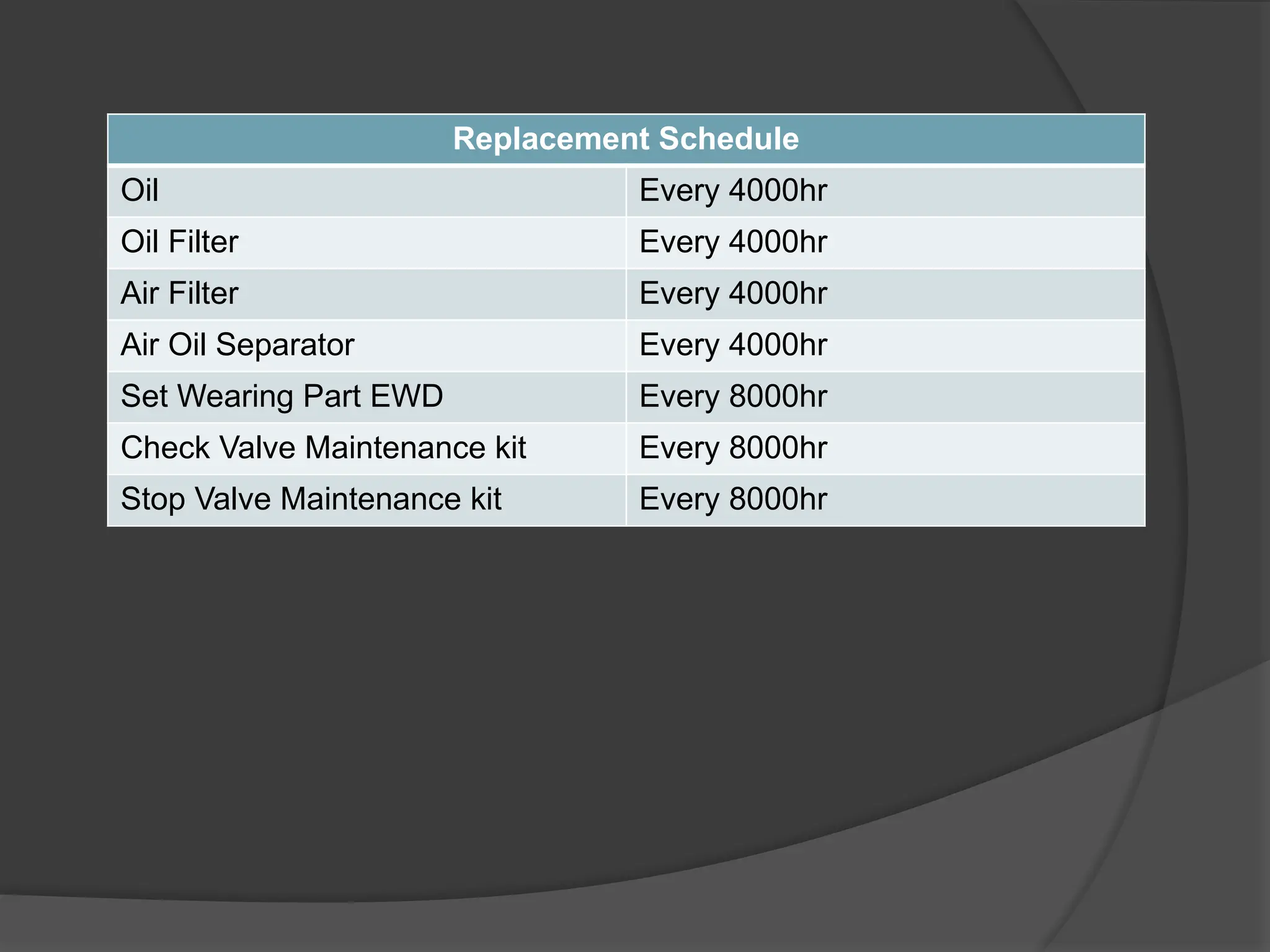
Replacement Schedule
Oil Every4000hr
Oil Filter Every 4000hr
Air Filter Every 4000hr
Air Oil Separator Every 4000hr
Set Wearing Part EWD Every 8000hr
Check Valve Maintenance kit Every 8000hr
Stop Valve Maintenance kit Every 8000hr
38.
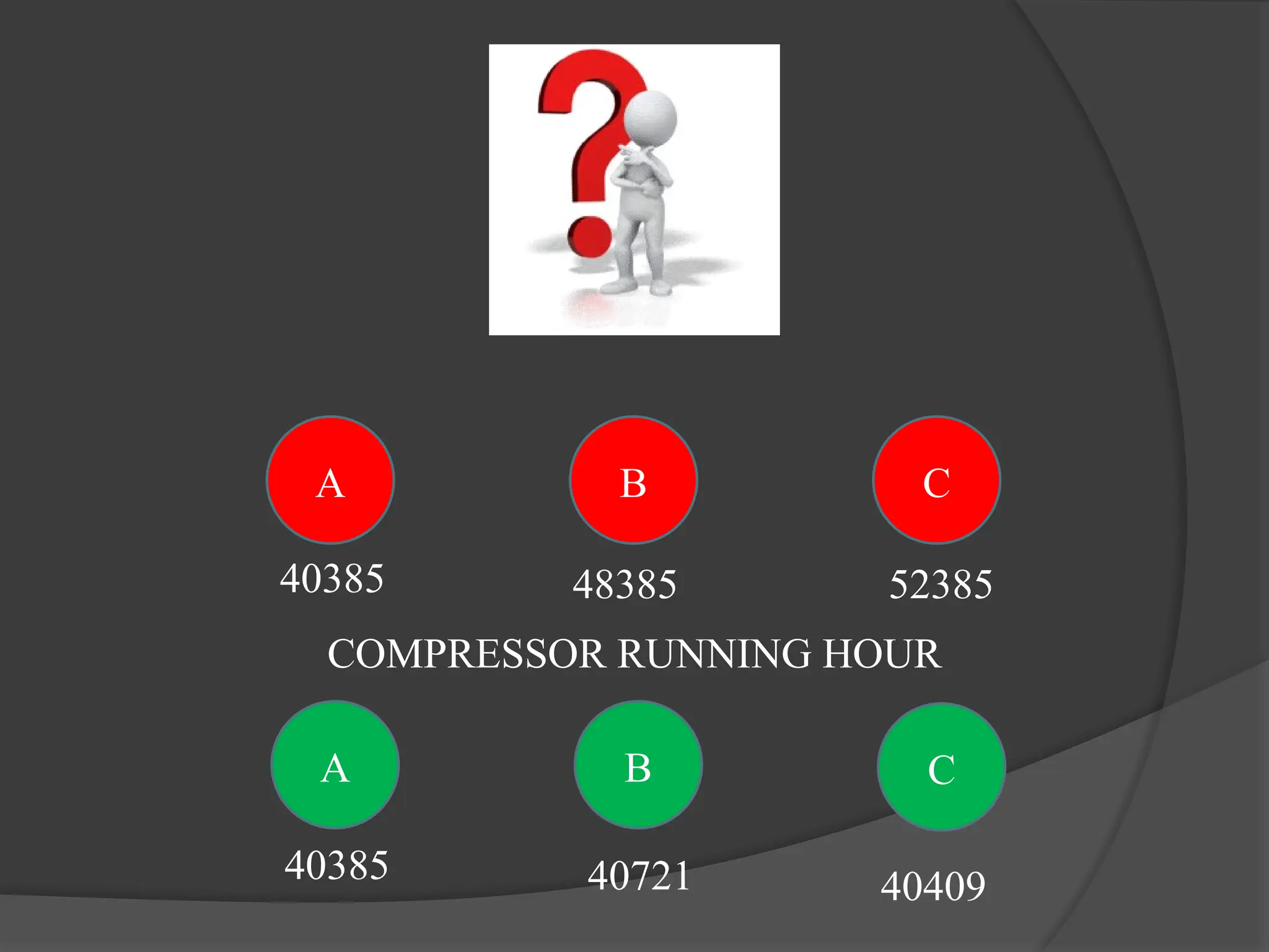
A C
B
A C
B
4038540409
40721
40385 48385 52385
COMPRESSOR RUNNING HOUR
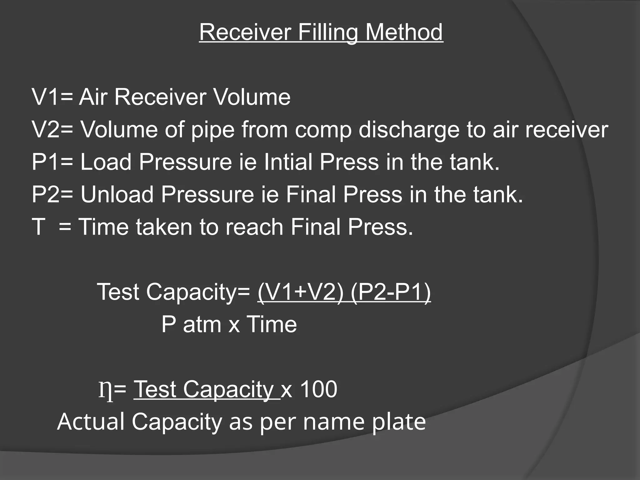
Receiver Filling Method
V1=Air Receiver Volume
V2= Volume of pipe from comp discharge to air receiver
P1= Load Pressure ie Intial Press in the tank.
P2= Unload Pressure ie Final Press in the tank.
T = Time taken to reach Final Press.
Test Capacity= (V1+V2) (P2-P1)
P atm x Time
Ƞ= Test Capacity x 100
Actual Capacity as per name plate
41.
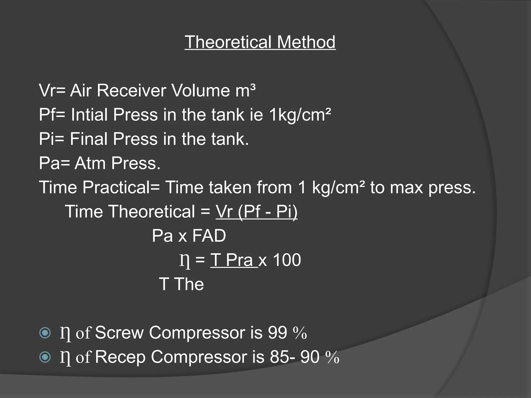
Theoretical Method
Vr= AirReceiver Volume m³
Pf= Intial Press in the tank ie 1kg/cm²
Pi= Final Press in the tank.
Pa= Atm Press.
Time Practical= Time taken from 1 kg/cm² to max press.
Time Theoretical = Vr (Pf - Pi)
Pa x FAD
Ƞ = T Pra x 100
T The
⦿ of
Ƞ Screw Compressor is 99 %
⦿ of
Ƞ Recep Compressor is 85- 90 %
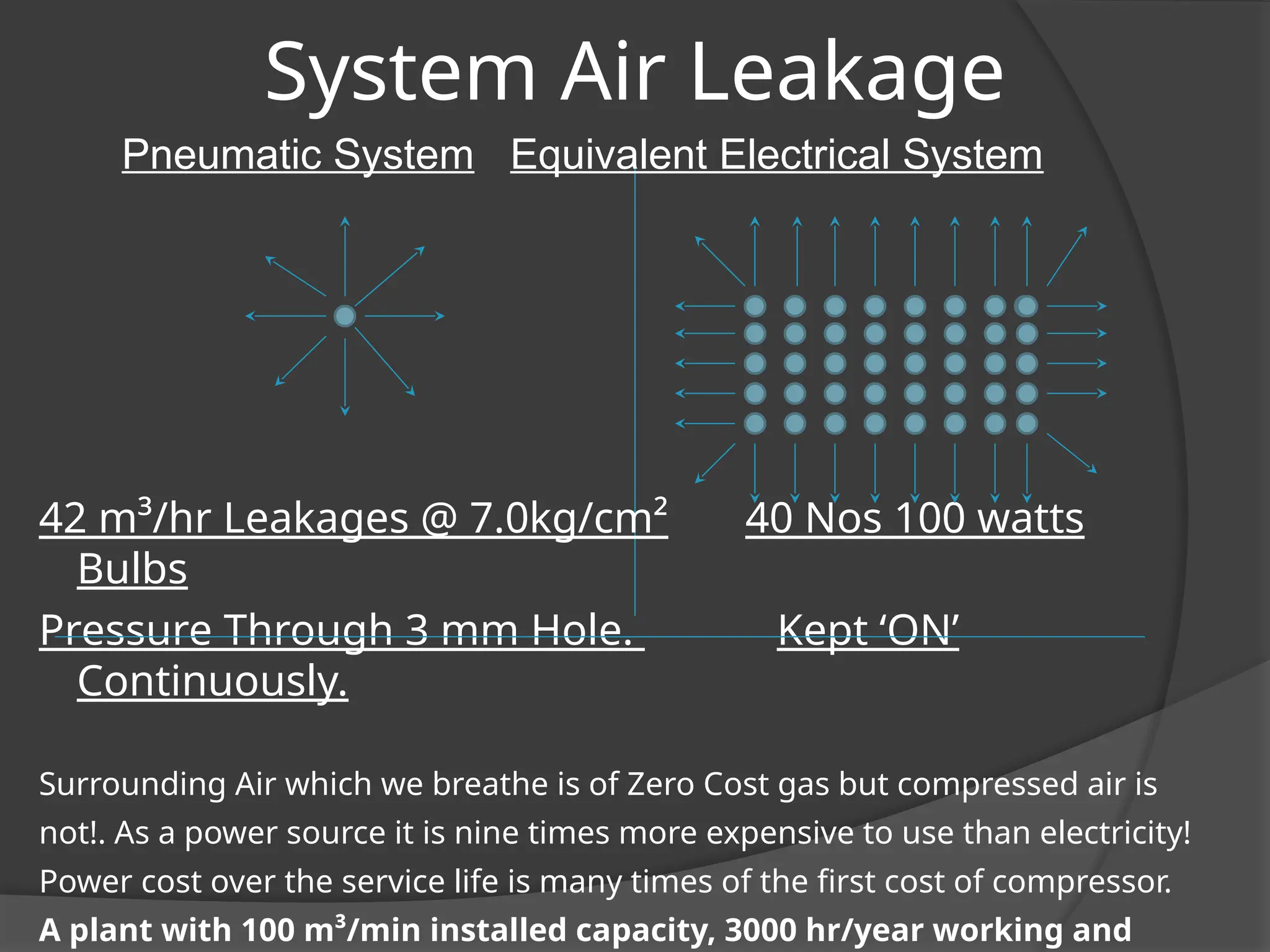
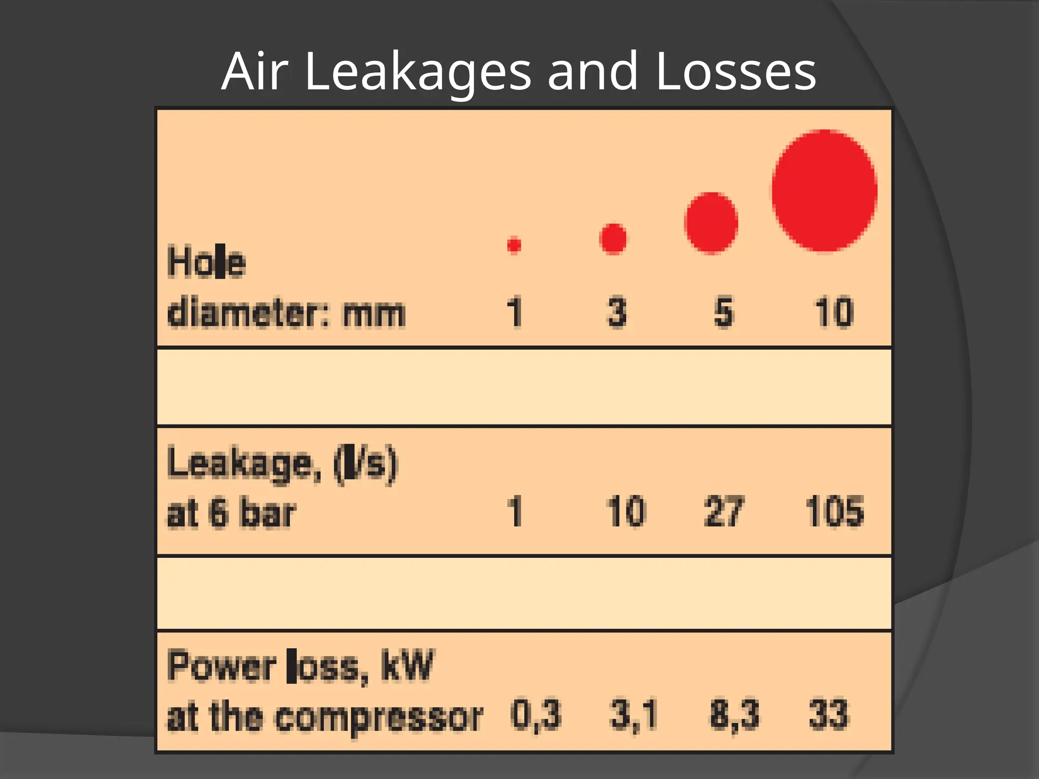
System Air Leakage
PneumaticSystem Equivalent Electrical System
42 m³/hr Leakages @ 7.0kg/cm² 40 Nos 100 watts
Bulbs
Pressure Through 3 mm Hole. Kept ‘ON’
Continuously.
Surrounding Air which we breathe is of Zero Cost gas but compressed air is
not!. As a power source it is nine times more expensive to use than electricity!
Power cost over the service life is many times of the first cost of compressor.
A plant with 100 m³/min installed capacity, 3000 hr/year working and
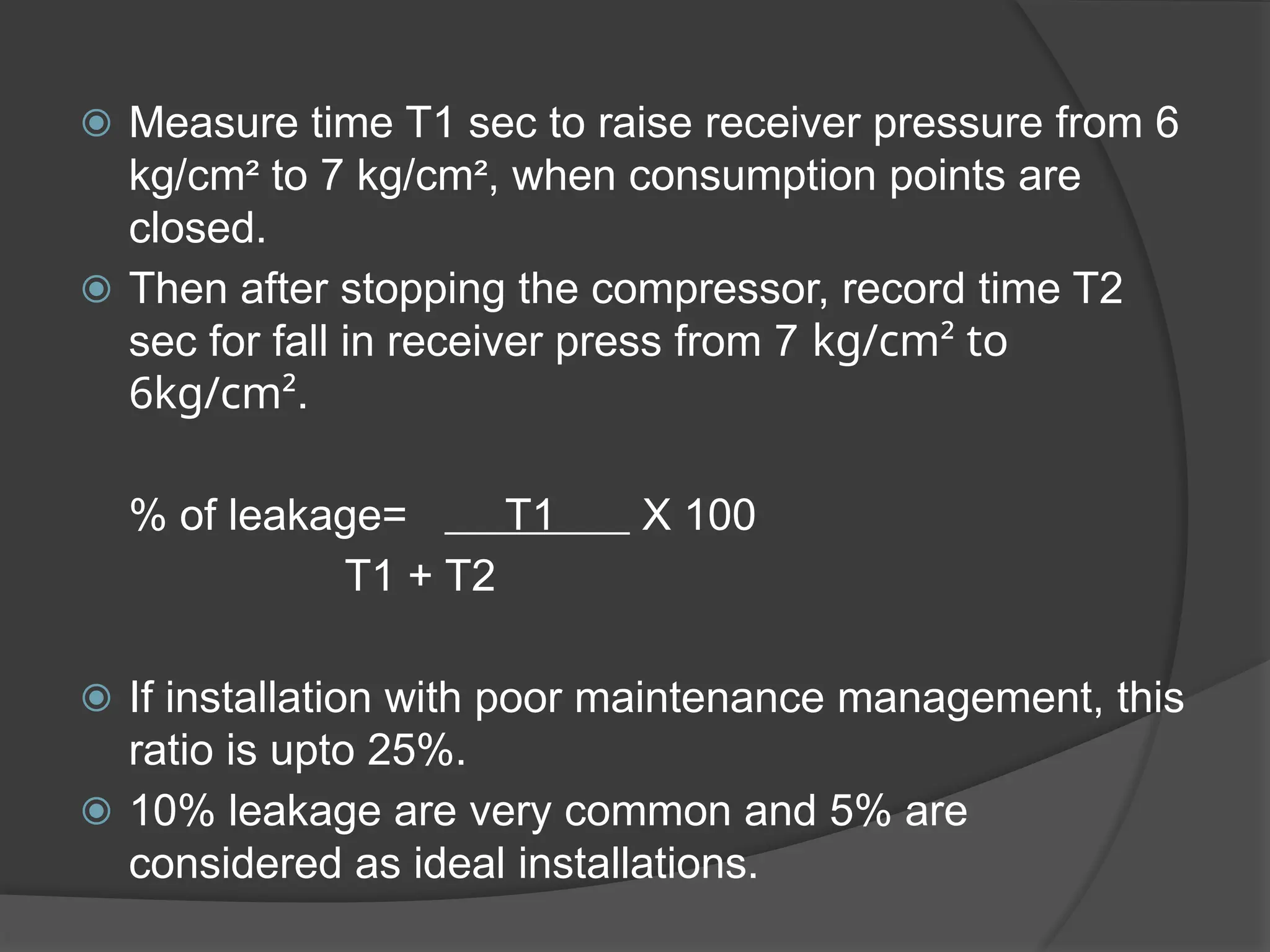
⦿ Measure timeT1 sec to raise receiver pressure from 6
kg/cm² to 7 kg/cm², when consumption points are
closed.
⦿ Then after stopping the compressor, record time T2
sec for fall in receiver press from 7 kg/cm² to
6kg/cm².
% of leakage= T1 X 100
T1 + T2
⦿ If installation with poor maintenance management, this
ratio is upto 25%.
⦿ 10% leakage are very common and 5% are
considered as ideal installations.
52.
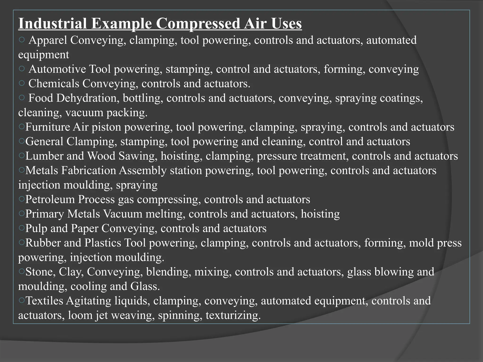
Industrial Example CompressedAir Uses
o Apparel Conveying, clamping, tool powering, controls and actuators, automated
equipment
o Automotive Tool powering, stamping, control and actuators, forming, conveying
o Chemicals Conveying, controls and actuators.
o Food Dehydration, bottling, controls and actuators, conveying, spraying coatings,
cleaning, vacuum packing.
oFurniture Air piston powering, tool powering, clamping, spraying, controls and actuators
oGeneral Clamping, stamping, tool powering and cleaning, control and actuators
oLumber and Wood Sawing, hoisting, clamping, pressure treatment, controls and actuators
oMetals Fabrication Assembly station powering, tool powering, controls and actuators
injection moulding, spraying
oPetroleum Process gas compressing, controls and actuators
oPrimary Metals Vacuum melting, controls and actuators, hoisting
oPulp and Paper Conveying, controls and actuators
oRubber and Plastics Tool powering, clamping, controls and actuators, forming, mold press
powering, injection moulding.
oStone, Clay, Conveying, blending, mixing, controls and actuators, glass blowing and
moulding, cooling and Glass.
oTextiles Agitating liquids, clamping, conveying, automated equipment, controls and
actuators, loom jet weaving, spinning, texturizing.
53.
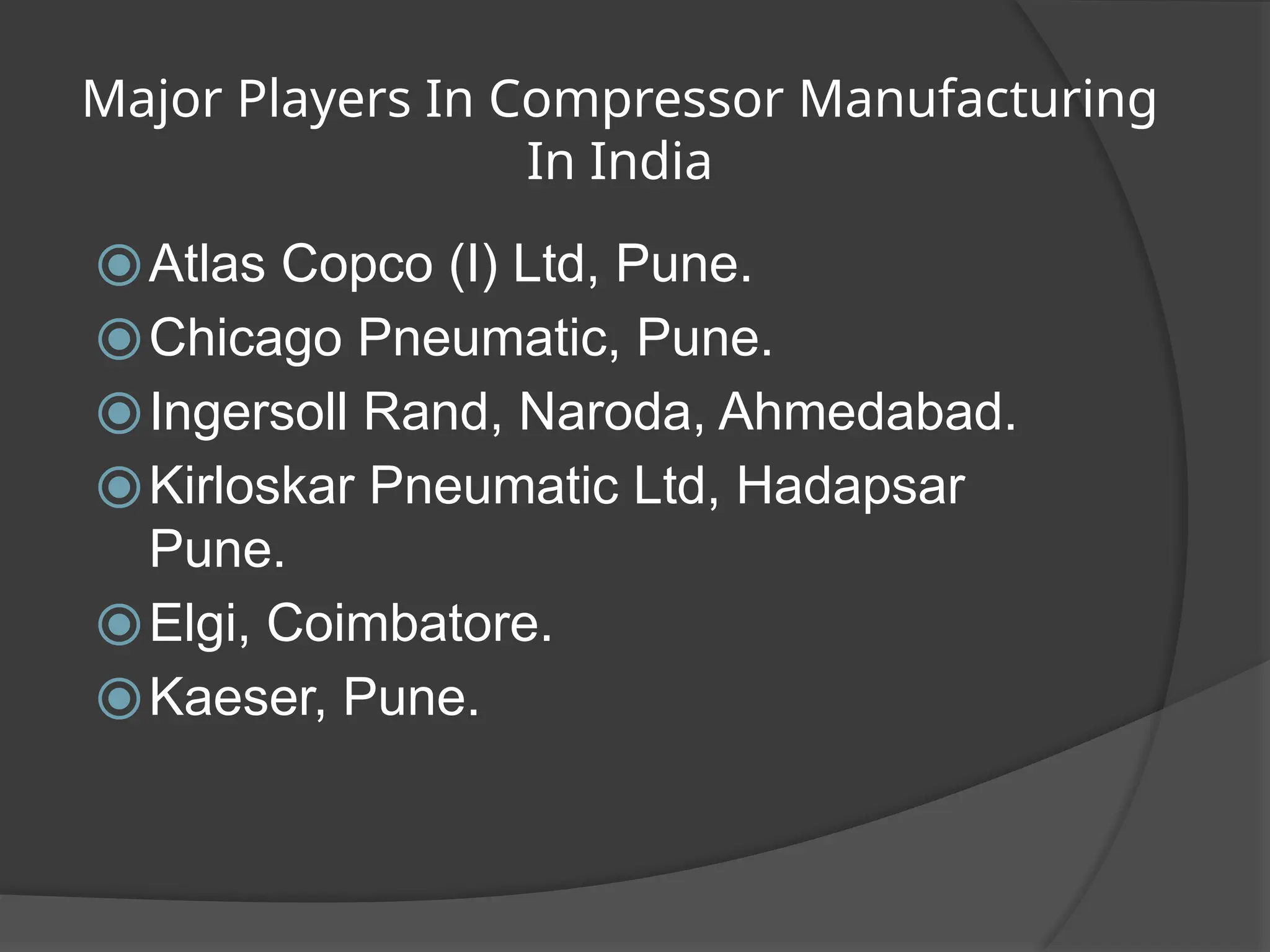
Major Players InCompressor Manufacturing
In India
⦿Atlas Copco (I) Ltd, Pune.
⦿Chicago Pneumatic, Pune.
⦿Ingersoll Rand, Naroda, Ahmedabad.
⦿Kirloskar Pneumatic Ltd, Hadapsar
Pune.
⦿Elgi, Coimbatore.
⦿Kaeser, Pune.


![SBP- Air compressor [Compatibility Mode].pdf](https://cdn.slidesharecdn.com/ss_thumbnails/sbp-aircompressorcompatibilitymode-241227102120-b6a67cde-thumbnail.jpg?width=640&height=640&fit=bounds)


