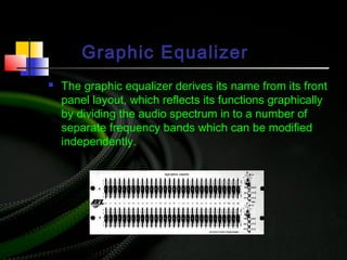
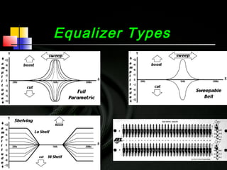
The document provides an overview of equalizers and their types, explaining how they function as frequency selective amplifiers that can boost or cut specific audio frequencies. It details the characteristics of parametric, bell curve, shelving, and graphic equalizers, along with the importance of bandwidth and frequency response in audio engineering. Additionally, it describes types of filters and their applications in managing frequency ranges in audio signals.


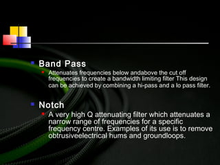
![Types Of Filters
Hi Pass [Low Cut]
Low Pass [Hi Cut]
Band Pass
Notch](https://image.slidesharecdn.com/equalization-170126173320/85/Equalization-15-320.jpg)
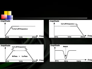
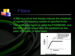
![ Hi Pass [Low Cut]
Attenuates frequencies below the cut off
frequency. Suitable for rolling off low frequency
rumble in the signal source.
Low Pass [Hi Cut]
Attenuates frequencies above the cut off frequency. Suitable
for rolling off higher frequency content of the signal which is
unwanted (i.e. hi frequency rings, etc.)](https://image.slidesharecdn.com/equalization-170126173320/85/Equalization-16-320.jpg)