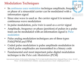
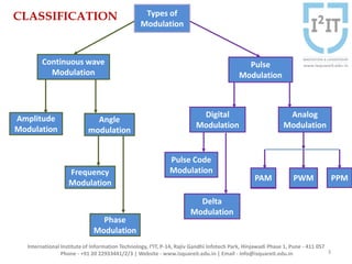
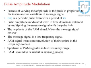
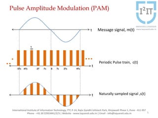
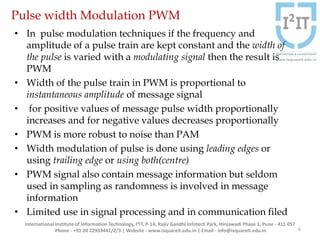
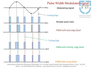
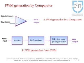
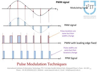
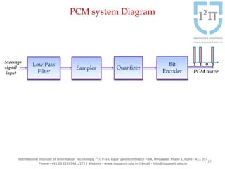
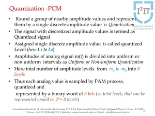
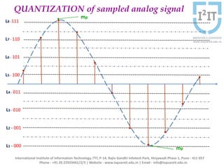
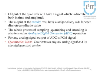
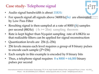
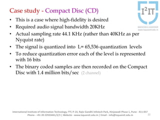
Pulse Modulation
Smita R Kadam
Department of Electronics and Telecommunication
International Institute of Information Technology, I²IT
www.isquareit.edu.in 1
Modulation Techniques
• In continuous wave modulation technique amplitude, frequency
or phase of a sinusoidal carrier can be modulated with a
information signal
• Since sine wave is used as the carrier signal it is termed as
continuous wave modulation
• In pulse modulation, pulse train is used as a carrier signal
• Amplitude, frequency or phase (position) of pulses in a pulse
train can be modulated with an information signal is Pulse
modulation
• Pulse analog modulation techniques are of three types
PAM,PWM and PPM
• Coded pulse modulation is pulse amplitude modulation in
which pulse amplitudes are transmitted in a binary code
• Fundamental and most important pulse digital modulation
technique is the Pulse code Modulation (PCM)
2
International Institute of Information Technology, I²IT, P-14, Rajiv Gandhi Infotech Park, Hinjawadi Phase 1, Pune - 411 057
Phone - +91 20 22933441/2/3 | Website - www.isquareit.edu.in | Email - info@isquareit.edu.in
Types of
Modulation
Pulse Code
ModulationFrequency
Modulation
Analog
Modulation
Digital
Modulation
Angle
modulation
Amplitude
Modulation
Pulse
Modulation
Continuous wave
Modulation
Delta
Modulation
PWM PPMPAM
Phase
Modulation
PWMPAM
CLASSIFICATION
3
International Institute of Information Technology, I²IT, P-14, Rajiv Gandhi Infotech Park, Hinjawadi Phase 1, Pune - 411 057
Phone - +91 20 22933441/2/3 | Website - www.isquareit.edu.in | Email - info@isquareit.edu.in
Pulse Amplitude Modulation
• Process of varying the amplitude of the pulse in proportion to
the instantaneous variations of message signal
• C(t) is a periodic pulse train with a period of Ts
• Pulse amplitude modulated wave in time domain is obtained
by multiplying the message signal with the pulse train
• The amplitude of the PAM signal follows the message signal
contour
• The message signal is a low frequency signal
• PAM signal results in convolution of their spectra in the
frequency domain
• Spectrum of PAM signal is in low frequency range
• PAM is found to be useful in sampling process
4
International Institute of Information Technology, I²IT, P-14, Rajiv Gandhi Infotech Park, Hinjawadi Phase 1, Pune - 411 057
Phone - +91 20 22933441/2/3 | Website - www.isquareit.edu.in | Email - info@isquareit.edu.in
Pulse Amplitude Modulation (PAM)
5
Message signal, m(t)
Periodic Pulse train, c(t)
Naturally sampled signal ,s(t)
-5Ts -4Ts -2T -Ts 0 Ts 2Ts 4Ts
τ
International Institute of Information Technology, I²IT, P-14, Rajiv Gandhi Infotech Park, Hinjawadi Phase 1, Pune - 411 057
Phone - +91 20 22933441/2/3 | Website - www.isquareit.edu.in | Email - info@isquareit.edu.in
t
t
t
Pulse width Modulation PWM
• In pulse modulation techniques if the frequency and
amplitude of a pulse train are kept constant and the width of
the pulse is varied with a modulating signal then the result is
PWM
• Width of the pulse train in PWM is proportional to
instantaneous amplitude of message signal
• for positive values of message pulse width proportionally
increases and for negative values decreases proportionally
• PWM is more robust to noise than PAM
• Width modulation of pulse is done using leading edges or
using trailing edge or using both(centre)
• PWM signal also contain message information but seldom
used in sampling as randomness is involved in message
information
• Limited use in signal processing and in communication filed
6
International Institute of Information Technology, I²IT, P-14, Rajiv Gandhi Infotech Park, Hinjawadi Phase 1, Pune - 411 057
Phone - +91 20 22933441/2/3 | Website - www.isquareit.edu.in | Email - info@isquareit.edu.in
International Institute of Information Technology, I²IT, P-14, Rajiv Gandhi Infotech Park, Hinjawadi Phase 1, Pune - 411 057
Phone - +91 20 22933441/2/3 | Website - www.isquareit.edu.in | Email - info@isquareit.edu.in 7
Pulse Width Modulated signal
Modulating Signal
PWM with lead edge fixed
PWM with trailing edge fixed
PWM with centre fixed
Periodic pulse train
t
t
t
t
t
Leading Edge
Trailing Edge
PWM generation by Comparator
8
International Institute of Information Technology, I²IT, P-14, Rajiv Gandhi Infotech Park, Hinjawadi Phase 1, Pune - 411 057
Phone - +91 20 22933441/2/3 | Website - www.isquareit.edu.in | Email - info@isquareit.edu.in
PPM
output
PWM
input
PWM
output
Input message
Saw tooth
-
+
b. PPM generation from PWM
a. PWM generation by a Comparator
PWM generator
• A comparator is given two inputs, message signal and carrier
signal
• Maximum of the input signal, should be less than carrier then
PWM is generated at the output of comparator
• Minimum of carrier should be less than minimum of message
signal
• When positive of comparator is at higher potential output is
positive and
• When negative of comparator is at higher potential output is
negative
• Duration for which comparator stays high is dependent on
input signal magnitude and this decides width of pulse
generated
• Thus width of the pulse generated at its output is
proportional to the amplitude of message signal at that instant
9
International Institute of Information Technology, I²IT, P-14, Rajiv Gandhi Infotech Park, Hinjawadi Phase 1, Pune - 411 057
Phone - +91 20 22933441/2/3 | Website - www.isquareit.edu.in | Email - info@isquareit.edu.in
PPM Generation
• PWM generated signal is sent to an inverter to reverses
polarity of the pulses
• Differentiator will generate positive spikes where original
PWM signal was going from HIGH to LOW and
Negative spikes where LOW to HIGH transition
• Positive edge triggered pulse generator ,generates pulses of fixed
width when a positive spike appears , coinciding with falling
edge of original PWM
• PPM outputs where positions of pulses carry input message
information
• Randomness of the width in PWM and randomness in position
of pulse in PPM do not make them suitable for time division
multiplexing scheme
International Institute of Information Technology, I²IT, P-14, Rajiv Gandhi Infotech Park, Hinjawadi Phase 1, Pune - 411 057
Phone - +91 20 22933441/2/3 | Website - www.isquareit.edu.in | Email - info@isquareit.edu.in
10
PWM application
Speed control of DC motor using PWM:
Speed of DC motor depends on the average DC voltage applied
across its terminals
Case
‘V ‘ volts is the voltage for running the DC motor
‘0’ volts rest condition for DC motor
Now speed of DC motor can be varied from rest to full speed
value by varying the DC voltage controlled by PWM
PWM provides a convenient and efficient approach for the
speed control of DC motor
refer the link https://youtu.be/3To3Zgr1Jao to learn execution of this
project
11
International Institute of Information Technology, I²IT, P-14, Rajiv Gandhi Infotech Park, Hinjawadi Phase 1, Pune - 411 057
Phone - +91 20 22933441/2/3 | Website - www.isquareit.edu.in | Email - info@isquareit.edu.in
Pulse Position Modulation (PPM)
• Process of varying the position of the pulse with respect to the
instantaneous variations of the message signal
• If ‘tp‘ indicates the timing instant of the leading or trailing
edge of the pulse in each period of the pulse train, In PPM
tp α vm
• Mathematically position of the leading or trailing edge of the
pulse in PPM signal is given by
tp = f(vm ) position of pulse is function of message
signal instantaneous amplitude
• When there is no message, position of leading/trailing edge
of the pulse is equal to the original position tp = 0
• For positive values of message , the position will be
proportionately shifted right
• For negative values of message, the position will be
proportionately shifted left
12
International Institute of Information Technology, I²IT, P-14, Rajiv Gandhi Infotech Park, Hinjawadi Phase 1, Pune - 411 057
Phone - +91 20 22933441/2/3 | Website - www.isquareit.edu.in | Email - info@isquareit.edu.in
13
PWM signal
Modulating Signal
PWM with leading edge fixed
PAM signal
Pulse locations are
same but their
widths change
Pulse widths are
same but their
locations change
PPM Signal
t
t
t
t
Pulse Modulation Techniques
International Institute of Information Technology, I²IT, P-14, Rajiv Gandhi Infotech Park, Hinjawadi Phase 1, Pune - 411 057
Phone - +91 20 22933441/2/3 | Website - www.isquareit.edu.in | Email - info@isquareit.edu.in
Demodulation of Pulse amplitude Modulated Signals
• PPM can be generated by processing PWM
• Edge of the PWM waveform is detected to get position of the
pulse in each period
• PWM can be generated by processing PPM
• PAM,PWM and PPM stores the message in the baseband itself
• The message information here is represented at discrete instants
of time
• Demodulator can reconstruct the approximate version of the
continuous time signal
• When PAM input is passed through Low Pass Filter , it retains
low frequency information and smoothes out the pulse train
information
• PWM and PPM signals are first converted into PAM and then
perform low pass filtering
International Institute of Information Technology, I²IT, P-14, Rajiv Gandhi Infotech Park, Hinjawadi Phase 1, Pune - 411 057
Phone - +91 20 22933441/2/3 | Website - www.isquareit.edu.in | Email - info@isquareit.edu.in
14
Demodulation of Pulse Analog Modulated Signals
International Institute of Information Technology, I²IT, P-14, Rajiv Gandhi Infotech Park, Hinjawadi Phase 1, Pune - 411 057
Phone - +91 20 22933441/2/3 | Website - www.isquareit.edu.in | Email - info@isquareit.edu.in
15
PWM
Message
signal
PPM
Message
signal
PAM
Pulse Code Modulation (PCM)
• The fundamental and most important pulse digital
modulation technique is the Pulse Code Modulation
• In PAM amplitude can take on any value over a continuous
range
• Digital signal amplitude can take on only a finite number of
values
• PCM represents each discrete amplitude level by a binary code
• PCM is a tool for converting Analog signal into Digital signal
(ADC)
• Low Pass Filter also acts as a anti aliasing filter
• Sampler block essentially performs PAM process
• Input of the sampler block is a signal which is continuous in
time and amplitude
• While output of sampler has a signal which is discrete in
time and continuous in amplitude (value)
International Institute of Information Technology, I²IT, P-14, Rajiv Gandhi Infotech Park, Hinjawadi Phase 1, Pune - 411 057
Phone - +91 20 22933441/2/3 | Website - www.isquareit.edu.in | Email - info@isquareit.edu.in
16
PCM system Diagram
International Institute of Information Technology, I²IT, P-14, Rajiv Gandhi Infotech Park, Hinjawadi Phase 1, Pune - 411 057
Phone - +91 20 22933441/2/3 | Website - www.isquareit.edu.in | Email - info@isquareit.edu.in
17
Message
signal
input
1 1 0 1
PCM wave
Quantization -PCM
• Round a group of nearby amplitude values and represent
them by a single discrete amplitude value is Quantization
• The signal with discretized amplitude values is termed as
Quantized signal
• Assigned single discrete amplitude value is called quantized
Level (here L1 to L8)
• Amplitudes of analog signal m(t) is divided into uniform or
non uniform intervals as Uniform or Non-uniform Quantization
• Here total number of amplitude levels from mp to -mp into 8
levels
• Thus each analog value is sampled by PAM process,
quantized and
represented by a binary word of 3 bits (so total levels that can be
represented would be 23= 8 levels)
International Institute of Information Technology, I²IT, P-14, Rajiv Gandhi Infotech Park, Hinjawadi Phase 1, Pune - 411 057
Phone - +91 20 22933441/2/3 | Website - www.isquareit.edu.in | Email - info@isquareit.edu.in
18
International Institute of Information Technology, I²IT, P-14, Rajiv Gandhi Infotech Park, Hinjawadi Phase 1, Pune - 411 057
Phone - +91 20 22933441/2/3 | Website - www.isquareit.edu.in | Email - info@isquareit.edu.in
L4 - 011
L3 - 010
L2 - 001
L1 - 000
L8 -111
L7 - 110
L6 - 101
L5 - 100
QUANTIZATION of sampled analog signal
mp
mp
• Output of the quantizer will have a signal which is discrete
both in time and amplitude
• The output of the encoder will have a unique binary code for each
discrete amplitude value
• The whole process of sampling , quantizing and encoding is
also termed as Analog to Digital Conversion (ADC) operation
• For any analog signal output of ADC is PCM signal
• Quantization Noise : Error between original analog signal and its
allocated quantized version
International Institute of Information Technology, I²IT, P-14, Rajiv Gandhi Infotech Park, Hinjawadi Phase 1, Pune - 411 057
Phone - +91 20 22933441/2/3 | Website - www.isquareit.edu.in | Email - info@isquareit.edu.in 20
Case study- Telephone signal
• Audio signal bandwidth is about 15KHz
• For speech signal all signals above 3400Hz(fm) are eliminated
by Low Pass Filter
• Resulting signal is then sampled at a rate of 8000 (fs) samples
per second (8KHz) ( fs >= 2fm) sampling theorem
• Rate is kept higher than Nyquist sampling rate of 6.8KHz so
that realizable filters can be applied for signal reconstruction
• Quantization levels are 256 (L-256)
• 256 levels means each level requires a group of 8 binary pulses
to encode each sample (28=256)
• Each sample in this example is encoded by 8 binary bits
• Thus, a telephone signal requires 8 x 8000 = 64,000 binary
pulses per second
International Institute of Information Technology, I²IT, P-14, Rajiv Gandhi Infotech Park, Hinjawadi Phase 1, Pune - 411 057
Phone - +91 20 22933441/2/3 | Website - www.isquareit.edu.in | Email - info@isquareit.edu.in
21
Case study - Compact Disc (CD)
• This is a case where high-fidelity is desired
• Required audio signal bandwidth 20KHz
• Actual sampling rate 44.1 KHz (rather than 40KHz as per
Nyquist rate)
• The signal is quantized into L= 65,536 quantization levels
• To reduce quantization error each of the level is represented
with 16 bits
• The binary coded samples are then recorded on the Compact
Disc with 1.4 million bits/sec (2 channel)
International Institute of Information Technology, I²IT, P-14, Rajiv Gandhi Infotech Park, Hinjawadi Phase 1, Pune - 411 057
Phone - +91 20 22933441/2/3 | Website - www.isquareit.edu.in | Email - info@isquareit.edu.in 22
References
• R Taub, D Schilling and G Saha, Principles of Communication Systems,
3rd edition, Mc Graw Hill, 2012
• D Roddy, J Coolen, Electronic Communication, 4th edition, Pearson,
2011
• G Kennedy, B Davis, S R M Prasanna, Electronic Communication
Syatems,5 th edition, Mc Graw Hill, 2011
• B P Lathi, Zhi Ding, Modern Digital and Analog Communication
systems, 4th edition
23
International Institute of Information Technology, I²IT, P-14, Rajiv Gandhi Infotech Park, Hinjawadi Phase 1, Pune - 411 057
Phone - +91 20 22933441/2/3 | Website - www.isquareit.edu.in | Email - info@isquareit.edu.in
Thank You!!
For any queries
Website: http://www.isquareit.edu.in/
Contact: smitak@isquareit.edu.in
24
International Institute of Information Technology, I²IT, P-14, Rajiv Gandhi Infotech Park, Hinjawadi Phase 1, Pune - 411 057
Phone - +91 20 22933441/2/3 | Website - www.isquareit.edu.in | Email - info@isquareit.edu.in

Pulse Modulation - Classification & Case Study

  • 1.
    Pulse Modulation Smita RKadam Department of Electronics and Telecommunication International Institute of Information Technology, I²IT www.isquareit.edu.in 1
  • 2.
    Modulation Techniques • Incontinuous wave modulation technique amplitude, frequency or phase of a sinusoidal carrier can be modulated with a information signal • Since sine wave is used as the carrier signal it is termed as continuous wave modulation • In pulse modulation, pulse train is used as a carrier signal • Amplitude, frequency or phase (position) of pulses in a pulse train can be modulated with an information signal is Pulse modulation • Pulse analog modulation techniques are of three types PAM,PWM and PPM • Coded pulse modulation is pulse amplitude modulation in which pulse amplitudes are transmitted in a binary code • Fundamental and most important pulse digital modulation technique is the Pulse code Modulation (PCM) 2 International Institute of Information Technology, I²IT, P-14, Rajiv Gandhi Infotech Park, Hinjawadi Phase 1, Pune - 411 057 Phone - +91 20 22933441/2/3 | Website - www.isquareit.edu.in | Email - info@isquareit.edu.in
  • 3.
    Types of Modulation Pulse Code ModulationFrequency Modulation Analog Modulation Digital Modulation Angle modulation Amplitude Modulation Pulse Modulation Continuouswave Modulation Delta Modulation PWM PPMPAM Phase Modulation PWMPAM CLASSIFICATION 3 International Institute of Information Technology, I²IT, P-14, Rajiv Gandhi Infotech Park, Hinjawadi Phase 1, Pune - 411 057 Phone - +91 20 22933441/2/3 | Website - www.isquareit.edu.in | Email - info@isquareit.edu.in
  • 4.
    Pulse Amplitude Modulation •Process of varying the amplitude of the pulse in proportion to the instantaneous variations of message signal • C(t) is a periodic pulse train with a period of Ts • Pulse amplitude modulated wave in time domain is obtained by multiplying the message signal with the pulse train • The amplitude of the PAM signal follows the message signal contour • The message signal is a low frequency signal • PAM signal results in convolution of their spectra in the frequency domain • Spectrum of PAM signal is in low frequency range • PAM is found to be useful in sampling process 4 International Institute of Information Technology, I²IT, P-14, Rajiv Gandhi Infotech Park, Hinjawadi Phase 1, Pune - 411 057 Phone - +91 20 22933441/2/3 | Website - www.isquareit.edu.in | Email - info@isquareit.edu.in
  • 5.
    Pulse Amplitude Modulation(PAM) 5 Message signal, m(t) Periodic Pulse train, c(t) Naturally sampled signal ,s(t) -5Ts -4Ts -2T -Ts 0 Ts 2Ts 4Ts τ International Institute of Information Technology, I²IT, P-14, Rajiv Gandhi Infotech Park, Hinjawadi Phase 1, Pune - 411 057 Phone - +91 20 22933441/2/3 | Website - www.isquareit.edu.in | Email - info@isquareit.edu.in t t t
  • 6.
    Pulse width ModulationPWM • In pulse modulation techniques if the frequency and amplitude of a pulse train are kept constant and the width of the pulse is varied with a modulating signal then the result is PWM • Width of the pulse train in PWM is proportional to instantaneous amplitude of message signal • for positive values of message pulse width proportionally increases and for negative values decreases proportionally • PWM is more robust to noise than PAM • Width modulation of pulse is done using leading edges or using trailing edge or using both(centre) • PWM signal also contain message information but seldom used in sampling as randomness is involved in message information • Limited use in signal processing and in communication filed 6 International Institute of Information Technology, I²IT, P-14, Rajiv Gandhi Infotech Park, Hinjawadi Phase 1, Pune - 411 057 Phone - +91 20 22933441/2/3 | Website - www.isquareit.edu.in | Email - info@isquareit.edu.in
  • 7.
    International Institute ofInformation Technology, I²IT, P-14, Rajiv Gandhi Infotech Park, Hinjawadi Phase 1, Pune - 411 057 Phone - +91 20 22933441/2/3 | Website - www.isquareit.edu.in | Email - info@isquareit.edu.in 7 Pulse Width Modulated signal Modulating Signal PWM with lead edge fixed PWM with trailing edge fixed PWM with centre fixed Periodic pulse train t t t t t Leading Edge Trailing Edge
  • 8.
    PWM generation byComparator 8 International Institute of Information Technology, I²IT, P-14, Rajiv Gandhi Infotech Park, Hinjawadi Phase 1, Pune - 411 057 Phone - +91 20 22933441/2/3 | Website - www.isquareit.edu.in | Email - info@isquareit.edu.in PPM output PWM input PWM output Input message Saw tooth - + b. PPM generation from PWM a. PWM generation by a Comparator
  • 9.
    PWM generator • Acomparator is given two inputs, message signal and carrier signal • Maximum of the input signal, should be less than carrier then PWM is generated at the output of comparator • Minimum of carrier should be less than minimum of message signal • When positive of comparator is at higher potential output is positive and • When negative of comparator is at higher potential output is negative • Duration for which comparator stays high is dependent on input signal magnitude and this decides width of pulse generated • Thus width of the pulse generated at its output is proportional to the amplitude of message signal at that instant 9 International Institute of Information Technology, I²IT, P-14, Rajiv Gandhi Infotech Park, Hinjawadi Phase 1, Pune - 411 057 Phone - +91 20 22933441/2/3 | Website - www.isquareit.edu.in | Email - info@isquareit.edu.in
  • 10.
    PPM Generation • PWMgenerated signal is sent to an inverter to reverses polarity of the pulses • Differentiator will generate positive spikes where original PWM signal was going from HIGH to LOW and Negative spikes where LOW to HIGH transition • Positive edge triggered pulse generator ,generates pulses of fixed width when a positive spike appears , coinciding with falling edge of original PWM • PPM outputs where positions of pulses carry input message information • Randomness of the width in PWM and randomness in position of pulse in PPM do not make them suitable for time division multiplexing scheme International Institute of Information Technology, I²IT, P-14, Rajiv Gandhi Infotech Park, Hinjawadi Phase 1, Pune - 411 057 Phone - +91 20 22933441/2/3 | Website - www.isquareit.edu.in | Email - info@isquareit.edu.in 10
  • 11.
    PWM application Speed controlof DC motor using PWM: Speed of DC motor depends on the average DC voltage applied across its terminals Case ‘V ‘ volts is the voltage for running the DC motor ‘0’ volts rest condition for DC motor Now speed of DC motor can be varied from rest to full speed value by varying the DC voltage controlled by PWM PWM provides a convenient and efficient approach for the speed control of DC motor refer the link https://youtu.be/3To3Zgr1Jao to learn execution of this project 11 International Institute of Information Technology, I²IT, P-14, Rajiv Gandhi Infotech Park, Hinjawadi Phase 1, Pune - 411 057 Phone - +91 20 22933441/2/3 | Website - www.isquareit.edu.in | Email - info@isquareit.edu.in
  • 12.
    Pulse Position Modulation(PPM) • Process of varying the position of the pulse with respect to the instantaneous variations of the message signal • If ‘tp‘ indicates the timing instant of the leading or trailing edge of the pulse in each period of the pulse train, In PPM tp α vm • Mathematically position of the leading or trailing edge of the pulse in PPM signal is given by tp = f(vm ) position of pulse is function of message signal instantaneous amplitude • When there is no message, position of leading/trailing edge of the pulse is equal to the original position tp = 0 • For positive values of message , the position will be proportionately shifted right • For negative values of message, the position will be proportionately shifted left 12 International Institute of Information Technology, I²IT, P-14, Rajiv Gandhi Infotech Park, Hinjawadi Phase 1, Pune - 411 057 Phone - +91 20 22933441/2/3 | Website - www.isquareit.edu.in | Email - info@isquareit.edu.in
  • 13.
    13 PWM signal Modulating Signal PWMwith leading edge fixed PAM signal Pulse locations are same but their widths change Pulse widths are same but their locations change PPM Signal t t t t Pulse Modulation Techniques International Institute of Information Technology, I²IT, P-14, Rajiv Gandhi Infotech Park, Hinjawadi Phase 1, Pune - 411 057 Phone - +91 20 22933441/2/3 | Website - www.isquareit.edu.in | Email - info@isquareit.edu.in
  • 14.
    Demodulation of Pulseamplitude Modulated Signals • PPM can be generated by processing PWM • Edge of the PWM waveform is detected to get position of the pulse in each period • PWM can be generated by processing PPM • PAM,PWM and PPM stores the message in the baseband itself • The message information here is represented at discrete instants of time • Demodulator can reconstruct the approximate version of the continuous time signal • When PAM input is passed through Low Pass Filter , it retains low frequency information and smoothes out the pulse train information • PWM and PPM signals are first converted into PAM and then perform low pass filtering International Institute of Information Technology, I²IT, P-14, Rajiv Gandhi Infotech Park, Hinjawadi Phase 1, Pune - 411 057 Phone - +91 20 22933441/2/3 | Website - www.isquareit.edu.in | Email - info@isquareit.edu.in 14
  • 15.
    Demodulation of PulseAnalog Modulated Signals International Institute of Information Technology, I²IT, P-14, Rajiv Gandhi Infotech Park, Hinjawadi Phase 1, Pune - 411 057 Phone - +91 20 22933441/2/3 | Website - www.isquareit.edu.in | Email - info@isquareit.edu.in 15 PWM Message signal PPM Message signal PAM
  • 16.
    Pulse Code Modulation(PCM) • The fundamental and most important pulse digital modulation technique is the Pulse Code Modulation • In PAM amplitude can take on any value over a continuous range • Digital signal amplitude can take on only a finite number of values • PCM represents each discrete amplitude level by a binary code • PCM is a tool for converting Analog signal into Digital signal (ADC) • Low Pass Filter also acts as a anti aliasing filter • Sampler block essentially performs PAM process • Input of the sampler block is a signal which is continuous in time and amplitude • While output of sampler has a signal which is discrete in time and continuous in amplitude (value) International Institute of Information Technology, I²IT, P-14, Rajiv Gandhi Infotech Park, Hinjawadi Phase 1, Pune - 411 057 Phone - +91 20 22933441/2/3 | Website - www.isquareit.edu.in | Email - info@isquareit.edu.in 16
  • 17.
    PCM system Diagram InternationalInstitute of Information Technology, I²IT, P-14, Rajiv Gandhi Infotech Park, Hinjawadi Phase 1, Pune - 411 057 Phone - +91 20 22933441/2/3 | Website - www.isquareit.edu.in | Email - info@isquareit.edu.in 17 Message signal input 1 1 0 1 PCM wave
  • 18.
    Quantization -PCM • Rounda group of nearby amplitude values and represent them by a single discrete amplitude value is Quantization • The signal with discretized amplitude values is termed as Quantized signal • Assigned single discrete amplitude value is called quantized Level (here L1 to L8) • Amplitudes of analog signal m(t) is divided into uniform or non uniform intervals as Uniform or Non-uniform Quantization • Here total number of amplitude levels from mp to -mp into 8 levels • Thus each analog value is sampled by PAM process, quantized and represented by a binary word of 3 bits (so total levels that can be represented would be 23= 8 levels) International Institute of Information Technology, I²IT, P-14, Rajiv Gandhi Infotech Park, Hinjawadi Phase 1, Pune - 411 057 Phone - +91 20 22933441/2/3 | Website - www.isquareit.edu.in | Email - info@isquareit.edu.in 18
  • 19.
    International Institute ofInformation Technology, I²IT, P-14, Rajiv Gandhi Infotech Park, Hinjawadi Phase 1, Pune - 411 057 Phone - +91 20 22933441/2/3 | Website - www.isquareit.edu.in | Email - info@isquareit.edu.in L4 - 011 L3 - 010 L2 - 001 L1 - 000 L8 -111 L7 - 110 L6 - 101 L5 - 100 QUANTIZATION of sampled analog signal mp mp
  • 20.
    • Output ofthe quantizer will have a signal which is discrete both in time and amplitude • The output of the encoder will have a unique binary code for each discrete amplitude value • The whole process of sampling , quantizing and encoding is also termed as Analog to Digital Conversion (ADC) operation • For any analog signal output of ADC is PCM signal • Quantization Noise : Error between original analog signal and its allocated quantized version International Institute of Information Technology, I²IT, P-14, Rajiv Gandhi Infotech Park, Hinjawadi Phase 1, Pune - 411 057 Phone - +91 20 22933441/2/3 | Website - www.isquareit.edu.in | Email - info@isquareit.edu.in 20
  • 21.
    Case study- Telephonesignal • Audio signal bandwidth is about 15KHz • For speech signal all signals above 3400Hz(fm) are eliminated by Low Pass Filter • Resulting signal is then sampled at a rate of 8000 (fs) samples per second (8KHz) ( fs >= 2fm) sampling theorem • Rate is kept higher than Nyquist sampling rate of 6.8KHz so that realizable filters can be applied for signal reconstruction • Quantization levels are 256 (L-256) • 256 levels means each level requires a group of 8 binary pulses to encode each sample (28=256) • Each sample in this example is encoded by 8 binary bits • Thus, a telephone signal requires 8 x 8000 = 64,000 binary pulses per second International Institute of Information Technology, I²IT, P-14, Rajiv Gandhi Infotech Park, Hinjawadi Phase 1, Pune - 411 057 Phone - +91 20 22933441/2/3 | Website - www.isquareit.edu.in | Email - info@isquareit.edu.in 21
  • 22.
    Case study -Compact Disc (CD) • This is a case where high-fidelity is desired • Required audio signal bandwidth 20KHz • Actual sampling rate 44.1 KHz (rather than 40KHz as per Nyquist rate) • The signal is quantized into L= 65,536 quantization levels • To reduce quantization error each of the level is represented with 16 bits • The binary coded samples are then recorded on the Compact Disc with 1.4 million bits/sec (2 channel) International Institute of Information Technology, I²IT, P-14, Rajiv Gandhi Infotech Park, Hinjawadi Phase 1, Pune - 411 057 Phone - +91 20 22933441/2/3 | Website - www.isquareit.edu.in | Email - info@isquareit.edu.in 22
  • 23.
    References • R Taub,D Schilling and G Saha, Principles of Communication Systems, 3rd edition, Mc Graw Hill, 2012 • D Roddy, J Coolen, Electronic Communication, 4th edition, Pearson, 2011 • G Kennedy, B Davis, S R M Prasanna, Electronic Communication Syatems,5 th edition, Mc Graw Hill, 2011 • B P Lathi, Zhi Ding, Modern Digital and Analog Communication systems, 4th edition 23 International Institute of Information Technology, I²IT, P-14, Rajiv Gandhi Infotech Park, Hinjawadi Phase 1, Pune - 411 057 Phone - +91 20 22933441/2/3 | Website - www.isquareit.edu.in | Email - info@isquareit.edu.in
  • 24.
    Thank You!! For anyqueries Website: http://www.isquareit.edu.in/ Contact: smitak@isquareit.edu.in 24 International Institute of Information Technology, I²IT, P-14, Rajiv Gandhi Infotech Park, Hinjawadi Phase 1, Pune - 411 057 Phone - +91 20 22933441/2/3 | Website - www.isquareit.edu.in | Email - info@isquareit.edu.in

Editor's Notes