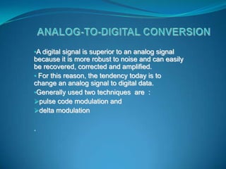
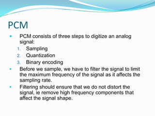
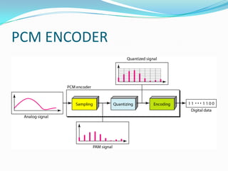
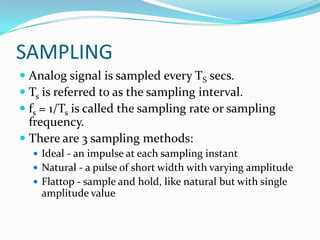
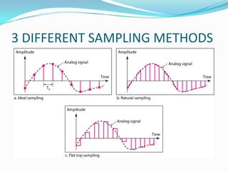
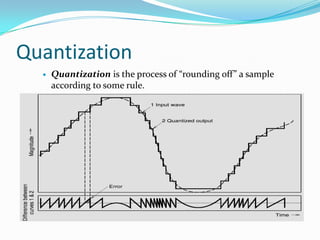
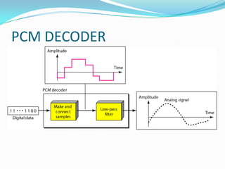
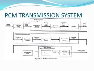
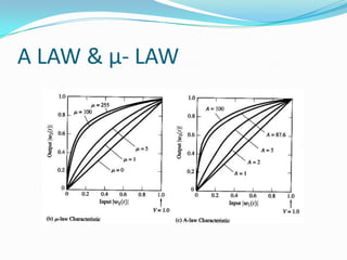
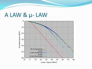
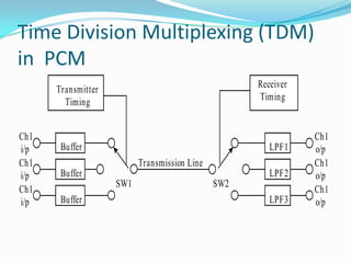
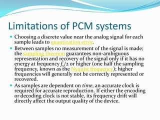
BY : MS. SURABHI TANKKAR
          ME ETRX
•A digital signal is superior to an analog signal
because it is more robust to noise and can easily
be recovered, corrected and amplified.
• For this reason, the tendency today is to
change an analog signal to digital data.
•Generally used two techniques are :
pulse code modulation and
delta modulation

.
PCM
    PCM consists of three steps to digitize an analog
     signal:
    1. Sampling
    2. Quantization
    3. Binary encoding
    Before we sample, we have to filter the signal to limit
     the maximum frequency of the signal as it affects the
     sampling rate.
    Filtering should ensure that we do not distort the
     signal, ie remove high frequency components that
     affect the signal shape.
PCM ENCODER
SAMPLING
 Analog signal is sampled every TS secs.
 Ts is referred to as the sampling interval.
 fs = 1/Ts is called the sampling rate or sampling
  frequency.
 There are 3 sampling methods:
   Ideal - an impulse at each sampling instant
   Natural - a pulse of short width with varying amplitude
   Flattop - sample and hold, like natural but with single
    amplitude value
3 DIFFERENT SAMPLING METHODS
Quantization
     Quantization is the process of “rounding off” a sample
      according to some rule.
Nonuniform Quantizing
 Voice analog signals are more likely to have
  amplitude values near zero than at the extreme peak
  values allowed.
 For signals with nonuniform amplitude distribution,
  the granular quantizing noise will be a serious
  problem if the step size is not reduced for amplitude
  values near zero and increased for extremely large
  values. This is called nonuniform quantizing since a
  variable step size is used.
Encoding

 Encoding is the process of representing the sampled
  values as a binary number in the range 0 to n.
 The value of n is chosen as a power of 2, depending on
  the accuracy required.
 Increasing n reduces the step size between adjacent
  Quantization levels and hence reduces the
  Quantization noise.
 The down side of this is that the amount of digital
  data required to represent the analog signal increases.
Quantization Error and SNQR
 When a signal is quantized, we introduce an error - the coded signal
    is an approximation of the actual amplitude value.
   The difference between actual and coded value (midpoint) is referred
    to as the quantization error.
   Signals with lower amplitude values will suffer more from
    quantization error as the error range: /2, is fixed for all signal levels.
   Non linear quantization is used to alleviate this problem. Goal is to
    keep SNQR fixed for all sample values.
   Two approaches:
      The quantization levels follow a logarithmic curve. Smaller ’s at
        lower amplitudes and larger ’s at higher amplitudes.
      Companding: The sample values are compressed at the sender
        into logarithmic zones, and then expanded at the receiver. The
        zon
PCM DECODER
PCM DECODER
 To recover an analog signal from a digitized signal
  we follow the following steps:
   We use a hold circuit that holds the amplitude value of a
    pulse till the next pulse arrives.
   We pass this signal through a low pass filter with a cutoff
    frequency that is equal to the highest frequency in the
    pre-sampled signal.
PCM TRANSMISSION SYSTEM
Companding

 In telecommunication, signalprocessing,
 companding (occasionally called compansion) is a
 method of mitigating the detrimental effects of a
 channel with limited dynamic range.
 The name is a portmanteau of compressing and
 expanding
A LAW & µ- LAW
A LAW & µ- LAW
Speech Companding

 The human auditory system is believed to be a
  logarithmic process in which high amplitude sounds
  do not require the same resolution as low amplitude
  sounds.
 The human ear is more sensitive to quantization noise
  in small signals than large signals.
 A-law and µ-law coding apply a logarithmic
  quantization function to adjust the data resolution in
  proportion to the level of the input signal.
Differential Pulse Code Modulation
(DPCM)


 quantises the difference between the original and the
  predicted signals, i.e. the difference between successive
  values.
 Leads to reduction in the number of bits used per sample
  over that used for PCM. Using DPCM can reduce the bit
  rate of voice transmission down to 48 kbps.
 DPCM can be described as a predictive coding scheme.
Adaptive Differential Pulse Code Modulation
(ADPCM)

 ADPCM adapts the Quantization levels of the
  difference signal that is generated during the DPCM
  process.
 If the difference signal is low, ADPCM reduces the size
  of the Quantization levels.
 If the difference signal is high, ADPCM increases the
  size of the Quantization levels.
 The Quantization level is thus adapted to the size of
  the input difference signal, generating a uniform
  signal-to-noise ratio throughout the dynamic range of
  the difference signal.
Time Division Multiplexing (TDM)
in PCM
      Transmitter                                   Receiver
        Timing                                      Timing


Ch1                                                            Ch1
i/p    Buffer                                          LPF1    o/p
Ch1                       Transmission Line                    Ch1
i/p    Buffer                                          LPF2    o/p
                    SW1                       SW2
Ch1                                                            Ch1
i/p    Buffer                                          LPF3    o/p
Applications of PCM-TDM systems
 TDM and Codecs
 Digital Transmission Hierarchies
 Plesiochronous Digital Hierarchy (PDH)
Limitations of PCM systems
 Choosing a discrete value near the analog signal for each
  sample leads to quantization error.
 Between samples no measurement of the signal is made;
  the sampling theorem guarantees non-ambiguous
  representation and recovery of the signal only if it has no
  energy at frequency fs/2 or higher (one half the sampling
  frequency, known as the Nyquist frequency); higher
  frequencies will generally not be correctly represented or
  recovered.
 As samples are dependent on time, an accurate clock is
  required for accurate reproduction. If either the encoding
  or decoding clock is not stable, its frequency drift will
  directly affect the output quality of the device.
THANK YOU

Presentation ct

  • 1.
    BY : MS.SURABHI TANKKAR ME ETRX
  • 2.
    •A digital signalis superior to an analog signal because it is more robust to noise and can easily be recovered, corrected and amplified. • For this reason, the tendency today is to change an analog signal to digital data. •Generally used two techniques are : pulse code modulation and delta modulation .
  • 3.
    PCM  PCM consists of three steps to digitize an analog signal: 1. Sampling 2. Quantization 3. Binary encoding  Before we sample, we have to filter the signal to limit the maximum frequency of the signal as it affects the sampling rate.  Filtering should ensure that we do not distort the signal, ie remove high frequency components that affect the signal shape.
  • 4.
  • 5.
    SAMPLING  Analog signalis sampled every TS secs.  Ts is referred to as the sampling interval.  fs = 1/Ts is called the sampling rate or sampling frequency.  There are 3 sampling methods:  Ideal - an impulse at each sampling instant  Natural - a pulse of short width with varying amplitude  Flattop - sample and hold, like natural but with single amplitude value
  • 6.
  • 7.
    Quantization  Quantization is the process of “rounding off” a sample according to some rule.
  • 8.
    Nonuniform Quantizing  Voiceanalog signals are more likely to have amplitude values near zero than at the extreme peak values allowed.  For signals with nonuniform amplitude distribution, the granular quantizing noise will be a serious problem if the step size is not reduced for amplitude values near zero and increased for extremely large values. This is called nonuniform quantizing since a variable step size is used.
  • 9.
    Encoding  Encoding isthe process of representing the sampled values as a binary number in the range 0 to n.  The value of n is chosen as a power of 2, depending on the accuracy required.  Increasing n reduces the step size between adjacent Quantization levels and hence reduces the Quantization noise.  The down side of this is that the amount of digital data required to represent the analog signal increases.
  • 10.
    Quantization Error andSNQR  When a signal is quantized, we introduce an error - the coded signal is an approximation of the actual amplitude value.  The difference between actual and coded value (midpoint) is referred to as the quantization error.  Signals with lower amplitude values will suffer more from quantization error as the error range: /2, is fixed for all signal levels.  Non linear quantization is used to alleviate this problem. Goal is to keep SNQR fixed for all sample values.  Two approaches:  The quantization levels follow a logarithmic curve. Smaller ’s at lower amplitudes and larger ’s at higher amplitudes.  Companding: The sample values are compressed at the sender into logarithmic zones, and then expanded at the receiver. The zon
  • 11.
  • 12.
    PCM DECODER  Torecover an analog signal from a digitized signal we follow the following steps:  We use a hold circuit that holds the amplitude value of a pulse till the next pulse arrives.  We pass this signal through a low pass filter with a cutoff frequency that is equal to the highest frequency in the pre-sampled signal.
  • 13.
  • 14.
    Companding In telecommunication,signalprocessing, companding (occasionally called compansion) is a method of mitigating the detrimental effects of a channel with limited dynamic range. The name is a portmanteau of compressing and expanding
  • 15.
    A LAW &µ- LAW
  • 16.
    A LAW &µ- LAW
  • 17.
    Speech Companding  Thehuman auditory system is believed to be a logarithmic process in which high amplitude sounds do not require the same resolution as low amplitude sounds.  The human ear is more sensitive to quantization noise in small signals than large signals.  A-law and µ-law coding apply a logarithmic quantization function to adjust the data resolution in proportion to the level of the input signal.
  • 18.
    Differential Pulse CodeModulation (DPCM)  quantises the difference between the original and the predicted signals, i.e. the difference between successive values.  Leads to reduction in the number of bits used per sample over that used for PCM. Using DPCM can reduce the bit rate of voice transmission down to 48 kbps.  DPCM can be described as a predictive coding scheme.
  • 19.
    Adaptive Differential PulseCode Modulation (ADPCM)  ADPCM adapts the Quantization levels of the difference signal that is generated during the DPCM process.  If the difference signal is low, ADPCM reduces the size of the Quantization levels.  If the difference signal is high, ADPCM increases the size of the Quantization levels.  The Quantization level is thus adapted to the size of the input difference signal, generating a uniform signal-to-noise ratio throughout the dynamic range of the difference signal.
  • 20.
    Time Division Multiplexing(TDM) in PCM Transmitter Receiver Timing Timing Ch1 Ch1 i/p Buffer LPF1 o/p Ch1 Transmission Line Ch1 i/p Buffer LPF2 o/p SW1 SW2 Ch1 Ch1 i/p Buffer LPF3 o/p
  • 21.
    Applications of PCM-TDMsystems  TDM and Codecs  Digital Transmission Hierarchies  Plesiochronous Digital Hierarchy (PDH)
  • 22.
    Limitations of PCMsystems  Choosing a discrete value near the analog signal for each sample leads to quantization error.  Between samples no measurement of the signal is made; the sampling theorem guarantees non-ambiguous representation and recovery of the signal only if it has no energy at frequency fs/2 or higher (one half the sampling frequency, known as the Nyquist frequency); higher frequencies will generally not be correctly represented or recovered.  As samples are dependent on time, an accurate clock is required for accurate reproduction. If either the encoding or decoding clock is not stable, its frequency drift will directly affect the output quality of the device.
  • 23.