This document discusses pressure relief valves and their design considerations. It covers:
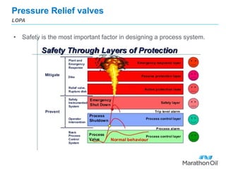
- Safety is the primary factor in designing process systems and relief valves can protect multiple pieces of equipment.
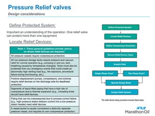
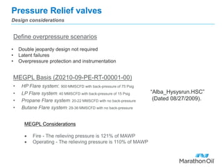
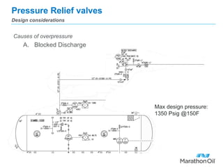
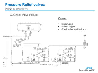
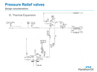
- Relief valves must be sized, located, and designed properly to address overpressure scenarios like blocked discharges, fires, check valve failures, and thermal expansion.
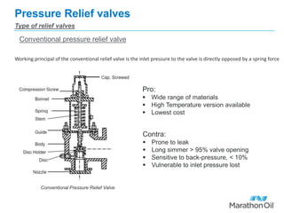
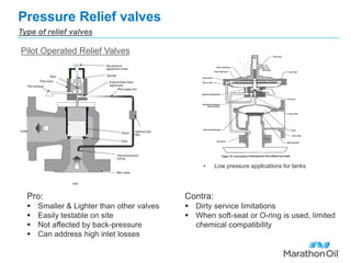
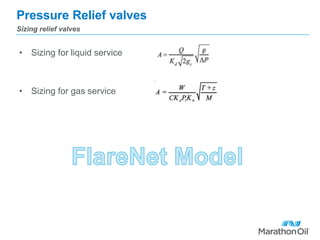
- The document discusses conventional, balanced, and pilot operated relief valve designs and their pros and cons. It also covers sizing relief valves for liquid and gas service and applicable codes and standards.