SlideShare a Scribd company logo
Page 1
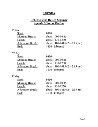
AGENDA
Relief System Design Seminar
Agenda / Course Outline
1st
day
Start: 0800
Morning Break: about 1000-10:15
Lunch: about 1130-1230
Afternoon Break: about 1400-1415 (2 – 2:15 pm)
End: 1630 (4:30 pm)
2nd
day
Start: 0800
Morning Break: about 1000-10:15
Lunch: about 1130-1230
Afternoon Break: about 1400-1415 (2 – 2:15 pm)
End: 1630 (4:30 pm)
3rd
day
Start: 0800
Morning Break: about 1000-10:15
Lunch: about 1130-1230
Afternoon Break: about 1400-1415 (2 – 2:15 pm)
End: 1630 (4:30 pm)
Page 2
PRESSURE RELIEF SYSTEM DESIGN SEMINAR
Seminar objectives:
1. Identify and review the most important aspects of relief system design
2. Familiarize relevant code requirements affecting relief system design
3. Evaluate relationship between design, operating, set, and relieving pressures
4. Review and evaluate overpressure scenarios
5. Provide guidelines for calculating relieving requirements
6. Identify appropriate relieving credits
7. Review single phase (gas or liquid) and multi-phase relief discharge pressure
relief valve sizing equations
8. Evaluate inlet and outlet piping design considerations and equations for single and
multiphase flow
• 3-day seminar (participants can attend for specific areas of interest)
• Seminar can be extended to 4 days where more advanced topics and worked examples are
discussed in depth
Instructor: Ed Zamejc
EZ Relief Systems Consulting, Inc.
edzamejc@ezreliefsystems.com
Cell: (832) 373-7445
Page 3
RELIEF SYSTEM DESIGN COURSE OUTLINE
Follows Relief System Design Guide (available separately - not
included in seminar)
Day 1
1. OVERVIEW OF RELIEF SYSTEM DESIGN
A. Pressure Relief System Design
B. Types of Pressure Relief Devices
C. Documentation Requirements
D. Industry Loss Experience Related to Pressure Relief
Systems
E. Codes and Standards Related to Pressure Relief Systems
(e.g., OSHA, ASME, API, NFPA)
2. SETTING PRESSURE LEVELS
A. Definitions
B. Pressure Relief Device Set Pressures (Code
Requirements)
C. Allowable Pressures during Relief (Code Requirements)
D. Operating Differentials for Pressure Relief Valves
E. Rupture Disk Pressure Settings
F. Temperature Effects on Opening Pressure
G. Vessel Design Pressure versus MAWP
3. OVERPRESSURE SCENARIO SELECTION
A. Introduction
B. Scenario Selection Guidelines
C. Information Needs
D. Scenario Development Process
E. Common Mode Failures
F. Multiple Contingencies/Likelihood Considerations
G. Analysis of 20 Standard Vessel Overpressure Scenarios
[Applied to Site-Specific Example If Possible]
H. Piping
I. Vacuum Causes
J. Scenarios Where Relief Devices do not Generally
Protect
K. Scenarios Where Relief Devices are not Generally
Designed
L. Car-Seal Open/Chain Lock Open Valves
M. Management of Change
(Note: Part of Section 3 may need to be covered in Day 2)
Page 4
Day 2:
(Finish Section 3, as required)
4. RELIEF REQUIREMENT DETERMINATION
A. Information Needs
B. Determining Relief Requirements for 20 Standard
Scenarios - General Considerations, Detailed
Calculations and Emphasis on Site Specific Cases and:
1. Thermal Expansion
2. Pool Fire Exposure
C. Capacity Credits – Allowable and Non-Allowable
D. Alternate Relief Path Credits
E. Single or Multiphase Relief Considerations
5. PRESSURE RELIEF DEVICE SELECTION (OPERATING CHARACTERISTICS)
A. Vents for Low Pressure Service
B. Pressure Relief Valves
1. Spring-Loaded (Conventional and Balanced Bellows)
2. Liquid Certified Valves
3. ASME Section I Steam Valve
4. Pilot-Operated Relief Valves
C. Rupture Disks
D. Rupture Disk/Pressure Relief Valve Combinations
E. Buckling Pins
F. Maintenance aspects (optional)
Day 3:
6. SIZING PRESSURE RELIEF VALVES
A. Origin of Sizing Formulas
B. Single Phase Flow Device Sizing
1. Gas or Vapor Sizing Critical Flow
2. Gas or Vapor Sizing Sub-Critical Flow
3. Non-flashing Liquid Sizing
C. Two-Phase Flow Device Sizing (Omega Method)
1. Two Point Method to Calculate Omega
2. Multiphase Critical Flow Equation
3. Multiphase Sub-Critical Flow Equation
4. Subcooled-Flashing Liquid Sizing
D. Relieving of Fluids above Thermodynamic Critical
Conditions
Page 5
7. RELIEF SYSTEM PIPING DESIGN AND CONSIDERATIONS
A. Piping Design General Considerations
B. Sizing Stand-alone Rupture Disk Relief Systems
C. Pressure Relief Valve Inlet Line Sizing
1. Code Requirements
2. Inlet Pressure Drop Equation (all fluid phases)
3. Options for Handling High Inlet Pressure Loss
D. Pressure Relief Valve Outlet Line Sizing
1. Conventional Versus Balanced Bellows Valves
2. Incompressible Liquid Line Sizing
3. Compressible Gas (vapor) Line Sizing
4. Two Phase Fluid Line Sizing (Omega Method)
E. Piping Layout Considerations
1. Isolation Valves in Relief Systems
2. Relief System Piping Arrangements
3. Brittle Fracture Potential
4. Acoustic-Induced and Turbulence-Induced Fatigue
F. Relief Discharge to Atmosphere
1. General Requirements
2. Atmospheric Discharge of Non-Hazardous Materials
3. Flammable and Toxic Discharge from Atmospheric
Vents
4. Dispersion and Consequence Modeling
8. REACTIVE SYSTEMS
Very brief general discussion
9. RELIEF HEADERS, NETWORKS, AND EFFLUENT HANDLING
A. Scenarios
B. Methodology
C. Knock-out Drums
D. Flare Stacks
1. General Guidelines
2. Thermal Radiation
3. Purging
E. General Discharge Location Considerations
F. Flare Gas Recovery

More Related Content

Viewers also liked

Relief System Design Guide Table of Contents
Relief System Design Guide Table of ContentsRelief System Design Guide Table of Contents
Relief System Design Guide Table of ContentsEd Zamejc
 
Retreat Presentation
Retreat PresentationRetreat Presentation
Retreat PresentationDeanna Mayers
 
EZ Relief Systems Consulting Capabilities with Selected Bibliography
EZ Relief Systems Consulting Capabilities with Selected BibliographyEZ Relief Systems Consulting Capabilities with Selected Bibliography
EZ Relief Systems Consulting Capabilities with Selected BibliographyEd Zamejc
 
Artes
ArtesArtes
Presentacion lmontcc
Presentacion lmontccPresentacion lmontcc
Presentacion lmontccMonCo
 
ESCENARIO MODIFICADO DEL MUNICIPIO DE COMALCALCO
ESCENARIO MODIFICADO DEL MUNICIPIO DE COMALCALCOESCENARIO MODIFICADO DEL MUNICIPIO DE COMALCALCO
ESCENARIO MODIFICADO DEL MUNICIPIO DE COMALCALCO
adalberto martinez
 
Xavier albin
Xavier albinXavier albin
Xavier albin
angel marcano
 
hornos de induccion
hornos de induccionhornos de induccion
hornos de induccion
Gonzalo Giménez
 
Course planning and syllabus design
Course planning and syllabus designCourse planning and syllabus design
Course planning and syllabus design
Dayra Madeline Yanangómez Calero
 
Course planning and syllabus design
Course planning and syllabus designCourse planning and syllabus design
Course planning and syllabus design
Annastasya Tasya
 
Código del trabajo
Código del trabajoCódigo del trabajo
Código del trabajo
Basttian Rodrigo
 

Viewers also liked (14)

Relief System Design Guide Table of Contents
Relief System Design Guide Table of ContentsRelief System Design Guide Table of Contents
Relief System Design Guide Table of Contents
 
Retreat Presentation
Retreat PresentationRetreat Presentation
Retreat Presentation
 
EZ Relief Systems Consulting Capabilities with Selected Bibliography
EZ Relief Systems Consulting Capabilities with Selected BibliographyEZ Relief Systems Consulting Capabilities with Selected Bibliography
EZ Relief Systems Consulting Capabilities with Selected Bibliography
 
Firefly - Raid
Firefly - RaidFirefly - Raid
Firefly - Raid
 
Artes
ArtesArtes
Artes
 
Presentacion lmontcc
Presentacion lmontccPresentacion lmontcc
Presentacion lmontcc
 
Axxess
AxxessAxxess
Axxess
 
ESCENARIO MODIFICADO DEL MUNICIPIO DE COMALCALCO
ESCENARIO MODIFICADO DEL MUNICIPIO DE COMALCALCOESCENARIO MODIFICADO DEL MUNICIPIO DE COMALCALCO
ESCENARIO MODIFICADO DEL MUNICIPIO DE COMALCALCO
 
Xavier albin
Xavier albinXavier albin
Xavier albin
 
hornos de induccion
hornos de induccionhornos de induccion
hornos de induccion
 
resume
resumeresume
resume
 
Course planning and syllabus design
Course planning and syllabus designCourse planning and syllabus design
Course planning and syllabus design
 
Course planning and syllabus design
Course planning and syllabus designCourse planning and syllabus design
Course planning and syllabus design
 
Código del trabajo
Código del trabajoCódigo del trabajo
Código del trabajo
 

Similar to Relief System Design Agenda - Seminar Outline

Centrifugal Compressor System Design & Simulation
Centrifugal Compressor System Design & SimulationCentrifugal Compressor System Design & Simulation
Centrifugal Compressor System Design & Simulation
Vijay Sarathy
 
[PPT] - Sistem Konversi Energi pada Motor Listrik dan Kompressor.pptx
[PPT] - Sistem Konversi Energi pada Motor Listrik dan Kompressor.pptx[PPT] - Sistem Konversi Energi pada Motor Listrik dan Kompressor.pptx
[PPT] - Sistem Konversi Energi pada Motor Listrik dan Kompressor.pptx
berkahfajar1
 
First fare 2010 pneumatics presentation
First fare 2010 pneumatics presentationFirst fare 2010 pneumatics presentation
First fare 2010 pneumatics presentationOregon FIRST Robotics
 
Study of Time Reduction in Manufacturing of Screws Used in Twin Screw Pump
Study of Time Reduction in Manufacturing of Screws Used in Twin Screw PumpStudy of Time Reduction in Manufacturing of Screws Used in Twin Screw Pump
Study of Time Reduction in Manufacturing of Screws Used in Twin Screw Pump
IJMERJOURNAL
 
Design Considerations for Antisurge Valve Sizing
Design Considerations for Antisurge Valve SizingDesign Considerations for Antisurge Valve Sizing
Design Considerations for Antisurge Valve Sizing
Vijay Sarathy
 
Anti surge-control-concepts
Anti surge-control-conceptsAnti surge-control-concepts
Anti surge-control-conceptspakmek
 
H013125561
H013125561H013125561
H013125561
IOSR Journals
 
7_Design Conditions - Systems School 2007.ppt
7_Design Conditions - Systems School 2007.ppt7_Design Conditions - Systems School 2007.ppt
7_Design Conditions - Systems School 2007.ppt
Floyd Burgess
 
Minimal Requirements for Relief Systems Documentation
Minimal Requirements for Relief Systems DocumentationMinimal Requirements for Relief Systems Documentation
Minimal Requirements for Relief Systems Documentation
Smith & Burgess: Process Safety Consulting
 
CENTRIFUGAL COMPRESSOR SETTLE OUT CONDITIONS TUTORIAL
CENTRIFUGAL COMPRESSOR SETTLE OUT CONDITIONS TUTORIALCENTRIFUGAL COMPRESSOR SETTLE OUT CONDITIONS TUTORIAL
CENTRIFUGAL COMPRESSOR SETTLE OUT CONDITIONS TUTORIAL
Vijay Sarathy
 
Instrumentation & Control Lab Manual.pdf
Instrumentation & Control Lab Manual.pdfInstrumentation & Control Lab Manual.pdf
Instrumentation & Control Lab Manual.pdf
NTU Faisalabad
 
Unit 4
Unit 4Unit 4
Unit 4
KawinKit
 
HP UNIT 4 PPT
HP UNIT 4 PPT HP UNIT 4 PPT
HP UNIT 4 PPT
gopalkrishnan202
 
HYDRAULICS & PNEUMATICS UNIT-4
HYDRAULICS & PNEUMATICS UNIT-4HYDRAULICS & PNEUMATICS UNIT-4
HYDRAULICS & PNEUMATICS UNIT-4
Karthik R
 
Introduction to Oil Facility Layout.ppt
Introduction to Oil Facility Layout.pptIntroduction to Oil Facility Layout.ppt
Introduction to Oil Facility Layout.ppt
mohamedzz
 
Thermal Management of Transformers
Thermal Management of TransformersThermal Management of Transformers
Thermal Management of Transformers
ProSIM R & D Pvt. Ltd.
 
5.good practice & hr imp activities
5.good practice & hr imp activities5.good practice & hr imp activities
5.good practice & hr imp activities
Ravi Shankar
 
Fire suppression
Fire suppressionFire suppression
Fire suppression
Mostafa Al Wakeel
 
2007 ASME Power Conference Troubleshooting Condenser Vacuum Issues At North O...
2007 ASME Power Conference Troubleshooting Condenser Vacuum Issues At North O...2007 ASME Power Conference Troubleshooting Condenser Vacuum Issues At North O...
2007 ASME Power Conference Troubleshooting Condenser Vacuum Issues At North O...Komandur Sunder Raj, P.E.
 
Be project - PRDS (Pressure Reducing And Desuperheater Station)
Be project - PRDS (Pressure Reducing And Desuperheater Station)Be project - PRDS (Pressure Reducing And Desuperheater Station)
Be project - PRDS (Pressure Reducing And Desuperheater Station)
Nikhilesh Mane
 

Similar to Relief System Design Agenda - Seminar Outline (20)

Centrifugal Compressor System Design & Simulation
Centrifugal Compressor System Design & SimulationCentrifugal Compressor System Design & Simulation
Centrifugal Compressor System Design & Simulation
 
[PPT] - Sistem Konversi Energi pada Motor Listrik dan Kompressor.pptx
[PPT] - Sistem Konversi Energi pada Motor Listrik dan Kompressor.pptx[PPT] - Sistem Konversi Energi pada Motor Listrik dan Kompressor.pptx
[PPT] - Sistem Konversi Energi pada Motor Listrik dan Kompressor.pptx
 
First fare 2010 pneumatics presentation
First fare 2010 pneumatics presentationFirst fare 2010 pneumatics presentation
First fare 2010 pneumatics presentation
 
Study of Time Reduction in Manufacturing of Screws Used in Twin Screw Pump
Study of Time Reduction in Manufacturing of Screws Used in Twin Screw PumpStudy of Time Reduction in Manufacturing of Screws Used in Twin Screw Pump
Study of Time Reduction in Manufacturing of Screws Used in Twin Screw Pump
 
Design Considerations for Antisurge Valve Sizing
Design Considerations for Antisurge Valve SizingDesign Considerations for Antisurge Valve Sizing
Design Considerations for Antisurge Valve Sizing
 
Anti surge-control-concepts
Anti surge-control-conceptsAnti surge-control-concepts
Anti surge-control-concepts
 
H013125561
H013125561H013125561
H013125561
 
7_Design Conditions - Systems School 2007.ppt
7_Design Conditions - Systems School 2007.ppt7_Design Conditions - Systems School 2007.ppt
7_Design Conditions - Systems School 2007.ppt
 
Minimal Requirements for Relief Systems Documentation
Minimal Requirements for Relief Systems DocumentationMinimal Requirements for Relief Systems Documentation
Minimal Requirements for Relief Systems Documentation
 
CENTRIFUGAL COMPRESSOR SETTLE OUT CONDITIONS TUTORIAL
CENTRIFUGAL COMPRESSOR SETTLE OUT CONDITIONS TUTORIALCENTRIFUGAL COMPRESSOR SETTLE OUT CONDITIONS TUTORIAL
CENTRIFUGAL COMPRESSOR SETTLE OUT CONDITIONS TUTORIAL
 
Instrumentation & Control Lab Manual.pdf
Instrumentation & Control Lab Manual.pdfInstrumentation & Control Lab Manual.pdf
Instrumentation & Control Lab Manual.pdf
 
Unit 4
Unit 4Unit 4
Unit 4
 
HP UNIT 4 PPT
HP UNIT 4 PPT HP UNIT 4 PPT
HP UNIT 4 PPT
 
HYDRAULICS & PNEUMATICS UNIT-4
HYDRAULICS & PNEUMATICS UNIT-4HYDRAULICS & PNEUMATICS UNIT-4
HYDRAULICS & PNEUMATICS UNIT-4
 
Introduction to Oil Facility Layout.ppt
Introduction to Oil Facility Layout.pptIntroduction to Oil Facility Layout.ppt
Introduction to Oil Facility Layout.ppt
 
Thermal Management of Transformers
Thermal Management of TransformersThermal Management of Transformers
Thermal Management of Transformers
 
5.good practice & hr imp activities
5.good practice & hr imp activities5.good practice & hr imp activities
5.good practice & hr imp activities
 
Fire suppression
Fire suppressionFire suppression
Fire suppression
 
2007 ASME Power Conference Troubleshooting Condenser Vacuum Issues At North O...
2007 ASME Power Conference Troubleshooting Condenser Vacuum Issues At North O...2007 ASME Power Conference Troubleshooting Condenser Vacuum Issues At North O...
2007 ASME Power Conference Troubleshooting Condenser Vacuum Issues At North O...
 
Be project - PRDS (Pressure Reducing And Desuperheater Station)
Be project - PRDS (Pressure Reducing And Desuperheater Station)Be project - PRDS (Pressure Reducing And Desuperheater Station)
Be project - PRDS (Pressure Reducing And Desuperheater Station)
 

Relief System Design Agenda - Seminar Outline

  • 1. Page 1 AGENDA Relief System Design Seminar Agenda / Course Outline 1st day Start: 0800 Morning Break: about 1000-10:15 Lunch: about 1130-1230 Afternoon Break: about 1400-1415 (2 – 2:15 pm) End: 1630 (4:30 pm) 2nd day Start: 0800 Morning Break: about 1000-10:15 Lunch: about 1130-1230 Afternoon Break: about 1400-1415 (2 – 2:15 pm) End: 1630 (4:30 pm) 3rd day Start: 0800 Morning Break: about 1000-10:15 Lunch: about 1130-1230 Afternoon Break: about 1400-1415 (2 – 2:15 pm) End: 1630 (4:30 pm)
  • 2. Page 2 PRESSURE RELIEF SYSTEM DESIGN SEMINAR Seminar objectives: 1. Identify and review the most important aspects of relief system design 2. Familiarize relevant code requirements affecting relief system design 3. Evaluate relationship between design, operating, set, and relieving pressures 4. Review and evaluate overpressure scenarios 5. Provide guidelines for calculating relieving requirements 6. Identify appropriate relieving credits 7. Review single phase (gas or liquid) and multi-phase relief discharge pressure relief valve sizing equations 8. Evaluate inlet and outlet piping design considerations and equations for single and multiphase flow • 3-day seminar (participants can attend for specific areas of interest) • Seminar can be extended to 4 days where more advanced topics and worked examples are discussed in depth Instructor: Ed Zamejc EZ Relief Systems Consulting, Inc. edzamejc@ezreliefsystems.com Cell: (832) 373-7445
  • 3. Page 3 RELIEF SYSTEM DESIGN COURSE OUTLINE Follows Relief System Design Guide (available separately - not included in seminar) Day 1 1. OVERVIEW OF RELIEF SYSTEM DESIGN A. Pressure Relief System Design B. Types of Pressure Relief Devices C. Documentation Requirements D. Industry Loss Experience Related to Pressure Relief Systems E. Codes and Standards Related to Pressure Relief Systems (e.g., OSHA, ASME, API, NFPA) 2. SETTING PRESSURE LEVELS A. Definitions B. Pressure Relief Device Set Pressures (Code Requirements) C. Allowable Pressures during Relief (Code Requirements) D. Operating Differentials for Pressure Relief Valves E. Rupture Disk Pressure Settings F. Temperature Effects on Opening Pressure G. Vessel Design Pressure versus MAWP 3. OVERPRESSURE SCENARIO SELECTION A. Introduction B. Scenario Selection Guidelines C. Information Needs D. Scenario Development Process E. Common Mode Failures F. Multiple Contingencies/Likelihood Considerations G. Analysis of 20 Standard Vessel Overpressure Scenarios [Applied to Site-Specific Example If Possible] H. Piping I. Vacuum Causes J. Scenarios Where Relief Devices do not Generally Protect K. Scenarios Where Relief Devices are not Generally Designed L. Car-Seal Open/Chain Lock Open Valves M. Management of Change (Note: Part of Section 3 may need to be covered in Day 2)
  • 4. Page 4 Day 2: (Finish Section 3, as required) 4. RELIEF REQUIREMENT DETERMINATION A. Information Needs B. Determining Relief Requirements for 20 Standard Scenarios - General Considerations, Detailed Calculations and Emphasis on Site Specific Cases and: 1. Thermal Expansion 2. Pool Fire Exposure C. Capacity Credits – Allowable and Non-Allowable D. Alternate Relief Path Credits E. Single or Multiphase Relief Considerations 5. PRESSURE RELIEF DEVICE SELECTION (OPERATING CHARACTERISTICS) A. Vents for Low Pressure Service B. Pressure Relief Valves 1. Spring-Loaded (Conventional and Balanced Bellows) 2. Liquid Certified Valves 3. ASME Section I Steam Valve 4. Pilot-Operated Relief Valves C. Rupture Disks D. Rupture Disk/Pressure Relief Valve Combinations E. Buckling Pins F. Maintenance aspects (optional) Day 3: 6. SIZING PRESSURE RELIEF VALVES A. Origin of Sizing Formulas B. Single Phase Flow Device Sizing 1. Gas or Vapor Sizing Critical Flow 2. Gas or Vapor Sizing Sub-Critical Flow 3. Non-flashing Liquid Sizing C. Two-Phase Flow Device Sizing (Omega Method) 1. Two Point Method to Calculate Omega 2. Multiphase Critical Flow Equation 3. Multiphase Sub-Critical Flow Equation 4. Subcooled-Flashing Liquid Sizing D. Relieving of Fluids above Thermodynamic Critical Conditions
  • 5. Page 5 7. RELIEF SYSTEM PIPING DESIGN AND CONSIDERATIONS A. Piping Design General Considerations B. Sizing Stand-alone Rupture Disk Relief Systems C. Pressure Relief Valve Inlet Line Sizing 1. Code Requirements 2. Inlet Pressure Drop Equation (all fluid phases) 3. Options for Handling High Inlet Pressure Loss D. Pressure Relief Valve Outlet Line Sizing 1. Conventional Versus Balanced Bellows Valves 2. Incompressible Liquid Line Sizing 3. Compressible Gas (vapor) Line Sizing 4. Two Phase Fluid Line Sizing (Omega Method) E. Piping Layout Considerations 1. Isolation Valves in Relief Systems 2. Relief System Piping Arrangements 3. Brittle Fracture Potential 4. Acoustic-Induced and Turbulence-Induced Fatigue F. Relief Discharge to Atmosphere 1. General Requirements 2. Atmospheric Discharge of Non-Hazardous Materials 3. Flammable and Toxic Discharge from Atmospheric Vents 4. Dispersion and Consequence Modeling 8. REACTIVE SYSTEMS Very brief general discussion 9. RELIEF HEADERS, NETWORKS, AND EFFLUENT HANDLING A. Scenarios B. Methodology C. Knock-out Drums D. Flare Stacks 1. General Guidelines 2. Thermal Radiation 3. Purging E. General Discharge Location Considerations F. Flare Gas Recovery