Download as PDF, PPTX


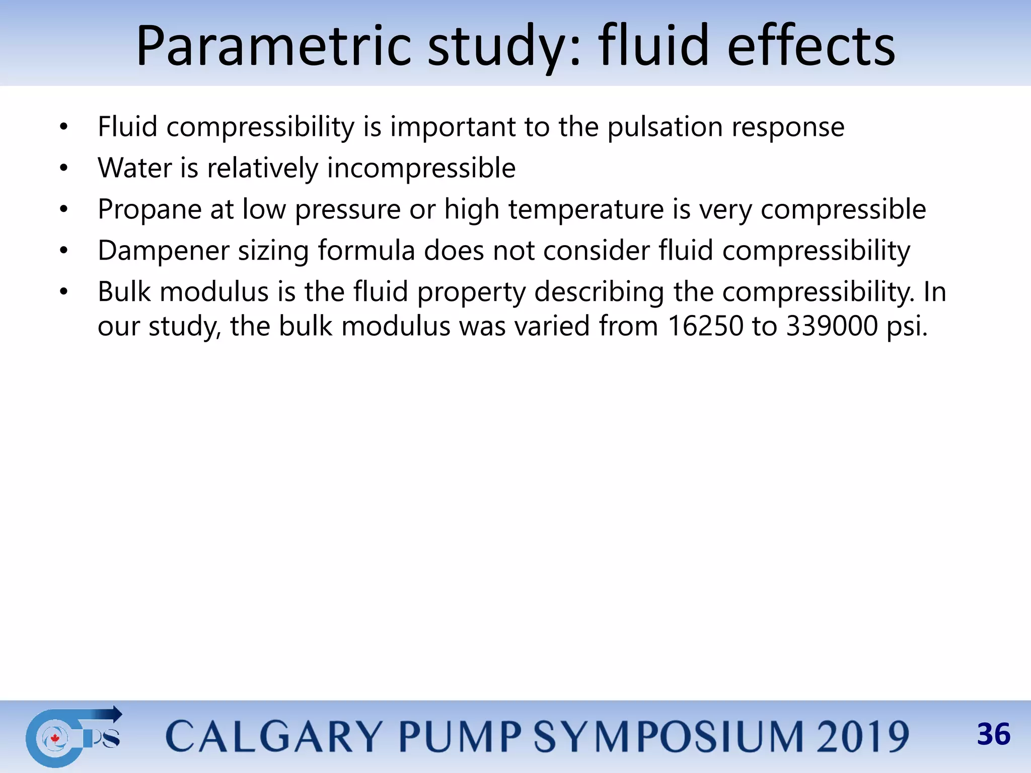


This document summarizes a parametric study evaluating design parameters for pulsation dampeners on plunger pumps. The study uses a pulsation model to examine the effects of: 1) Pump system configuration, finding that complex piping can significantly impact pulsations compared to just the pump package. 2) Dampener location, finding pulsations generally increase as the dampener moves farther from the pump, and are still high when located next to the pump due to quarter-wave resonances. 3) Dampener neck geometry, finding pulsations decrease with a larger neck diameter and shorter neck length to maximize the dampener's effect. The study also examines the impacts of fluid compressibility and