Downloaded 105 times
![P
ressure relief systems are vital
in the chemical process indus-
tries (CPI) for handling a wide
variety of situations. They are
used to prevent pressurization above
a system’s design pressure; for vent-
ing during an unusual or emergency
situation; and for normal depressur-
ization during a shutdown, as exam-
ples. In some cases, such as when non-
combustible gases including steam,
air and nitrogen are used, venting into
the atmosphere may be an option. In
other cases, such as those typically en-
countered in the hydrocarbon sector,
elaborate systems for the disposal of
vented gases may be required.
This article describes some of the
causes of overpressurization, the
types of valves and rupture disks
that are available and some of the
components needed for a pressure
relief system. Example calculations
are given, as well as a list of instal-
lation considerations.
Causes of overpressurization
An overpressurization may result
from a single cause or a combination
of events. Typically, not all causes
will occur simultaneously. In case of
an external fire in vessels that pre-
dominantly handle vapors, such as
knockout drums, there may be a rapid
temperature rise in the metal accom-
panied with a rise in pressure due
to expansion. In case of external fire
in vessels that contain liquids, there
will be a rise in pressure as the liq-
uid vaporizes. Pressure may also
rise abruptly due to thermal expan-
sion when a blocked-in pipeline or
other equipment containing a liquid
is heated. Relieving pressure under
these situations is essential to prevent
failure. It is also required in systems
where a continuous flow of vapor or
liquid is suddenly stopped by a down-
stream blockage.
While a full description of the vari-
ous causes of overpressurization is be-
yond the scope of this article, details
are provided by API [1]. The following
is a partial list:
• Blocked outlet
• Failure of control valve
• Cooling water failure
• Power failure
• Instrument air failure
• Heat-exchanger-tube failure
• External fire
Safety relief valves
There are several types of safety re-
lief valves available on the market,
including the following.
Conventional: Conventional pres-
sure-relief valves are susceptible to
back pressure. Such valves are not
recommended when the total back
pressure exceeds 10% of the set pres-
sure. For systems operating at pres-
sures close to atmospheric or at low
pressures, the limit of 10% is rarely
achieved. Therefore, these valves find
application mainly in high-pressure
systems, or in systems that relieve to
the atmosphere (for example, steam
and air).
Balanced bellows: Balanced pres-
sure-relief valves are used when con-
ventional pressure-relief valves can-
not be used because of the reasons
mentioned above. Such valves are
not susceptible to back pressures as
high as 50% of set pressure. The valve
opening is independent of the back
pressure. At higher back pressures,
these valves will still relieve at the set
point, but with a reduction in capac-
ity. Therefore, it is recommended that
if balanced pressure-relief valves are
to perform as rated, the back pressure
should be limited to about 50% of the
set pressure.
Pilot operated: In such valves, the
main pressure-relief valve opens
through a pilot valve. Pilot operated
valves are used in the following cir-
cumstances: 1) The pressure-relief-
valve set pressure is lower than 110%
of the operating pressure and 2) when
high back pressures are applicable.
The opening of the valve is indepen-
dent of back pressure.
Rupture disks
A rupture disk is a pressure reliev-
ing device that is used for the same
purpose as a relief valve, but a disk is
a non-reclosing device — or in other
words, once it is open it will not close.
This means that whatever is in the
system will continue to vent until
stopped by some form of intervention.
The following are the applications of
rupture disks [3]:
For quick action: Rupture disks
are very fast acting. Therefore, they
are used in cases where relief valves
may not be fast enough to prevent a
catastrophic failure. Some engineers
prefer to use rupture disks to prevent
heat-exchanger-tube ruptures because
they are concerned that pressure relief
valves would be too slow to prevent
pressure build-up scenarios.
To prevent plugging of relief
valves: In certain processes, the pro-
cess fluid contains solid particles that
may cause blockage within a relief
valve, rendering it useless. In such
cases, a rupture disk is normally used
upstream of the relief valve. Purified
terephthallic acid plants (PTA) is a
typical application example.
Handling highly viscous liquids:
In systems handling highly viscous
liquids, such as polymers, depressur-
ization through a relief valve may be
too slow for a given situation. A rup-
Feature Report
40 Chemical Engineering www.che.com November 2008
Feature Report
Siddhartha Mukherjee
Lurgi India Company Ltd.
Pressure-Relief
System Design
Unexpectedhigh-
pressuresituationscan
berelievedwithaproper
relief-systemdesign](https://image.slidesharecdn.com/pressurereliefsystemdesign-151209065558-lva1-app6891/75/Pressure-relief-system_design-1-2048.jpg)
![ture disk is the preferred choice.
Loss prevention: In systems han-
dling low-molecular-weight hydrocar-
bons, there is always a chance that
some material will pass through the
pressure relief valve into the flare
system — leading to material loss. In
such cases, a rupture disk is normally
used upstream of the relief valve.
For economic reasons: Many pro-
cess industries use exotic materials,
such as titanium and Hastelloy C.
In these cases, rather than having
a pressure relief valve made of Has-
telloy C, it may be cheaper to have a
rupture disk made of Hastelloy C fol-
lowed by a stainless-steel pressure-
relief valve.
Pressure relief systems
Open and closed systems
In cases where non-hazardous fluids
are used, such as steam, water and air,
a typical pressure-relief system con-
sists of several pressure relief valves
that discharge through short tail pipes
to the atmosphere. These systems are
termed open disposal systems.
When hazardous fluids, such as hy-
drocarbons are in use, the tail pipes
are connected to a common flare
header, which is ultimately routed to
a flare stack where the hydrocarbons
are burned. In many cases, the fluid
relieved is toxic or flammable. In such
cases, it is mandatory to discharge
the gases through a closed disposal
system such as the flare. The flare
system converts the flammable va-
pors to less objectionable compounds
by combustion.
Components of closed systems
Pressure-relief valve-outlet pip-
ing: The flare system starts with out-
let pipes from the various pressure re-
lief valves of a unit. These valves are
piped together to a common unit-flare
header, which is routed to the unit-
flare knockout (K.O.) drum.
Unit flare header: Discharge pipes
from the pressure relief valves in in-
dividual units are connected to the
respective unit-flare headers. These
headers are either connected directly
to the main flare header, or are routed
to the flare K.O. drums, which in turn
are connected to the main flare header
(Figure 1) with a recommended mini-
mum slope of 1:500. All unit flare
headers are continuously purged from
the upstream end towards the respec-
tive K.O. drums to avoid ingress of
air into the system. Fuel gas, or inert
gases, such as nitrogen are typically
used as purge gas.
Unit-flare knockout drum: In cases
where the discharge from a unit is ex-
pected to contain appreciable quanti-
ties of liquids, especially corrosive,
fouling and congealing liquids, a unit-
flare K.O. drum of a suitable size is
mandatory. Another reason for requir-
ing such a drum may be that it is not
feasible to have all headers continu-
ously slope toward the main-flare K.O.
drum. In this case, the unit flare head-
ers are sloped toward the unit-flare
K.O. drums. The vapors from these
drums are then routed to the main
flare header [2].
Unit-flare K.O. drums are sized
to separate particles in the range
of 300–600 microns, and hold liquid
discharge for 5–10 min from a single
source. The liquid collected in these
drums should preferably be drained
by gravity to the blowdown drum. If
a congealing type of liquid is likely to
be discharged, the drums should be
heat traced or provided with steam
coils [2].
Main flare header: The main flare
header receives discharge through in-
dividual unit-flare headers, or through
unit-flare K.O.drums.The flare header
should not have pockets and should be
free draining toward the nearest K.O.
drum, typically with a slope of 1:500.
Although flare headers are nor-
mally sized based on pressure drop,
Chemical Engineering www.che.com November 2008 41
01-PSV-01
01-PSV-02
01-PSV-03
01-PSV-04
01-PSV-05
Unit 01
02-PSV-01
02-PSV-02
02-PSV-03
02-PSV-04
02-PSV-05
Unit 02
03-PSV-01
03-PSV-02
03-PSV-03
03-PSV-04
03-PSV-05
Unit 03
Unit flare
K.O. drum
Unit flare
K.O. drum
Unit flare
K.O. drum
Main flare
K.O. drum
Main flare header
Flare stack
Battery limit
(unit 01)
Battery limit
(unit 02)
Battery limit
(unit 03)
FIGURE 1. A network of flare head-
ers may be used in a complex process
Definition of Terms
Set pressure: The inlet gauge pressure at which the pressure relief valve is set to open
under service condition
Overpressure: The pressure increase over the set pressure of the relieving device ex-
pressed as a percentage
Relieving pressure: The sum of the valve set pressure and the overpressure
Superimposed back pressure: The static pressure that exists at the outlet of a pressure
relief device at the time the device is required to operate. It is the result of the pressure in
the discharge system coming from other sources and may be constant or variable
Built-up back pressure: The increase in pressure in the discharge header that develops
as a result of flow after the pressure relief device opens
Back pressure: The pressure that develops at the outlet of a pressure relief device after
the pressure relief device opens. It is the sum of the superimposed and the built-up back
pressures
Abbreviations
P1 Pressure at pipe inlet, kg/cm2a
P2 Pressure at pipe outlet, kg/cm2a
W Gas flowrate, kg/h
Z Gas compressibility factor
T Gas temperature, K
Mw Gas molecular weight, kg/kmol
f Moody’s friction factor
k Ratio of specific heats, Cp/Cv
a Absolute pressure, as in kg/cm2a
g Gauge pressure, as in kg/cm2g](https://image.slidesharecdn.com/pressurereliefsystemdesign-151209065558-lva1-app6891/75/Pressure-relief-system_design-2-2048.jpg)
![velocity cannot be ignored. A Mach
number in the range of 0.2–0.5 is
recommended. The third criterion
that should be checked is the change
in density of flare gases along the
length of the flare header. In many
cases where flare discharges are at
high temperatures, the flare gases
cool down due to the length of the
flare header. This leads to an increase
in density and, correspondingly, a de-
crease in flowrates. Therefore, while
estimating pressure drops in such
flare lines, it is a good idea to divide
the header into sections and estimate
pressure drops separately.
Main-flare knockout drum: In ad-
dition to the unit-flare K.O. drum, a
main-flare K.O. drum close to the flare
stack should be provided. This takes
care of condensation in the header
that results from atmospheric cooling.
Similar to the unit-flare K.O. drums,
these drums are also sized to separate
out liquid droplets of 300–600 microns
in size, and for holdup of 20–30 min [1]
of liquid release. Pumps are installed
with the K.O. drum to transport any
collected liquid to a safe location. The
pumping capacity should allow the
liquid holdup to be emptied in 15–20
min. When congealing liquids are in
use, the drums should be provided
with steam coils [2].
Seal drum: Seal drums are located
close to the flare stack or are sometimes
integral with the flare stack. These
drums protect against flame flash-
back from the flare tip. The seal drum
should have a diameter of at least two
times the flare pipe diameter [1].
Flare stack: Flare stacks are usually
elevated structures designed to burn
flammable vapors.
Relief system piping
Inlet piping: The inlet piping from
the protected equipment to the pres-
sure relief valve should be sized to
prevent excessive pressure loss that
can cause chattering with consequent
reduction in flow and damage to seat-
ing surfaces. The recommended prac-
tice is to limit the total pressure drop
in the inlet piping to 3% of the safety-
valve set pressure [1]. The piping is
designed to drain towards the pro-
tected vessel.
Discharge piping: In case of over-
pressurization in a vessel, the rel-
evant pressure-relief valve will start
to open at the set pressure. At this
moment, the downstream pressure at
the valve is the superimposed back
pressure of the system. The valve
keeps opening as the pressure builds
up. The resultant flow creates a built-
up back pressure on the discharge
pipe. As long as the built-up back
pressure is less than the overpres-
sure after the valve opens, the valve
will remain open and perform satis-
factorily. If however, the built-up back
pressure develops at a rate greater
than the overpressure, it will tend to
close the valve. Therefore, proper siz-
ing of discharge pipes is very impor-
tant in such systems.
Discharge piping and manifolds
are sized for the contingency that
produces the largest relief load. Pipe
sizing is carried out by working back-
ward from the battery limit of the
unit flare header up to the outlet of
individual, pressure safety valves.
The superimposed back pressure of
the flare header at the battery limit
is defined. Thereafter, based on the
relief loads, pressure drop calcula-
tions are carried out to arrive at the
back pressure of the individual, pres-
sure relief valves. In the course of
the calculations, two parameters are
checked for compliance:
• The Mach number at each pipe sec-
tion should not exceed 0.5
• The back pressure at each safety
valve should not exceed 30–50% of
the set pressure
The isothermal flow equation based
on the outlet Mach number is given by
API [1]. This method calculates pres-
sure buildup backward up to the out-
let of relief valves, thus avoiding the
need for trial and error methods:
(1a)
or,
Feature Report
42 Chemical Engineering www.che.com November 2008
95,648 kg/h69,356 kg/h28,012 kg/h
Unit flare
header
Mainflare
header
To main flare
K.O. drum
12,870kg/h
13,422kg/h
10,536kg/h
14,076kg/h
12,960kg/h15,052kg/h
16,732kg/h
ABCD
PSV-06
PSV-05
PSV-04
PSV-03
PSV-02
PSV-01
PSV-07
PSV-08
PSV-09
PSV-10
PSV-11
PSV-12
FIGURE 2. This sketch of a typical flare system is used as the basis for the sample
calculations explained in the given example
Table 1. Relief Load Summary
Relief Valve
Tag No.
Relief load, kg/h
Cooling
water failure
External
fire
PSV-01 12,870 13,453
PSV-02 6,750
PSV-03 10,536 9,872
PSV-04 14,076 8,970
PSV-05 5,783
PSV-06 12,960 11,423
PSV-07 15,052 6,432
PSV-08 5,764
PSV-09 16,732 8,976
PSV-10 7,432
PSV-11 13,422 5,133
PSV-12 9,984
Total load 95,648](https://image.slidesharecdn.com/pressurereliefsystemdesign-151209065558-lva1-app6891/75/Pressure-relief-system_design-3-2048.jpg)
![(1b)
The Mach number at the outlet of
each pipe section is given as follows
[1]:
(2)
In the next section, a solved example
illustrates the procedure.
Example
An extractive distillation plant has
twelve safety valves. There are two
major relief scenarios: cooling water
failure and external fire. Table 1 sum-
marizes the relief rates under these
two conditions. The governing case is
the cooling water failure because it
occurs plant wide. External fire oc-
curs only at localized areas and the
relief loads come from only a couple
of safety valves. Hence, we will con-
sider the cooling water failure case
here. For simplicity, we will assume
that set pressures of all safety valves
are 5.0 kg/cm2 g.
The flare network is divided into
segments as shown in Figure 2. Seg-
ment 1 is a section of the flare header
between the battery limit A and point
B. Likewise, segment 2 is a section of
the flare header between points B and
C. Let us assume a superimposed back
pressure at point A of 1.5 kg/cm2 a.
Piping between points A and B
Data
Flowrate: 95,648 kg/h (Table 1)
Pressure at point A, P2: 1.5 kg/cm2a
Molecular weight of vapor, Mw: 86
Temperature of vapor: 100°C
Straight length of pipe : 15 m
Number of elbows: 0
Number of valves: 1
Number of tees: 0
Compressibility factor: 0.95
Ratio of specific heats, Cp/Cv: 1.4
Viscosity: 0.000009 kg/m s
Roughness factor, ε:
0.0001m (0.1 mm)
Pipe diameter, D (assumed):
0.30 m (12 in.)
Calculations
Density of vapor: PMw/ZRT
= 4.2899 kg/m3
Volumetric flowrate:
95,648/(4.2899 x 3,600) = 6.193 m3/s
Velocity in pipe: 6.193 x 4/(π x (0.30)2)
= 87.61 m/s
Reynolds number, NRe:
0.30 x 87.61 x 4.2899/0.000009
= 12,528,371
Outlet Mach Number, M2:
3.293 x 10⁻⁷ (95,648/(1.5 x 0.302)) x
(0.95 x 373/1.4 x 86)0.5 = 0.4003
Fanning’s friction factor (to be solved
by iteration):
1/√f = –4log[ε/(3.7D) + 1.256/(NRe√f)]
= 0.0038
Moody’s friction factor: 4 x 0.0038
= 0.0152
Equivalent length: 17.8 m
fL/D: 0.0152 x 17.8/0.3
Using Equation (1b), P1/P2 is calcu-
lated to be: 1.08226
P1: 1.08226 x 1.5
= 1.6234 kg/cm2a
Hence, the pressure at point B is
1.6234 kg/cm2a
Piping between point B and
PSV-01, 1st trial
Data
Set pressure of PSV-01: 5.0 kg/cm2g
Flowrate: 12,870 kg/h (Table 1)
Pressure at point B, P2:
1.6234 kg/cm2a
Molecular weight of vapor Mw: 86
Temperature of vapor: 100°C
Straight length of pipe: 30 m
Number of elbows: 3
Number of valves: 1
Number of tees: 0
Compressibility factor: 0.95
Ratio of specific heats, Cp/Cv: 1.4
Viscosity: 0.000009 kg/m s
Chemical Engineering www.che.com November 2008 43
Table 2. Flare Discharge Piping Calculations
Segment Set
pres-
sure
Line
size
Line
size
Flow-
rate
Pres-
sure
P2
Den-
sity
Rough-
ness
factor
Pipe
length
No. of
tees
No. of
valves
No. of
elbows
Pres-
sure
P1
Pres-
sure
P1
% of
set
pres-
sure
Mach
no.
kg/
cm2g
m in. kg/h kg/
cm2a
kg/m3 mm m kg/
cm2a
kg/
cm2g
A to B 0.30 12 95,648 1.5000 4.2899 0.1 15 0 1 0 1.6234 0.5904 0.4004
B to PSV-01 5.0 0.10 4 12,870 1.6234 4.6428 0.1 30 0 1 3 2.7780 1.745 34.9 0.4480
B to PSV-11 5.0 0.15 6 13,422 1.6234 4.6428 0.1 30 0 1 3 1.8282 0.7952 15.9 0.2077
B to C 0.25 10 69,356 1.6234 4.6428 0.1 15 0 0 0 1.7528 0.7198 0.3863
C to PSV-03 5.0 0.15 6 10,536 1.7528 5.0129 0.1 30 0 1 3 1.8712 0.8382 16.8 0.1510
C to PSV-04 5.0 0.15 6 14,076 1.7528 5.0129 0.1 30 0 1 3 1.9616 0.9286 18.6 0.2017
C to PSV-09 5.0 0.15 6 16,732 1.7528 5.0129 0.1 30 0 1 3 2.0449 1.0119 20.2 0.2398
C to D 0.20 8 28,012 1.7528 5.0129 0.1 15 0 0 0 1.8111 0.7781 0.2258
D to PSV-06 5.0 0.15 6 12,960 1.8111 5.1796 0.1 30 0 1 3 1.9832 0.9502 19.0 0.1797
D to PSV-07 5.0 0.15 6 15,052 1.8111 5.1796 0.1 30 0 1 3 2.0417 1.0087 20.2 0.2088](https://image.slidesharecdn.com/pressurereliefsystemdesign-151209065558-lva1-app6891/75/Pressure-relief-system_design-4-2048.jpg)
![Feature Report
44 Chemical Engineering www.che.com November 2008
Roughness factor, ε:
0.0001m (0.1 mm)
Pipe diameter, D (assumed):
0.08 m (3 in.)
Calculations
(detailed steps not repeated)
Density of vapor: 4.6428 kg/m3
Volumetric flowrate: 0.7700 m/s
Velocity in pipe: 153.186 m/s
Reynolds number, NRe: 6,321,901
Outlet Mach number: 0.6998
Fanning’s friction factor: 0.0052
Moody’s friction factor: 0.0208
Equivalent length: 40.65 m
P1/P2: 2.67214
P1: 4.3380 kg/cm2a
Hence, the back pressure at PSV-01 is
4.3380 kg/cm2a, or 3.3050 kg/cm2g.
The ratio of the back pressure to
the set pressure for PSV-01 works out
to 66.10% which is more than that
recommend for balanced bellow-type
valves. In addition, the Mach number
is 0.6998, which is greater than the
recommended limit of 0.5. Therefore,
we need to increase the line size in the
stretch between B and PSV-01. Let us
now select a line size of 4 in. for the
second trial.
Piping between point B and
PSV-01, 2nd trial
Data
Set pressure of PSV-01: 5.0 kg/cm2g
Flowrate: 12,870 kg/h
Pressure at point B, P2:
1.6234 kg/cm2a
Molecular weight of vapor, Mw: 86
Temperature of vapor: 100°C
Straight length of pipe: 30 m
Number of elbows: 3
Number of valves: 1
Number of tees: 0
Compressibility factor: 0.95
Ratio of specific heats, Cp/Cv: 1.4
Viscosity: 0.000009 kg/m s
Roughness factor, ε:
0.0001m (0.1 mm)
Pipe diameter, D (assumed):
0.10 m (4 in.)
Calculations
(detailed steps not repeated)
Density of vapor: 4.6428 kg/m3
Volumetric flowrate: 0.7700 m/s
Velocity in pipe: 98.03 m/s
Reynolds number, NRe: 5,057,041
Outlet Mach Number: 0.4480
Fanning’s friction factor: 0.0049
Moody’s friction factor: 0.0196
Equivalent length: 43.31 m
P1/P2: 1.71121
P1: 2.7780 kg/cm2a
Hence, the back pressure at PSV-01 is
2.7780 kg/cm2a, or 1.745 kg/cm2g.
The ratio of the back pressure to
the set pressure for PSV-01 is 34.90%,
which is acceptable. The Mach num-
ber is 0.4480, which is also within ac-
ceptable limits.
A summary of parameters and cal-
culation results is given in Table 2.
Installation features
Correct installation of relief valves
and the associated relief system is
very important for their proper opera-
tion during upsets to ensure the safety
of personnel and the plant. Some use-
ful guidelines follow:
• Pressure relief valves should be
connected to the vapor space of the
protected equipment
• The inlet line should be self drain-
ing back to the process vessel. This
is to prevent accumulation of liquid
that can corrode or block the sys-
tem. Likewise, the outlet line from
the pressure relief valve should be
self-draining to the flare header. To
meet this requirement, it is recom-
mended that relief valves are in-
stalled at a high point in the sys-
tem (Figure 3)
• For reliable overpressure protection
it is best to install pressure relief
valves without any isolation valves.
However, pressure relief valves
sometimes do not reseat properly
and start to leak. Therefore, in many
cases, two safety valves are installed
to allow replacement of relief valves
that are leaking while the plant is
in operation. This also facilitates
testing and servicing of relief valves
regularly without interrupting plant
operations
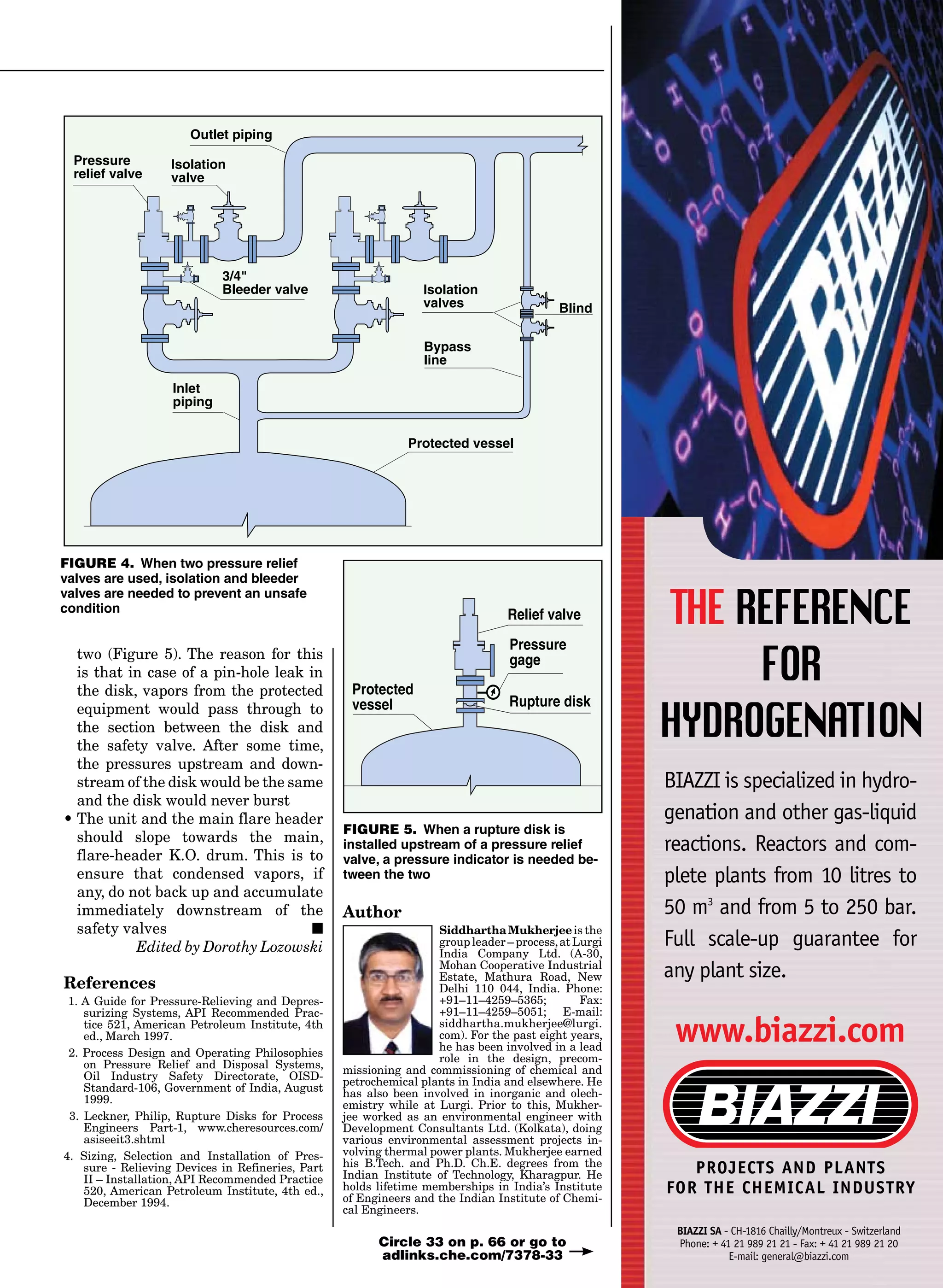
• Whenever two pressure relief valves
are installed as mentioned above,
isolation valves are provided for each
relief valve (Figure 4). This is to fa-
cilitate isolation of the “A” valve for
maintenance while taking valve “B”
online when required. In such cases, a
¾-in. bleeder valve with an isolation
valve is recommended in between the
isolation valve and the pressure relief
valve. This is needed because when
the “A” valve has been isolated, the
section between the isolation valve
and the pressure relief valve is still
at the operating pressure of the col-
umn. The bleeder is used to depres-
surize this section before the valve
is removed from the line, otherwise
it could be an unsafe condition for
maintenance personnel [4]
• Whenever two pressure relief
valves are provided, it is mandatory
that a mechanical interlock system
is installed between the respective
isolation valves to ensure that one
of the isolation valves is open at all
times. This is to eliminate opera-
tor error, which might mistakenly
create a situation where both the
isolation valves are in the closed
position, leading to unavailability
of either of the relief valves for any
particular equipment
• Pressure relief valves in steam,
water or air service are connected
to the atmosphere through a short
vertical pipe. To keep this pipe free
from liquid accumulation, a small
weep hole is drilled at the lowest
point of this pipe
• Whenever a rupture disk is installed
upstream of a pressure relief valve,
it is important to have a pressure
indicator in the section between the
Column
Safety
valve
outlet line
Safety valve
Column
outlet line
FIGURE 3. In order to make relief
valves self-draining to the flare header,
it is recommended that they be in-
stalled at a high point in the system](https://image.slidesharecdn.com/pressurereliefsystemdesign-151209065558-lva1-app6891/75/Pressure-relief-system_design-5-2048.jpg)

This document discusses pressure relief systems, which are critical in the chemical process industries to safely handle overpressurization. It describes causes of overpressurization, types of safety valves and rupture disks used for relief, and components of open and closed pressure relief systems. Open systems vent non-hazardous gases to the atmosphere, while closed systems route flammable gases through flare headers and knockout drums to be burned in a flare stack. The document provides example calculations for sizing relief valves, piping, and other components to ensure systems can safely relieve pressure without resealing valves.


