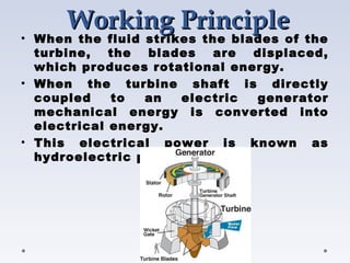
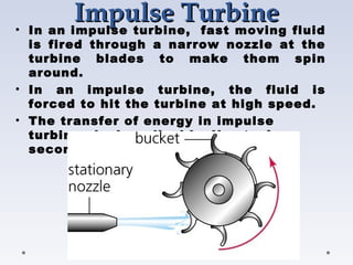
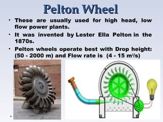
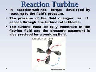
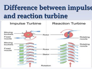
Hydraulic
Hydraulic
TURBINE
TURBINE
S
S
By :
Akshay Dagadu
Jadhav
What is a
What is a TURBINE
TURBINE???
???
 A turbine is a rotary mechanical device that
extracts energy from a  fast moving flow of
water, steam, gas, air, or other fluid and
converts it into useful work.
 A turbine is a turbo-machine with at least
one moving part called a rotor assembly,
which is a shaft or drum with blades
attached.
 Moving fluid acts on the blades so that they
move and impart rotational energy to the
rotor. 
Basic types of TURBINES
• Water Turbine 
• Steam Turbine
• Gas Turbine
• Wind Turbine
Although the same principles apply to all turbines,
their specific designs differ sufficiently to merit
separate descriptions.
Working
Working Principle
Principle
• When the fluid strikes the blades of the
turbine, the blades are displaced,
which produces rotational energy.
• When the turbine shaft is directly
coupled to an electric generator
mechanical energy is converted into
electrical energy.
• This electrical power is known as
hydroelectric power.
Types of Water Turbines
• Impulse turbines
• Reaction turbines
Impulse Turbine
Impulse Turbine
• In an impulse turbine,  fast moving fluid
is fired through a narrow nozzle at the
turbine blades to make them spin
around.
• In an impulse turbine, the fluid is
forced to hit the turbine at high speed.
• The transfer of energy in impulse
turbines is described by Newton’s
second law of motion.
Types of Impulse Turbines
I. Pelton Turbine
II. Cross-flow Turbine
Pelton Wheel
Pelton Wheel
• These are usually used for high head, low
flow power plants.
• It was invented by Lester Ella Pelton in the
1870s.
• Pelton wheels operate best with Drop height:
(50 - 2000 m) and Flow rate is  (4 - 15 m3
/s)
Applications
Applications
• Pelton wheels are the preferred when the
available water source has relatively
high hydraulic head at low flow rates.
• Mostly used Pico hydro electric power
generation unit.
• Pelton wheels are made in all sizes.
• For maximum power and efficiency, the wheel
and turbine system is designed such that the
water jet velocity is twice the velocity of the
rotating buckets.
Cross-flow
Cross-flow Turbine
Turbine
• It is developed by Anthony Michel, in 1903
and is used for low heads. (10–70 meters)
•  As with a water wheel, the water is admitted
at the turbine's edge. After passing the
runner, it leaves on the opposite side.
• The cross-flow turbine is a low-speed
machine that is well suited for locations with
a low head but high flow.
Applications
Applications
• The peak efficiency of a cross-flow turbine is
somewhat less than a kaplon, francis or
pelton turbine.
• It has a low price, and good regulation.
• As water going through the runner twice,
provides additional efficiency.
• Cross-flow turbines are mostly used in mini
and micro hydropower units. 
• Its good point as When the water leaves the
runner, it also helps clean the runner of small
debris and pollution.
Reaction
Reaction Turbine
Turbine
• In reaction turbines torque developed  by
reacting to the fluid's pressure.
• The pressure of the fluid changes as it
passes through the turbine rotor blades.
• The turbine must be fully immersed in the
flowing fluid and the pressure casement is
also provided for a working fluid.
Difference between impulse
and reaction turbine
Types of Reaction Turbines
• Kaplan Turbine
• Francis Turbine
• Kinetic Turbine
Kaplan Turbine
Kaplan Turbine
• The Kaplan turbine is a water
turbine which has adjustable blades
and is used for low heads and high
discharges.
• It was developed in 1913 by the
Austrian professor Viktor Kaplan.
• The Kaplan turbine is an inward
flow reaction turbine, which means that
the working fluid changes pressure as
it moves through the turbine and gives
up its energy.
• Water is directed tangentially through
the wicket gate and spirals on to a
propeller shaped runner, causing it to
spin.
Kaplan Turbine
Kaplan Turbine
Applications
Applications
• Kaplan turbines are widely used throughout
the world for electrical power production.
They cover the lowest head hydro sites and
are especially suited for high flow conditions.
• Inexpensive micro turbines on the Kaplan
turbine model are manufactured for individual
power production with as little head.
• Large Kaplan turbines are individually
designed for each site to operate at the
highest possible efficiency, typically over
90%. They are very expensive to design,
manufacture and install, but operate for
decades.
Francis Turbine
Francis Turbine
• The Francis turbine is a type of water turbine that
was developed by James B.Franceis and are used
for medium head (45-400m) and medium
discharge (10-700 m3
/s).
• The Francis turbine is a type of reaction turbine, a
category of turbine in which the working fluid
comes to the turbine under immense pressure and
the energy is extracted by the turbine blades from
the working fluid.
• The turbine's exit tube is shaped to help
decelerate the water flow and recover the
pressure.
• Water flow is radial from exterior to interior.
Francis Turbine
Francis Turbine
Applications
Applications
• Francis type units cover a head range from 40
to 600 m (130 to 2,000 ft).
• Its efficiency decreases as flow decreases.
• They may also be used for pumped storage,
where a reservoir is filled by the turbine (acting
as a pump) driven by the generator acting as a
large electrical motor during periods of low
power demand.
Kinetic Turbines
Kinetic Turbines
• Kinetic energy turbines, also called free-
flow turbines, generate electricity from the
kinetic energy present in flowing water.
• The systems may operate in rivers, man-
made channels, tidal waters, or ocean
currents.
• Kinetic systems utilize the water stream's
natural pathway.
• They do not require the diversion of water
through manmade channels, riverbeds, or
pipes,
• They might have applications in such
conduits.
• Kinetic systems do not require large civil
works; however, they can use existing
structures such as bridges, tailraces and
channels and do not require any dam or
Kinetic Turbines
Kinetic Turbines
STATION Region STATE
CAPACITY
(MW)
TURBINE
Koyna Western Maharashtra 1,960
Pelton (stage I & II)
Francis (Stage III &
Stage IV)
Srisailam
Dam
Southern
Andhra
Pradesh,
Telangana
1,670 Francis
Sharavathi Southern Karnataka 1608 Francis
Nathpa
Jhakri
Northern
Himachal
Pradesh
1500 Francis
Sardar
Sarovar
Western Gujarat 1450 Francis
Bhakra Dam Northern Punjab 1325 Francis
Mulshi Dam Western Maharashtra 300 Pelton
Turbine used in Hydroelectric Power Generation Unit
References
References
• Mechanical engineering department manuals Bhagwant
universty ajmer .
• Fluid mechanics with engineering applicatations 10 edition
by E.John Finnemore and Joesph B. Franzini
• Hydraulics and Fluid mechanics by E.H.Lewitt 10th
edition
Hydraulic Turbines.pdf

Hydraulic Turbines.pdf

  • 1.
  • 2.
    What is a Whatis a TURBINE TURBINE??? ???  A turbine is a rotary mechanical device that extracts energy from a  fast moving flow of water, steam, gas, air, or other fluid and converts it into useful work.  A turbine is a turbo-machine with at least one moving part called a rotor assembly, which is a shaft or drum with blades attached.  Moving fluid acts on the blades so that they move and impart rotational energy to the rotor. 
  • 3.
    Basic types ofTURBINES Basic types of TURBINES • Water Turbine  • Steam Turbine • Gas Turbine • Wind Turbine Although the same principles apply to all turbines, their specific designs differ sufficiently to merit separate descriptions.
  • 4.
    Working Working Principle Principle • Whenthe fluid strikes the blades of the turbine, the blades are displaced, which produces rotational energy. • When the turbine shaft is directly coupled to an electric generator mechanical energy is converted into electrical energy. • This electrical power is known as hydroelectric power.
  • 5.
    Types of WaterTurbines Types of Water Turbines • Impulse turbines • Reaction turbines
  • 6.
    Impulse Turbine Impulse Turbine •In an impulse turbine,  fast moving fluid is fired through a narrow nozzle at the turbine blades to make them spin around. • In an impulse turbine, the fluid is forced to hit the turbine at high speed. • The transfer of energy in impulse turbines is described by Newton’s second law of motion.
  • 7.
    Types of ImpulseTurbines Types of Impulse Turbines I. Pelton Turbine II. Cross-flow Turbine
  • 8.
    Pelton Wheel Pelton Wheel •These are usually used for high head, low flow power plants. • It was invented by Lester Ella Pelton in the 1870s. • Pelton wheels operate best with Drop height: (50 - 2000 m) and Flow rate is  (4 - 15 m3 /s)
  • 9.
    Applications Applications • Pelton wheelsare the preferred when the available water source has relatively high hydraulic head at low flow rates. • Mostly used Pico hydro electric power generation unit. • Pelton wheels are made in all sizes. • For maximum power and efficiency, the wheel and turbine system is designed such that the water jet velocity is twice the velocity of the rotating buckets.
  • 10.
    Cross-flow Cross-flow Turbine Turbine • Itis developed by Anthony Michel, in 1903 and is used for low heads. (10–70 meters) •  As with a water wheel, the water is admitted at the turbine's edge. After passing the runner, it leaves on the opposite side. • The cross-flow turbine is a low-speed machine that is well suited for locations with a low head but high flow.
  • 11.
    Applications Applications • The peakefficiency of a cross-flow turbine is somewhat less than a kaplon, francis or pelton turbine. • It has a low price, and good regulation. • As water going through the runner twice, provides additional efficiency. • Cross-flow turbines are mostly used in mini and micro hydropower units.  • Its good point as When the water leaves the runner, it also helps clean the runner of small debris and pollution.
  • 12.
    Reaction Reaction Turbine Turbine • Inreaction turbines torque developed  by reacting to the fluid's pressure. • The pressure of the fluid changes as it passes through the turbine rotor blades. • The turbine must be fully immersed in the flowing fluid and the pressure casement is also provided for a working fluid.
  • 13.
    Difference between impulse Differencebetween impulse and reaction turbine and reaction turbine
  • 14.
    Types of ReactionTurbines Types of Reaction Turbines • Kaplan Turbine • Francis Turbine • Kinetic Turbine
  • 15.
    Kaplan Turbine Kaplan Turbine •The Kaplan turbine is a water turbine which has adjustable blades and is used for low heads and high discharges. • It was developed in 1913 by the Austrian professor Viktor Kaplan. • The Kaplan turbine is an inward flow reaction turbine, which means that the working fluid changes pressure as it moves through the turbine and gives up its energy. • Water is directed tangentially through the wicket gate and spirals on to a propeller shaped runner, causing it to spin.
  • 16.
  • 17.
    Applications Applications • Kaplan turbinesare widely used throughout the world for electrical power production. They cover the lowest head hydro sites and are especially suited for high flow conditions. • Inexpensive micro turbines on the Kaplan turbine model are manufactured for individual power production with as little head. • Large Kaplan turbines are individually designed for each site to operate at the highest possible efficiency, typically over 90%. They are very expensive to design, manufacture and install, but operate for decades.
  • 18.
    Francis Turbine Francis Turbine •The Francis turbine is a type of water turbine that was developed by James B.Franceis and are used for medium head (45-400m) and medium discharge (10-700 m3 /s). • The Francis turbine is a type of reaction turbine, a category of turbine in which the working fluid comes to the turbine under immense pressure and the energy is extracted by the turbine blades from the working fluid. • The turbine's exit tube is shaped to help decelerate the water flow and recover the pressure. • Water flow is radial from exterior to interior.
  • 19.
  • 20.
    Applications Applications • Francis typeunits cover a head range from 40 to 600 m (130 to 2,000 ft). • Its efficiency decreases as flow decreases. • They may also be used for pumped storage, where a reservoir is filled by the turbine (acting as a pump) driven by the generator acting as a large electrical motor during periods of low power demand.
  • 21.
    Kinetic Turbines Kinetic Turbines •Kinetic energy turbines, also called free- flow turbines, generate electricity from the kinetic energy present in flowing water. • The systems may operate in rivers, man- made channels, tidal waters, or ocean currents. • Kinetic systems utilize the water stream's natural pathway. • They do not require the diversion of water through manmade channels, riverbeds, or pipes, • They might have applications in such conduits. • Kinetic systems do not require large civil works; however, they can use existing structures such as bridges, tailraces and channels and do not require any dam or
  • 22.
  • 23.
    STATION Region STATE CAPACITY (MW) TURBINE KoynaWestern Maharashtra 1,960 Pelton (stage I & II) Francis (Stage III & Stage IV) Srisailam Dam Southern Andhra Pradesh, Telangana 1,670 Francis Sharavathi Southern Karnataka 1608 Francis Nathpa Jhakri Northern Himachal Pradesh 1500 Francis Sardar Sarovar Western Gujarat 1450 Francis Bhakra Dam Northern Punjab 1325 Francis Mulshi Dam Western Maharashtra 300 Pelton Turbine used in Hydroelectric Power Generation Unit Turbine used in Hydroelectric Power Generation Unit
  • 24.
    References References • Mechanical engineeringdepartment manuals Bhagwant universty ajmer . • Fluid mechanics with engineering applicatations 10 edition by E.John Finnemore and Joesph B. Franzini • Hydraulics and Fluid mechanics by E.H.Lewitt 10th edition