SlideShare a Scribd company logo
M+W Group-India
Pressure Relief Devices-Basics &
Sample Calculation
14th Jan2016
© M+W Group
Relief Device requirement & components.
Classification & Types of relief devices.
Rupture Disc & types of RD’s
Relief Scenarios & cause of over pressure.
Relief Device Calculation Steps.
Relief Device Selection
Agenda
© M+W Group
Safety Moment
© M+W Group
Pressure Relief Devices
Why Relief Devices are Required?
Relief Devices are required for following reasons:
To protect personnel from the dangers of over pressurizing equipment
To minimize chemical losses during pressure upsets
To prevent damage to equipment
To prevent damage to adjoining property
To reduce insurance premiums, and
To comply with governmental regulations
Components of Relief System
Relief Device, and
Associated lines and process equipment to safely handle the material ejected.
© M+W Group
Knock out Drum Cyclone Separator Condenser
Scrubber Flare Incinerator
Relief Discharges- Atmosphere &
Effluent System
© M+W Group
Relief Valve
Opens normally in proportion to the pressure increase
Used primarily with incompressible fluids.
Safety Valve
Characterized by rapid opening or pop action
Normally used with compressible fluids
Safety Relief Valve
Spring loaded pressure relief valve that may be used either as safety or relief depending on
the type of application
Set Pressure
Inlet gauge pressure at which the device is set to open
Overpressure
Pressure increase over the set pressure of the device to achieve rated flow
Overpressure = Accumulation, when the Set pressure = MAWP
Terminologies
© M+W Group
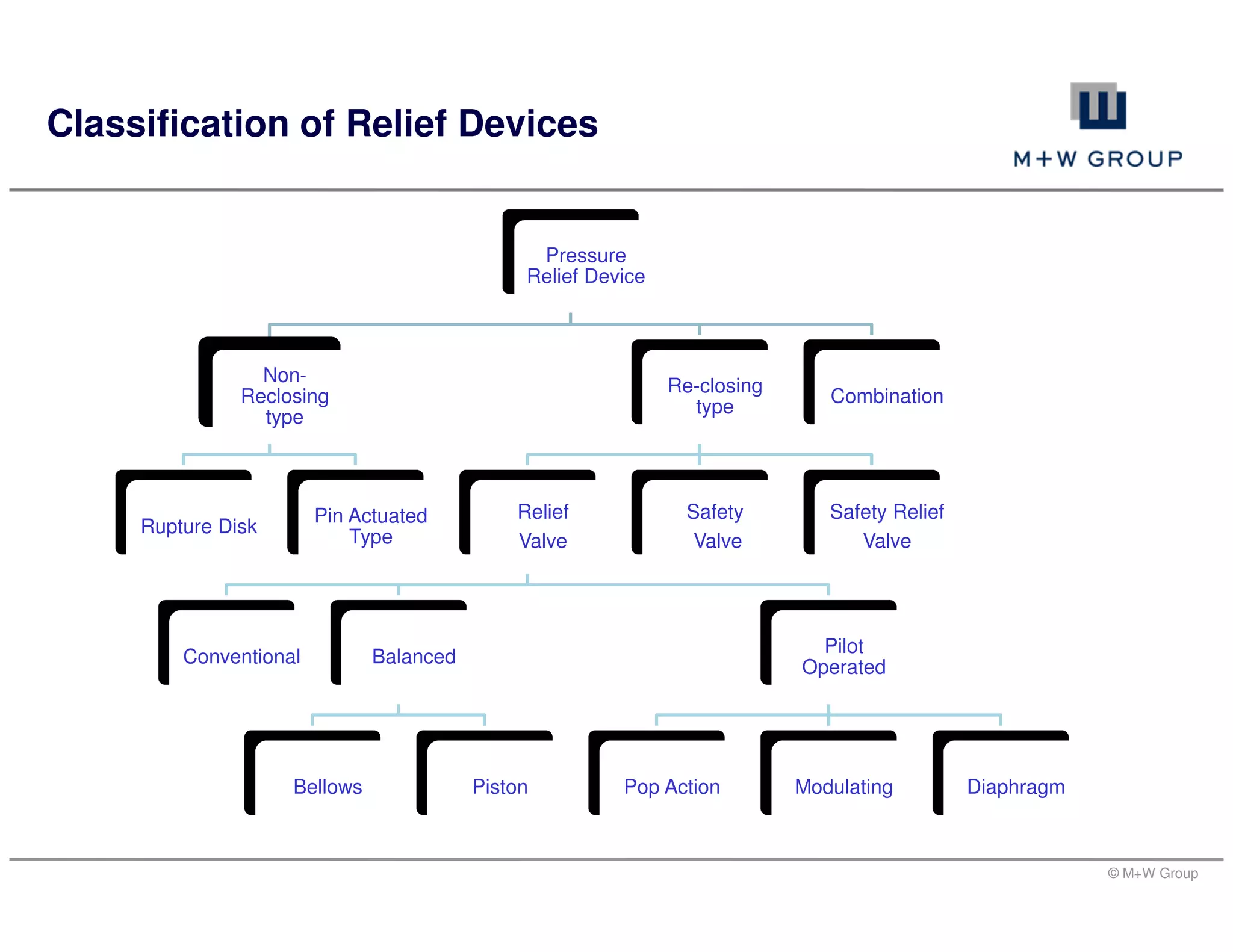
Classification of Relief Devices
Pressure
Relief Device
Non-
Reclosing
type
Rupture Disk
Pin Actuated
Type
Re-closing
type
Relief
Valve
Conventional Balanced
Bellows Piston
Pilot
Operated
Pop Action Modulating Diaphragm
Safety
Valve
Safety Relief
Valve
Combination
© M+W Group
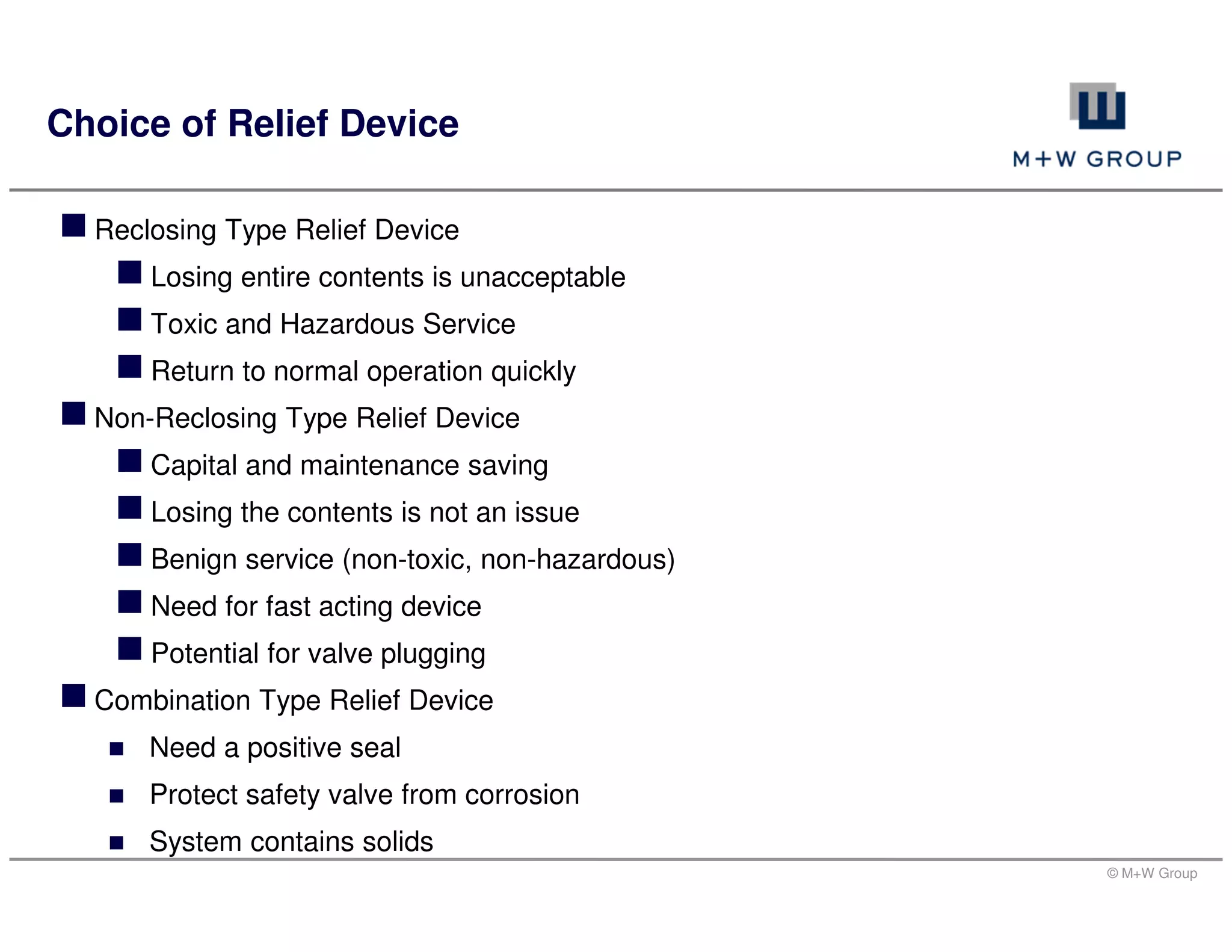
Reclosing Type Relief Device
Losing entire contents is unacceptable
Toxic and Hazardous Service
Return to normal operation quickly
Non-Reclosing Type Relief Device
Capital and maintenance saving
Losing the contents is not an issue
Benign service (non-toxic, non-hazardous)
Need for fast acting device
Potential for valve plugging
Combination Type Relief Device
Need a positive seal
Protect safety valve from corrosion
System contains solids
Choice of Relief Device
© M+W Group
Conventional Safety Valve
© M+W Group
Balanced Bellow Spring Loaded SRV
© M+W Group
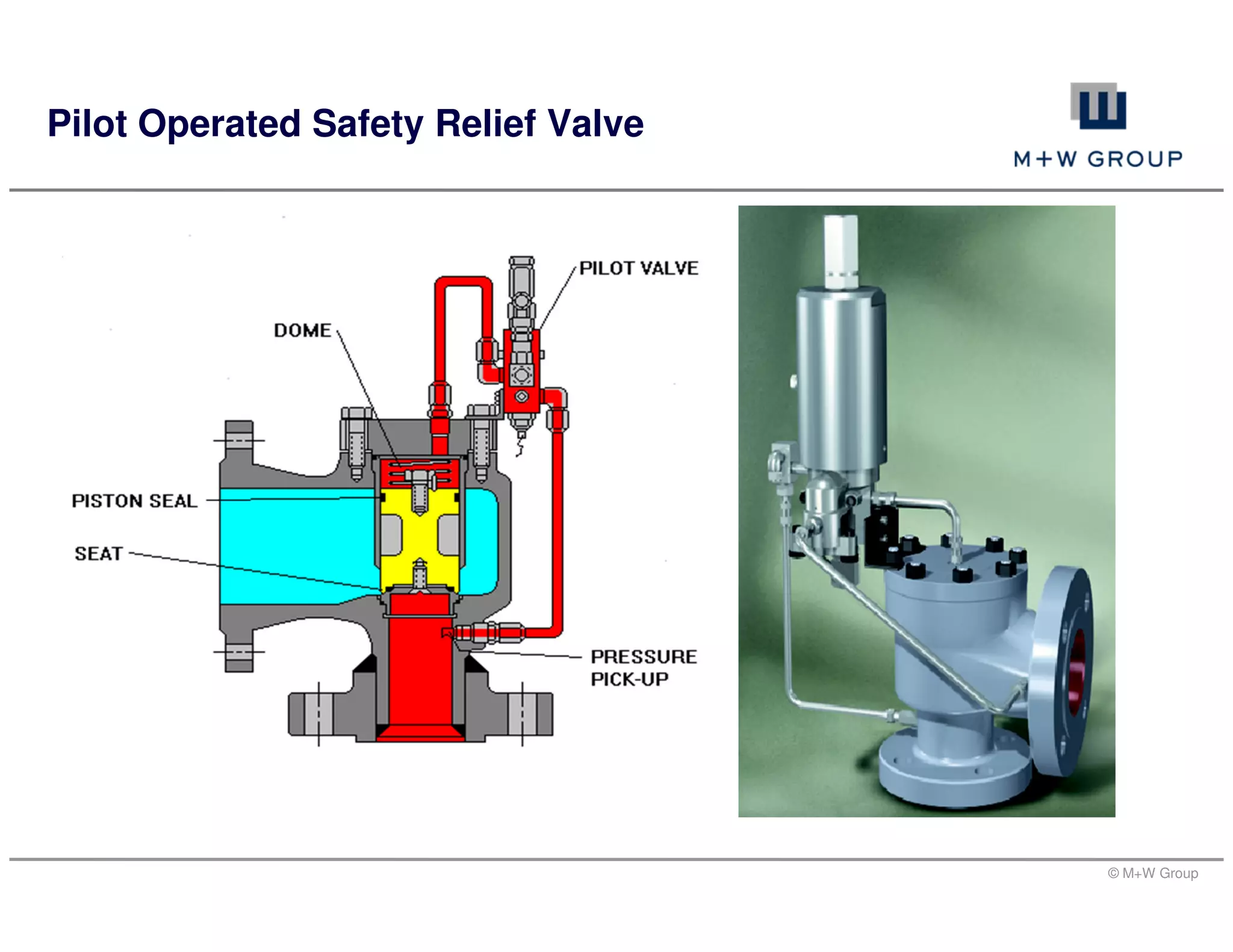
Pilot Operated Safety Relief Valve
© M+W Group
Pilot Operated Safety Relief Valve
POP ACTION & NON - FLOWING TYPE POP ACTION & FLOWING TYPE
© M+W Group
Pilot Operated Safety Relief Valve
MODULATING & NON-FLOWING TYPE MODULATING & FLOWING TYPE
© M+W Group
Terminologies
Operating pressure
MAWP
Design pressure
Set pressure
Accumulation
Overpressure
Blowdown
© M+W Group
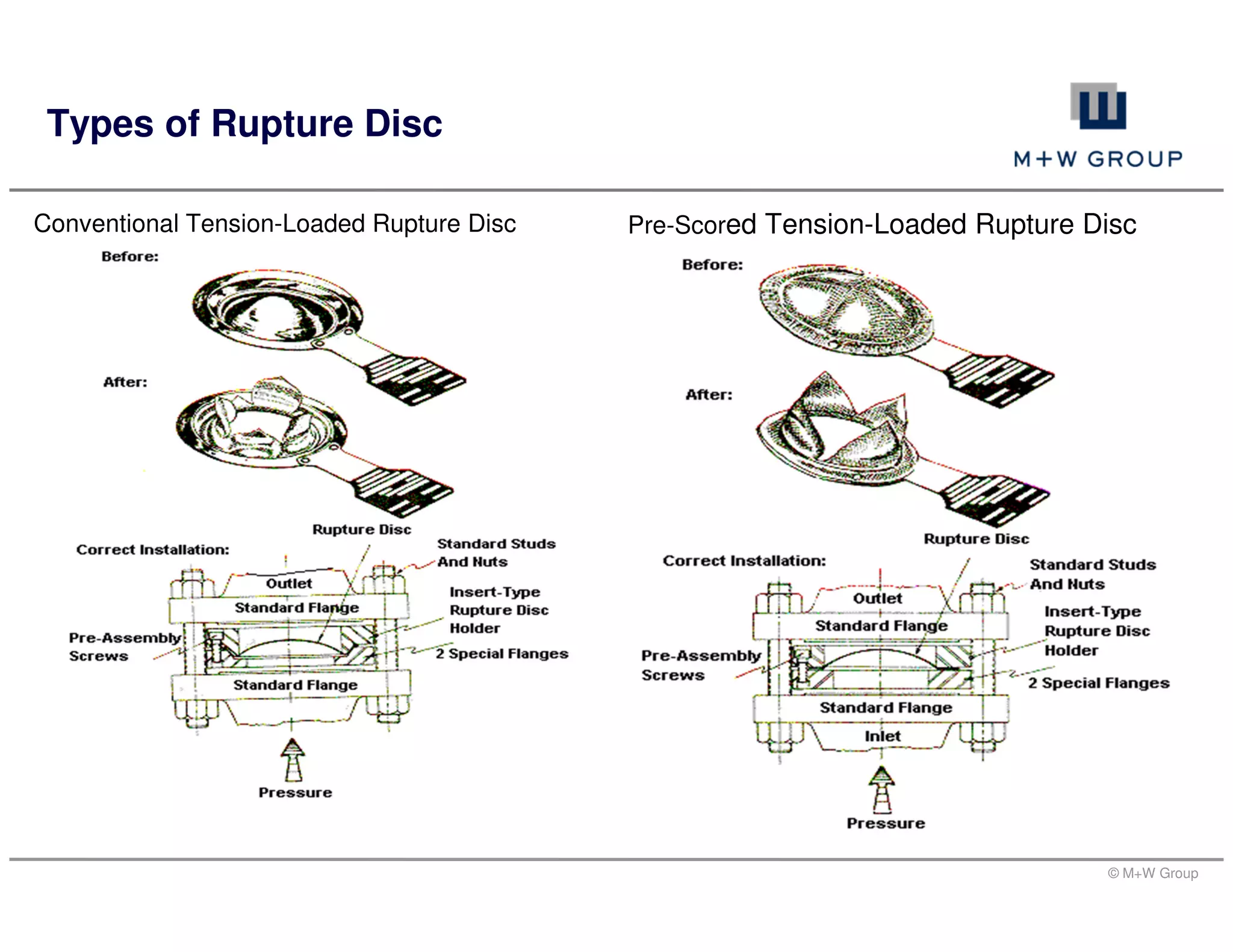
A rupture disc is a thin diaphragm (generally a solid metal disc) designed to rupture
(or burst) at a designated pressure. It is used as a weak element to protect vessels
and piping against excessive pressure (positive or negative).
Reduced fugitive emissions - no simmering or leakage prior to bursting.
Protect against rapid pressure rise.
Less expensive to provide corrosion resistance.
Less tendency to foul or plug.
Types of Rupture Disc
Conventional Tension-Loaded Rupture Disc
Pre-Scored Tension-Loaded Rupture Disc
Rupture Disc
© M+W Group
Types of Rupture Disc
Conventional Tension-Loaded Rupture Disc Pre-Scored Tension-Loaded Rupture Disc
© M+W Group
Relief Scenarios/ Causes of Overpressure
Relief Load Calculations
Relief Valve Sizing
Inlet/ Outlet Line Sizing
Relief Valve Sizing Calculations - Steps
© M+W Group
All the Relief scenarios/ causes are a specific example of
the following variation or multiple variations:
An increase in heat input to a system
A decrease in heat removal from a system
An increase in mass input to a system
A decrease in mass removal from a system
Blocked Outlets
Control Valve Malfunction
Check valve leakage or failure
Utility failure
Electrical/ Power Failure
Cooling Water Failure
Instrument Air Failure
Steam Failure
Inert Gas Failure
Highlighted Scenarios are encountered normally.
Relief Scenarios/ Causes of Overpressure
Loss of Heat
Loss of Instrument air or Electric Instrument
power
Reflux Failure
Abnormal Heat Input
Heat Exchanger Tube Failure
External Fire
Hydraulic Expansion
Process changes/ chemical reactions
© M+W Group
Blocked Outlets
Outlet valve closed
All other valves that are normally open and not affected by primary cause of failure
are open
Consider only the inlet streams having sufficient pressure to open the pressure
relief valve
Capacity to be determined at relieving condition
Control Valve Malfunction
One inlet valve fully open irrespective of its fail safe position
All other valves that are normally open and not affected by primary cause of failure
are open
Capacity to be determined at relieving condition
Vapour blow-by scenario to be checked for liquid level control valves
Scenarios details
© M+W Group
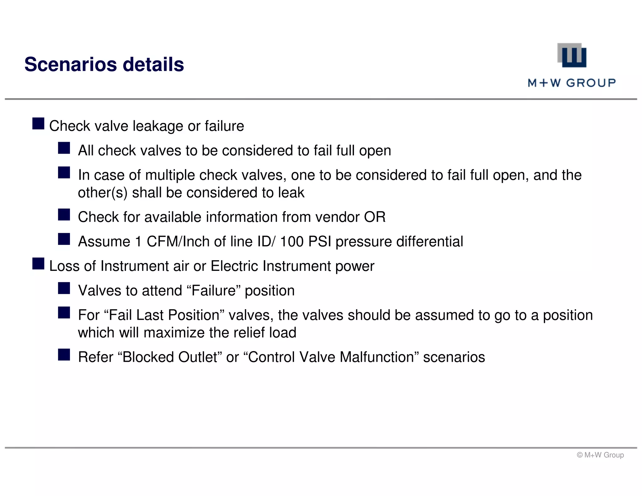
Check valve leakage or failure
All check valves to be considered to fail full open
In case of multiple check valves, one to be considered to fail full open, and the
other(s) shall be considered to leak
Check for available information from vendor OR
Assume 1 CFM/Inch of line ID/ 100 PSI pressure differential
Loss of Instrument air or Electric Instrument power
Valves to attend “Failure” position
For “Fail Last Position” valves, the valves should be assumed to go to a position
which will maximize the relief load
Refer “Blocked Outlet” or “Control Valve Malfunction” scenarios
Scenarios details
© M+W Group
Steam Failure
Steam failure to Turbine drives
Steam failure to Exchangers/ Reboilers
Steam failure to Ejectors
Inert Gas Failure
To Compressor seals
To Catalytic reactors
To Instrument/ equipment purging
Reflux failure
Due to failure of Reflux pump or Closure of valve on reflux line or Loss of duty of
Partial/ Total condenser
Overpressure in Column due to loss of coolant
Calculation of column without reflux is required
Scenarios details
© M+W Group
Abnormal Heat input
Failure of Heat input control device – leading to higher than normal heat input
Clean heat transfer coefficient
Maximum normal temperature of heating medium
Maximum rate of Heater design heat input or burner overdesign
Heat Exchanger Tube failure
The design pressure, of the low pressure side, is less than maximum operating
pressure, of the high pressure side
High pressure fluid is either a vapour or a liquid that will flash on the low pressure
side at relieving conditions
Review chemical reaction, if any
The sudden sharp break of one heat exchanger tube
Flow of high pressure fluid through an opening equal to twice the inside cross
sectional area of a tube
Scenarios details
© M+W Group
External Fire: Effect of Fire on Wetted surface of a vessel
Basis/ assumptions
Flow to/from equipment is stopped
The vessel absorbs heat only through the wetted area walls
All absorbed heat goes into vaporising the contents
No credit is taken for heat removal by condensers or coolers
Equipment wetted surface upto and less than 7.6 m (25 ft) above the source of
flame (exception: spheres)
Fire zone: 2500 to 5000 ft2 ≈ 230 to 460 m2 ≈ 17.2 m to 24.3 m dia circle
Scenarios details
© M+W Group
Set Pressure & Accumulation Limits for PRV’s
Contingency Single Device Installation Multiple Device Installation
Max. Set Pr. % Max. Acc. Pr. % Max. Set Pr. % Max. Acc. Pr. %
Non-fire case
First Relief
device
100 110 100 116
Additional Relief
device(s)
- - 105 116
Fire case
First Relief
device
100 121 100 121
Additional Relief
device(s)
- - 105 121
Supplemental
device
- - 110 121
© M+W Group
Design Procedure for Fire Case
Q = 21,000 x F x A 0.82
Where adequate drainage or firefighting measures do not exist, then the following API
521 equation should be used for calculating Q:
Q = 34,500 x F x A 0.82.
Q = total heat absorption to the wetted surface in BTU/hr (imperial units)
F = environmental factor
A = total wetted surface area in ft2 (imperial units)
F = an environment factor (= 1.0 for bare vessel)
Relief Load Calculations
© M+W Group
Typical Example
Scope:- To Check the Adequacy of the Installed Relief
Device during Emergency Relief with THF fill up & identify
all the events that lead to overpressure for the Reactor
system.
Basis and Assumptions:-
Calculation for reactor will be based on THF.
The Reactor filling is considered upto 80%
For conservative results Design pressure of weakest item in
reactor system is considered as maximum allowable
pressure in system.
Adequate drainage or firefighting measures are exists at
site.
Fire insulation is not considered for reactor.
Safety factor of 20% is considered for calculation.
© M+W Group
External Fire Sizing Basis
Vessel is fill upto 80% fill level, this volume corresponds to a level of 1932mm from
bottom dish fire can impinge on the vessel up to this point.
Calculation
© M+W Group
Head Volume or Volume of
the frustum of a right cone
pi * h * (D^2 + D*d + d^2)/12 (Perry chap-3, p 3-11)
Where h = height, D = large diameter, d = small
diameter
Cone Angle ATAN ( h / (D/2 - d/2)) (Form. Trigonometry)
Surface Area for vessel
(m2) corresponds to 80%
fill level is calculated by
If (Overall Height is <= base depth, then
Vol =
(pi*x*(d^2+d*(d+2*x/TANalpha)+(d+2*x/TANalpha)^2))/
13
Multiplied to Vol =
(pi*x*(3*d^2+6*d*x/TANalpha+4*x^2/TANalpha^2))/12.
So vessel surface area comes out to be 4.5 m2 @ 80% Fill Level.
Calculation
© M+W Group
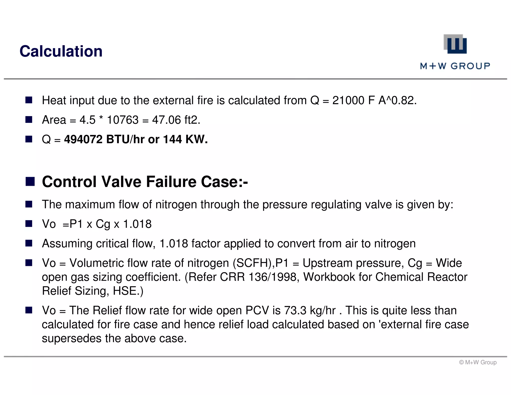
Heat input due to the external fire is calculated from Q = 21000 F A^0.82.
Area = 4.5 * 10763 = 47.06 ft2.
Q = 494072 BTU/hr or 144 KW.
Control Valve Failure Case:-
The maximum flow of nitrogen through the pressure regulating valve is given by:
Vo =P1 x Cg x 1.018
Assuming critical flow, 1.018 factor applied to convert from air to nitrogen
Vo = Volumetric flow rate of nitrogen (SCFH),P1 = Upstream pressure, Cg = Wide
open gas sizing coefficient. (Refer CRR 136/1998, Workbook for Chemical Reactor
Relief Sizing, HSE.)
Vo = The Relief flow rate for wide open PCV is 73.3 kg/hr . This is quite less than
calculated for fire case and hence relief load calculated based on 'external fire case
supersedes the above case.
Calculation
© M+W Group
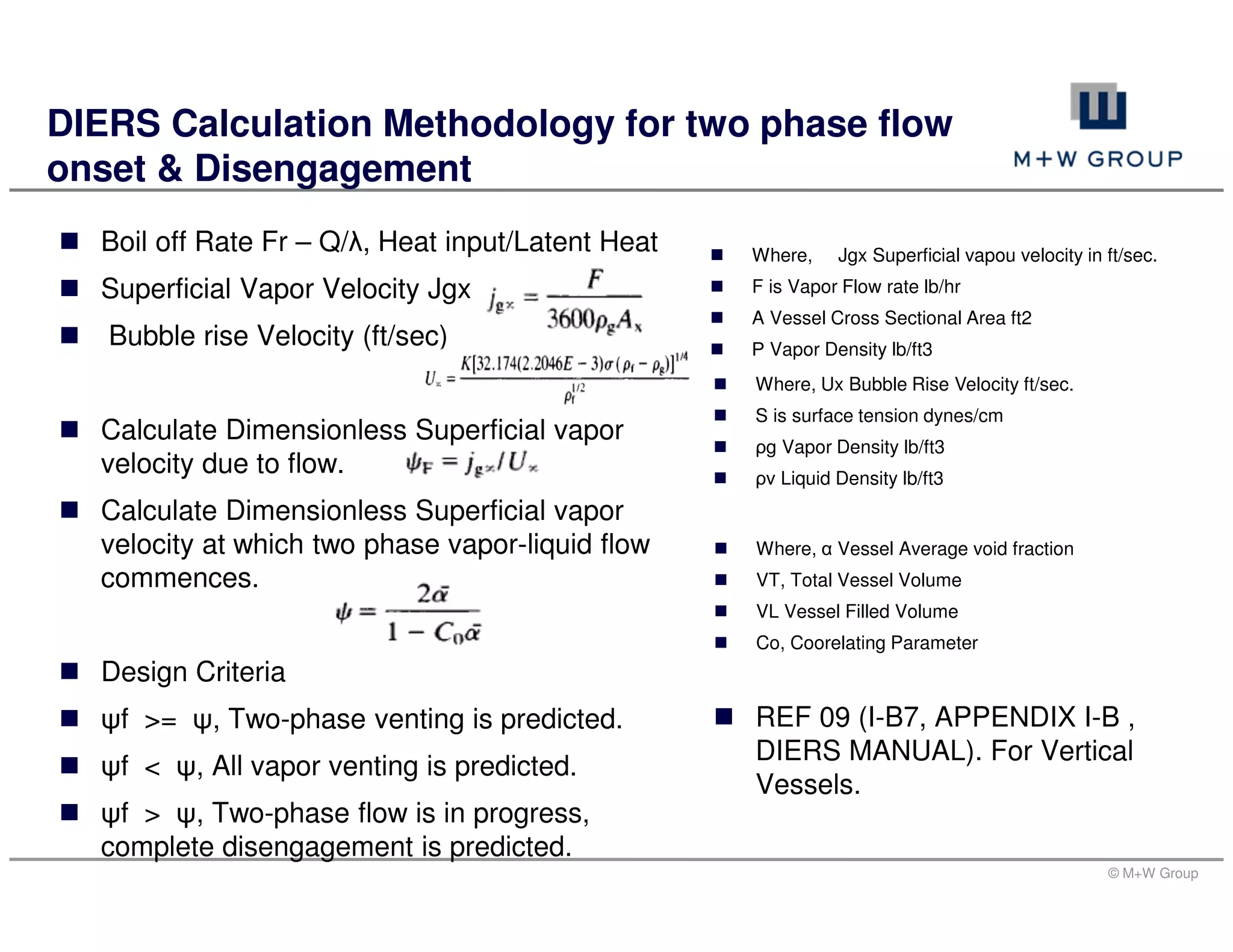
DIERS Calculation Methodology for Two Phase flow onset and Disengagement (for
non -foamy Churn Turbulent Fluid/Bubbly flow and Vertical vessels) is used below in
the calculations.
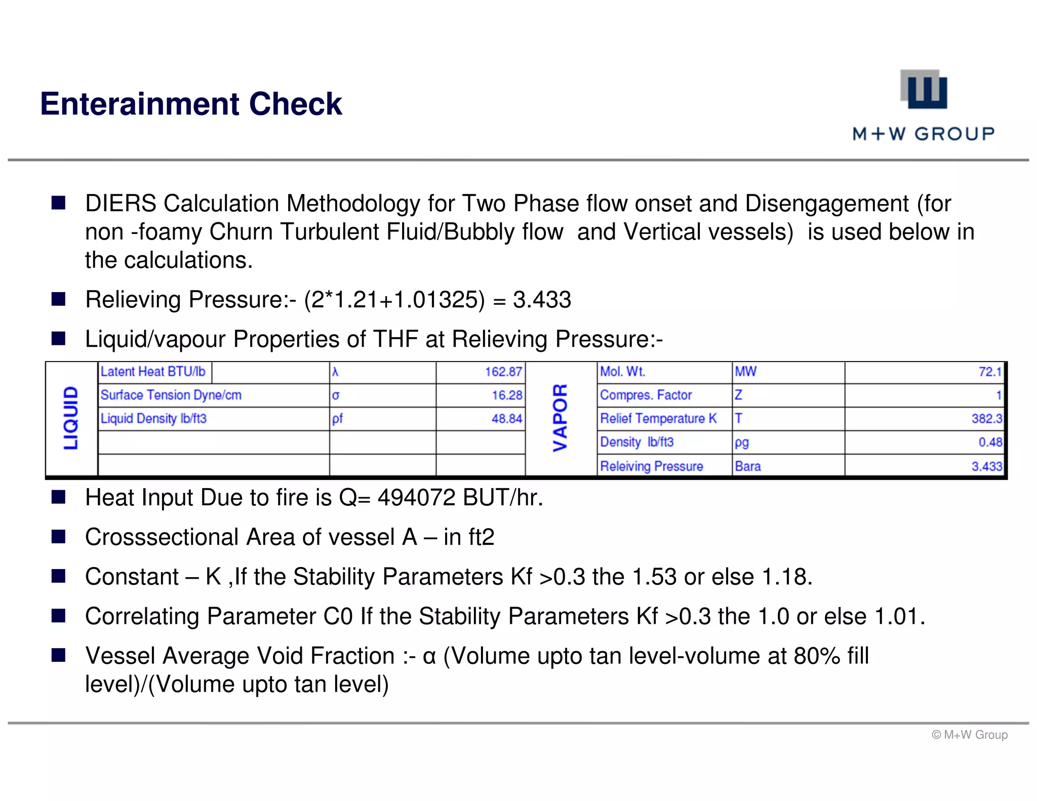
Relieving Pressure:- (2*1.21+1.01325) = 3.433
Liquid/vapour Properties of THF at Relieving Pressure:-
Heat Input Due to fire is Q= 494072 BUT/hr.
Crosssectional Area of vessel A – in ft2
Constant – K ,If the Stability Parameters Kf >0.3 the 1.53 or else 1.18.
Correlating Parameter C0 If the Stability Parameters Kf >0.3 the 1.0 or else 1.01.
Vessel Average Void Fraction :- α (Volume upto tan level-volume at 80% fill
level)/(Volume upto tan level)
Enterainment Check
© M+W Group
Boil off Rate Fr – Q/λ, Heat input/Latent Heat
Superficial Vapor Velocity Jgx
Bubble rise Velocity (ft/sec)
Calculate Dimensionless Superficial vapor
velocity due to flow.
Calculate Dimensionless Superficial vapor
velocity at which two phase vapor-liquid flow
commences.
Design Criteria
ψf >= ψ, Two-phase venting is predicted.
ψf < ψ, All vapor venting is predicted.
ψf > ψ, Two-phase flow is in progress,
complete disengagement is predicted.
DIERS Calculation Methodology for two phase flow
onset & Disengagement
Where, Jgx Superficial vapou velocity in ft/sec.
F is Vapor Flow rate lb/hr
A Vessel Cross Sectional Area ft2
Ρ Vapor Density lb/ft3
Where, Ux Bubble Rise Velocity ft/sec.
S is surface tension dynes/cm
ρg Vapor Density lb/ft3
ρv Liquid Density lb/ft3
Where, α Vessel Average void fraction
VT, Total Vessel Volume
VL Vessel Filled Volume
Co, Coorelating Parameter
REF 09 (I-B7, APPENDIX I-B ,
DIERS MANUAL). For Vertical
Vessels.
© M+W Group
From The DIERS Methodology & Entrainment Check – Single Phase is observed.
Relief flow rate or Boil off Rate = 3034* 0.453 is 1374 Kg/hr
RV set pressure = 2.0 Barg, Max. relief pressure = 3.433 bara
Check for critical / Sub-critical flow through RV using following (Ref 1 - Section 3.6.1.4
Eq 3.1) : .
Pcf/P1 = (2/K+1)^(K/K-1)
Minimum Value of P1 allowing for accumulation is 3.433
Then Pcf 3.433 * 0.57 =1.98 bara This is above atmos. Pressure, so flow regime
through the valve is critical.
Use equation 3.2 from (Ref. API RP 520, Seventh Edition, January 2000) for critical
flow sizing. Area in m2
RV Sizing
Where, K ratio of specific heats .
Pcf is minimum downstream pressure (bara) giving
rise to critical flow
P1 is upstream pressure (bara).
M
TZ
KKPKC
W
cbd 1
13160
© M+W Group
Where C is the flow coefficient, Fig 32 API RP
520, Seventh Edition, January 2000
Required Relief Rate W = 1374 kg/hr
Coefficient of discharge Kd = 0.62 constant
Backpressure correction Kb = 1.0
Combination correction factor Kc = 1.0 for BD
& 0.9 for Relief Valve
Pressure upstream of BD (P1) = 343 Kpa abs
Compressibility factor (Z) = 1.0
Temperature of inlet gas (T) = 382.3
Molecular Weight of Vapour (M) = 72.1
RV Sizing
( ) ( )1/1
1
2
520
−+






+
kk
k
k
Required Area = 593 mm2
Safety Factor 20%
Installed Size = 100 mm
© M+W Group
Relief Valve Selection
Orifice
designation
Orifice area Standard
PSV size
Alternate
PSV sizein² mm²
1 0.062 40.00 3/4 x 1 1 x 1
D 0.110 70.97 1 x 2 1.5 x 2
E 0.196 126.45 1 x 2 1.5 x 2
F 0.307 198.06 1.5 x 2 1.5 x 2.5
G 0.503 324.52 1.5 x 2.5 2 x 3
H 0.785 506.45 1.5 x 3 2 x 3
J 1.287 830.32 2 x 3 3 x 4
K 1.838 1185.80 3 x 4 3 x 6
L 2.853 1840.64 3 x 4 4 x 6
M 3.60 2322.58 4 x 6 -
N 4.34 2799.99 4 x 6 -
P 6.38 4116.12 4 x 6 -
Q 11.05 7129.02 6 x 8 -
R 16.0 10322.6 6 x 8 6 x 10
T 26.0 16774.2 8 x 10 -
© M+W Group
API RP 520, 'Sizing, Selection, and Installation of Pressure-Relieving Devices in
Refineries, Part 1 - Sizing and Selection', Seventh Edition, January 2000.
API RP 521, 'Guide for Pressure-Relieving and Depressuring Systems' Fourth Edition,
March 1997.
PID & GA Drawings
Aspen for Physical Properties
CRR 136/1998, Workbook for Chemical Reactor Relief Sizing, HSE.
DIERs Manual " A perspective on Emergency relief system" by DIER Techincal
Committee.
Guide to Pressure Relief (PSG 8), Part C:Section 5, 1999.
Chemical Engineer's Handbook - Perry, Seventh Edition.
References
© M+W Group
Thank You

More Related Content

What's hot

PSV Sizing.pdf
PSV Sizing.pdfPSV Sizing.pdf
PSV Sizing.pdf
KAhmedRehman
 
Overpressure scenarios overview final
Overpressure scenarios overview finalOverpressure scenarios overview final
Overpressure scenarios overview final
Rajiv Natkar
 
Relief and safety valves for thermal power plants
Relief and safety valves for thermal power plantsRelief and safety valves for thermal power plants
Relief and safety valves for thermal power plants
SHIVAJI CHOUDHURY
 
Ai Ch E Overpressure Protection Training
Ai Ch E Overpressure Protection TrainingAi Ch E Overpressure Protection Training
Ai Ch E Overpressure Protection Training
ernestvictor
 
Safety valve in process industry1
Safety valve in process industry1Safety valve in process industry1
Safety valve in process industry1
Nitesh Chauhan
 
Eng handbook crosby pressure relief valve engineering handbook
Eng handbook crosby pressure relief valve engineering handbookEng handbook crosby pressure relief valve engineering handbook
Eng handbook crosby pressure relief valve engineering handbook
Ali Meshaikhis
 
Pressure safety valves
Pressure safety valvesPressure safety valves
Pressure safety valves
Amol Dudhate
 
Sizing of relief valves for supercritical fluids
Sizing of relief valves for supercritical fluidsSizing of relief valves for supercritical fluids
Sizing of relief valves for supercritical fluids
Alexis Torreele
 
Pressure Safety Valve Sizing - API 520/521/526
Pressure Safety Valve Sizing - API 520/521/526Pressure Safety Valve Sizing - API 520/521/526
Pressure Safety Valve Sizing - API 520/521/526
Vijay Sarathy
 
HTRI PRESENTATION.pdf
HTRI PRESENTATION.pdfHTRI PRESENTATION.pdf
HTRI PRESENTATION.pdf
ssuserbd5784
 
Pressure Vacuum Relief Valve.pptx
Pressure Vacuum Relief Valve.pptxPressure Vacuum Relief Valve.pptx
Pressure Vacuum Relief Valve.pptx
SwamiVidya
 
Accumulation and Over-pressure: difference between accumulation and overpressure
Accumulation and Over-pressure: difference between accumulation and overpressureAccumulation and Over-pressure: difference between accumulation and overpressure
Accumulation and Over-pressure: difference between accumulation and overpressure
Varun Patel
 
CENTRIFUGAL COMPRESSOR SETTLE OUT CONDITIONS TUTORIAL
CENTRIFUGAL COMPRESSOR SETTLE OUT CONDITIONS TUTORIALCENTRIFUGAL COMPRESSOR SETTLE OUT CONDITIONS TUTORIAL
CENTRIFUGAL COMPRESSOR SETTLE OUT CONDITIONS TUTORIAL
Vijay Sarathy
 
flare system design.pdf
flare system design.pdfflare system design.pdf
flare system design.pdf
JahanzaibKhan553038
 
Testing of Safety Valves
Testing of Safety ValvesTesting of Safety Valves
Testing of Safety Valves
Carl Stevens
 
Safety valves
Safety valvesSafety valves
Safety valves
Gaurav Kaushik
 
Relief and blowdown in
Relief and blowdown           inRelief and blowdown           in
Relief and blowdown in
Akshay Kotkar
 
Line sizing
Line sizingLine sizing
Shell and tube heat exchanger design comparison
Shell and tube heat exchanger design comparisonShell and tube heat exchanger design comparison
Shell and tube heat exchanger design comparison
Juan Pablo Hernandez
 
Valves operation and functions complete guide
Valves operation and functions complete guideValves operation and functions complete guide
Valves operation and functions complete guide
Elsayed Amer
 

What's hot (20)

PSV Sizing.pdf
PSV Sizing.pdfPSV Sizing.pdf
PSV Sizing.pdf
 
Overpressure scenarios overview final
Overpressure scenarios overview finalOverpressure scenarios overview final
Overpressure scenarios overview final
 
Relief and safety valves for thermal power plants
Relief and safety valves for thermal power plantsRelief and safety valves for thermal power plants
Relief and safety valves for thermal power plants
 
Ai Ch E Overpressure Protection Training
Ai Ch E Overpressure Protection TrainingAi Ch E Overpressure Protection Training
Ai Ch E Overpressure Protection Training
 
Safety valve in process industry1
Safety valve in process industry1Safety valve in process industry1
Safety valve in process industry1
 
Eng handbook crosby pressure relief valve engineering handbook
Eng handbook crosby pressure relief valve engineering handbookEng handbook crosby pressure relief valve engineering handbook
Eng handbook crosby pressure relief valve engineering handbook
 
Pressure safety valves
Pressure safety valvesPressure safety valves
Pressure safety valves
 
Sizing of relief valves for supercritical fluids
Sizing of relief valves for supercritical fluidsSizing of relief valves for supercritical fluids
Sizing of relief valves for supercritical fluids
 
Pressure Safety Valve Sizing - API 520/521/526
Pressure Safety Valve Sizing - API 520/521/526Pressure Safety Valve Sizing - API 520/521/526
Pressure Safety Valve Sizing - API 520/521/526
 
HTRI PRESENTATION.pdf
HTRI PRESENTATION.pdfHTRI PRESENTATION.pdf
HTRI PRESENTATION.pdf
 
Pressure Vacuum Relief Valve.pptx
Pressure Vacuum Relief Valve.pptxPressure Vacuum Relief Valve.pptx
Pressure Vacuum Relief Valve.pptx
 
Accumulation and Over-pressure: difference between accumulation and overpressure
Accumulation and Over-pressure: difference between accumulation and overpressureAccumulation and Over-pressure: difference between accumulation and overpressure
Accumulation and Over-pressure: difference between accumulation and overpressure
 
CENTRIFUGAL COMPRESSOR SETTLE OUT CONDITIONS TUTORIAL
CENTRIFUGAL COMPRESSOR SETTLE OUT CONDITIONS TUTORIALCENTRIFUGAL COMPRESSOR SETTLE OUT CONDITIONS TUTORIAL
CENTRIFUGAL COMPRESSOR SETTLE OUT CONDITIONS TUTORIAL
 
flare system design.pdf
flare system design.pdfflare system design.pdf
flare system design.pdf
 
Testing of Safety Valves
Testing of Safety ValvesTesting of Safety Valves
Testing of Safety Valves
 
Safety valves
Safety valvesSafety valves
Safety valves
 
Relief and blowdown in
Relief and blowdown           inRelief and blowdown           in
Relief and blowdown in
 
Line sizing
Line sizingLine sizing
Line sizing
 
Shell and tube heat exchanger design comparison
Shell and tube heat exchanger design comparisonShell and tube heat exchanger design comparison
Shell and tube heat exchanger design comparison
 
Valves operation and functions complete guide
Valves operation and functions complete guideValves operation and functions complete guide
Valves operation and functions complete guide
 

Viewers also liked

Revosteam- Coil Type Boiler
Revosteam- Coil Type BoilerRevosteam- Coil Type Boiler
Revosteam- Coil Type Boiler
Thermodyne Engineering systems
 
Api 2000 5th vs 6th final
Api 2000 5th vs 6th finalApi 2000 5th vs 6th final
Api 2000 5th vs 6th final
Paulino israel Chavez Muñoz
 
API 520
API 520API 520
Pressure Relief Systems
Pressure Relief Systems Pressure Relief Systems
Pressure Relief Systems
Gerard B. Hawkins
 
Troubleshooting process operations
Troubleshooting process operationsTroubleshooting process operations
Troubleshooting process operations
Srihari Kodimela
 
Rupture Disks for Process Engineers
Rupture Disks for Process EngineersRupture Disks for Process Engineers
Rupture Disks for Process Engineers
Syed Waqas Haider
 
01 General Control Valves Training.
01 General Control Valves Training.01 General Control Valves Training.
01 General Control Valves Training.
SuryamshVikrama
 
Control Valves
Control ValvesControl Valves
Control Valves
Binit Goenka
 
Control valve ppt
Control valve pptControl valve ppt
Control valve ppt
Tarit Mahata
 
The Top Skills That Can Get You Hired in 2017
The Top Skills That Can Get You Hired in 2017The Top Skills That Can Get You Hired in 2017
The Top Skills That Can Get You Hired in 2017
LinkedIn
 
TEDx Manchester: AI & The Future of Work
TEDx Manchester: AI & The Future of WorkTEDx Manchester: AI & The Future of Work
TEDx Manchester: AI & The Future of Work
Volker Hirsch
 

Viewers also liked (11)

Revosteam- Coil Type Boiler
Revosteam- Coil Type BoilerRevosteam- Coil Type Boiler
Revosteam- Coil Type Boiler
 
Api 2000 5th vs 6th final
Api 2000 5th vs 6th finalApi 2000 5th vs 6th final
Api 2000 5th vs 6th final
 
API 520
API 520API 520
API 520
 
Pressure Relief Systems
Pressure Relief Systems Pressure Relief Systems
Pressure Relief Systems
 
Troubleshooting process operations
Troubleshooting process operationsTroubleshooting process operations
Troubleshooting process operations
 
Rupture Disks for Process Engineers
Rupture Disks for Process EngineersRupture Disks for Process Engineers
Rupture Disks for Process Engineers
 
01 General Control Valves Training.
01 General Control Valves Training.01 General Control Valves Training.
01 General Control Valves Training.
 
Control Valves
Control ValvesControl Valves
Control Valves
 
Control valve ppt
Control valve pptControl valve ppt
Control valve ppt
 
The Top Skills That Can Get You Hired in 2017
The Top Skills That Can Get You Hired in 2017The Top Skills That Can Get You Hired in 2017
The Top Skills That Can Get You Hired in 2017
 
TEDx Manchester: AI & The Future of Work
TEDx Manchester: AI & The Future of WorkTEDx Manchester: AI & The Future of Work
TEDx Manchester: AI & The Future of Work
 

Similar to Pressure Relief Devices_Presenation

Pressure Relief Safety Valves.ppt
Pressure Relief Safety Valves.pptPressure Relief Safety Valves.ppt
Pressure Relief Safety Valves.ppt
varun00000000
 
FINEKAY™ PRESSURE VACUUM RELIEF VALVE GUIDE
FINEKAY™ PRESSURE VACUUM RELIEF VALVE GUIDEFINEKAY™ PRESSURE VACUUM RELIEF VALVE GUIDE
FINEKAY™ PRESSURE VACUUM RELIEF VALVE GUIDE
志强 李
 
pressure-relief-safety-valves.ppt
pressure-relief-safety-valves.pptpressure-relief-safety-valves.ppt
pressure-relief-safety-valves.ppt
NardaPeuelas1
 
pressure-relief-safety-valves.ppt
pressure-relief-safety-valves.pptpressure-relief-safety-valves.ppt
pressure-relief-safety-valves.ppt
PrathapS46
 
Pressure Relief Devices
Pressure Relief DevicesPressure Relief Devices
Pressure Relief Devices
ie-net ingenieursvereniging vzw
 
Module (s 101) شحن غاز التكييفrefrigerant recovering, vacuuming and gas char...
Module (s 101)  شحن غاز التكييفrefrigerant recovering, vacuuming and gas char...Module (s 101)  شحن غاز التكييفrefrigerant recovering, vacuuming and gas char...
Module (s 101) شحن غاز التكييفrefrigerant recovering, vacuuming and gas char...
Juma Yousef J. Saleh جمعة يوسف جمعة صالح
 
All Energy Exhibition & Conference, Glasgow, May 2017
All Energy Exhibition & Conference, Glasgow, May 2017All Energy Exhibition & Conference, Glasgow, May 2017
All Energy Exhibition & Conference, Glasgow, May 2017
Hugo Gallagher (hugo@logis-tech.co.uk)
 
“Antisurge Protection in action” for Compressors By Prem Baboo.pdf
“Antisurge Protection in action” for Compressors By Prem Baboo.pdf“Antisurge Protection in action” for Compressors By Prem Baboo.pdf
“Antisurge Protection in action” for Compressors By Prem Baboo.pdf
PremBaboo4
 
Understanding & Solving Heat Transfer Equipment Stall
Understanding & Solving Heat Transfer Equipment StallUnderstanding & Solving Heat Transfer Equipment Stall
Understanding & Solving Heat Transfer Equipment Stall
Mead O'Brien, Inc.
 
Pneumatic1day
Pneumatic1dayPneumatic1day
Pneumatic1day
Legaspi66
 
pressure relief devices scott ostrowski.ppt
pressure relief devices scott ostrowski.pptpressure relief devices scott ostrowski.ppt
pressure relief devices scott ostrowski.ppt
davidcorm
 
Pressure Safety Valve Type and application
Pressure Safety Valve Type and applicationPressure Safety Valve Type and application
Pressure Safety Valve Type and application
harshadbpande07
 
Fundamentals of Pressure Relief Devices.ppt
Fundamentals of Pressure Relief Devices.pptFundamentals of Pressure Relief Devices.ppt
Fundamentals of Pressure Relief Devices.ppt
LudiDLunar
 
PPT-on-false-air.ppt
PPT-on-false-air.pptPPT-on-false-air.ppt
PPT-on-false-air.ppt
vikramparuthi1
 
Yankee safety by_dk_singhal
Yankee safety by_dk_singhalYankee safety by_dk_singhal
Yankee safety by_dk_singhal
Devesh Singhal
 
Centrifugal Compressor System Design & Simulation
Centrifugal Compressor System Design & SimulationCentrifugal Compressor System Design & Simulation
Centrifugal Compressor System Design & Simulation
Vijay Sarathy
 
The Humble Check Valve
The Humble Check ValveThe Humble Check Valve
The Humble Check Valve
blenrayaust
 
Trf ptc
Trf ptcTrf ptc
First fare 2011 overview of pneumatics-2012
First fare 2011 overview of pneumatics-2012First fare 2011 overview of pneumatics-2012
First fare 2011 overview of pneumatics-2012
Oregon FIRST Robotics
 
Document on Deisel And Gas Engine
Document on Deisel And Gas EngineDocument on Deisel And Gas Engine
Document on Deisel And Gas Engine
Malik Zaid
 

Similar to Pressure Relief Devices_Presenation (20)

Pressure Relief Safety Valves.ppt
Pressure Relief Safety Valves.pptPressure Relief Safety Valves.ppt
Pressure Relief Safety Valves.ppt
 
FINEKAY™ PRESSURE VACUUM RELIEF VALVE GUIDE
FINEKAY™ PRESSURE VACUUM RELIEF VALVE GUIDEFINEKAY™ PRESSURE VACUUM RELIEF VALVE GUIDE
FINEKAY™ PRESSURE VACUUM RELIEF VALVE GUIDE
 
pressure-relief-safety-valves.ppt
pressure-relief-safety-valves.pptpressure-relief-safety-valves.ppt
pressure-relief-safety-valves.ppt
 
pressure-relief-safety-valves.ppt
pressure-relief-safety-valves.pptpressure-relief-safety-valves.ppt
pressure-relief-safety-valves.ppt
 
Pressure Relief Devices
Pressure Relief DevicesPressure Relief Devices
Pressure Relief Devices
 
Module (s 101) شحن غاز التكييفrefrigerant recovering, vacuuming and gas char...
Module (s 101)  شحن غاز التكييفrefrigerant recovering, vacuuming and gas char...Module (s 101)  شحن غاز التكييفrefrigerant recovering, vacuuming and gas char...
Module (s 101) شحن غاز التكييفrefrigerant recovering, vacuuming and gas char...
 
All Energy Exhibition & Conference, Glasgow, May 2017
All Energy Exhibition & Conference, Glasgow, May 2017All Energy Exhibition & Conference, Glasgow, May 2017
All Energy Exhibition & Conference, Glasgow, May 2017
 
“Antisurge Protection in action” for Compressors By Prem Baboo.pdf
“Antisurge Protection in action” for Compressors By Prem Baboo.pdf“Antisurge Protection in action” for Compressors By Prem Baboo.pdf
“Antisurge Protection in action” for Compressors By Prem Baboo.pdf
 
Understanding & Solving Heat Transfer Equipment Stall
Understanding & Solving Heat Transfer Equipment StallUnderstanding & Solving Heat Transfer Equipment Stall
Understanding & Solving Heat Transfer Equipment Stall
 
Pneumatic1day
Pneumatic1dayPneumatic1day
Pneumatic1day
 
pressure relief devices scott ostrowski.ppt
pressure relief devices scott ostrowski.pptpressure relief devices scott ostrowski.ppt
pressure relief devices scott ostrowski.ppt
 
Pressure Safety Valve Type and application
Pressure Safety Valve Type and applicationPressure Safety Valve Type and application
Pressure Safety Valve Type and application
 
Fundamentals of Pressure Relief Devices.ppt
Fundamentals of Pressure Relief Devices.pptFundamentals of Pressure Relief Devices.ppt
Fundamentals of Pressure Relief Devices.ppt
 
PPT-on-false-air.ppt
PPT-on-false-air.pptPPT-on-false-air.ppt
PPT-on-false-air.ppt
 
Yankee safety by_dk_singhal
Yankee safety by_dk_singhalYankee safety by_dk_singhal
Yankee safety by_dk_singhal
 
Centrifugal Compressor System Design & Simulation
Centrifugal Compressor System Design & SimulationCentrifugal Compressor System Design & Simulation
Centrifugal Compressor System Design & Simulation
 
The Humble Check Valve
The Humble Check ValveThe Humble Check Valve
The Humble Check Valve
 
Trf ptc
Trf ptcTrf ptc
Trf ptc
 
First fare 2011 overview of pneumatics-2012
First fare 2011 overview of pneumatics-2012First fare 2011 overview of pneumatics-2012
First fare 2011 overview of pneumatics-2012
 
Document on Deisel And Gas Engine
Document on Deisel And Gas EngineDocument on Deisel And Gas Engine
Document on Deisel And Gas Engine
 

Pressure Relief Devices_Presenation

  • 1. M+W Group-India Pressure Relief Devices-Basics & Sample Calculation 14th Jan2016
  • 2. © M+W Group Relief Device requirement & components. Classification & Types of relief devices. Rupture Disc & types of RD’s Relief Scenarios & cause of over pressure. Relief Device Calculation Steps. Relief Device Selection Agenda
  • 4. © M+W Group Pressure Relief Devices Why Relief Devices are Required? Relief Devices are required for following reasons: To protect personnel from the dangers of over pressurizing equipment To minimize chemical losses during pressure upsets To prevent damage to equipment To prevent damage to adjoining property To reduce insurance premiums, and To comply with governmental regulations Components of Relief System Relief Device, and Associated lines and process equipment to safely handle the material ejected.
  • 5. © M+W Group Knock out Drum Cyclone Separator Condenser Scrubber Flare Incinerator Relief Discharges- Atmosphere & Effluent System
  • 6. © M+W Group Relief Valve Opens normally in proportion to the pressure increase Used primarily with incompressible fluids. Safety Valve Characterized by rapid opening or pop action Normally used with compressible fluids Safety Relief Valve Spring loaded pressure relief valve that may be used either as safety or relief depending on the type of application Set Pressure Inlet gauge pressure at which the device is set to open Overpressure Pressure increase over the set pressure of the device to achieve rated flow Overpressure = Accumulation, when the Set pressure = MAWP Terminologies
  • 7. © M+W Group Classification of Relief Devices Pressure Relief Device Non- Reclosing type Rupture Disk Pin Actuated Type Re-closing type Relief Valve Conventional Balanced Bellows Piston Pilot Operated Pop Action Modulating Diaphragm Safety Valve Safety Relief Valve Combination
  • 8. © M+W Group Reclosing Type Relief Device Losing entire contents is unacceptable Toxic and Hazardous Service Return to normal operation quickly Non-Reclosing Type Relief Device Capital and maintenance saving Losing the contents is not an issue Benign service (non-toxic, non-hazardous) Need for fast acting device Potential for valve plugging Combination Type Relief Device Need a positive seal Protect safety valve from corrosion System contains solids Choice of Relief Device
  • 10. © M+W Group Balanced Bellow Spring Loaded SRV
  • 11. © M+W Group Pilot Operated Safety Relief Valve
  • 12. © M+W Group Pilot Operated Safety Relief Valve POP ACTION & NON - FLOWING TYPE POP ACTION & FLOWING TYPE
  • 13. © M+W Group Pilot Operated Safety Relief Valve MODULATING & NON-FLOWING TYPE MODULATING & FLOWING TYPE
  • 14. © M+W Group Terminologies Operating pressure MAWP Design pressure Set pressure Accumulation Overpressure Blowdown
  • 15. © M+W Group A rupture disc is a thin diaphragm (generally a solid metal disc) designed to rupture (or burst) at a designated pressure. It is used as a weak element to protect vessels and piping against excessive pressure (positive or negative). Reduced fugitive emissions - no simmering or leakage prior to bursting. Protect against rapid pressure rise. Less expensive to provide corrosion resistance. Less tendency to foul or plug. Types of Rupture Disc Conventional Tension-Loaded Rupture Disc Pre-Scored Tension-Loaded Rupture Disc Rupture Disc
  • 16. © M+W Group Types of Rupture Disc Conventional Tension-Loaded Rupture Disc Pre-Scored Tension-Loaded Rupture Disc
  • 17. © M+W Group Relief Scenarios/ Causes of Overpressure Relief Load Calculations Relief Valve Sizing Inlet/ Outlet Line Sizing Relief Valve Sizing Calculations - Steps
  • 18. © M+W Group All the Relief scenarios/ causes are a specific example of the following variation or multiple variations: An increase in heat input to a system A decrease in heat removal from a system An increase in mass input to a system A decrease in mass removal from a system Blocked Outlets Control Valve Malfunction Check valve leakage or failure Utility failure Electrical/ Power Failure Cooling Water Failure Instrument Air Failure Steam Failure Inert Gas Failure Highlighted Scenarios are encountered normally. Relief Scenarios/ Causes of Overpressure Loss of Heat Loss of Instrument air or Electric Instrument power Reflux Failure Abnormal Heat Input Heat Exchanger Tube Failure External Fire Hydraulic Expansion Process changes/ chemical reactions
  • 19. © M+W Group Blocked Outlets Outlet valve closed All other valves that are normally open and not affected by primary cause of failure are open Consider only the inlet streams having sufficient pressure to open the pressure relief valve Capacity to be determined at relieving condition Control Valve Malfunction One inlet valve fully open irrespective of its fail safe position All other valves that are normally open and not affected by primary cause of failure are open Capacity to be determined at relieving condition Vapour blow-by scenario to be checked for liquid level control valves Scenarios details
  • 20. © M+W Group Check valve leakage or failure All check valves to be considered to fail full open In case of multiple check valves, one to be considered to fail full open, and the other(s) shall be considered to leak Check for available information from vendor OR Assume 1 CFM/Inch of line ID/ 100 PSI pressure differential Loss of Instrument air or Electric Instrument power Valves to attend “Failure” position For “Fail Last Position” valves, the valves should be assumed to go to a position which will maximize the relief load Refer “Blocked Outlet” or “Control Valve Malfunction” scenarios Scenarios details
  • 21. © M+W Group Steam Failure Steam failure to Turbine drives Steam failure to Exchangers/ Reboilers Steam failure to Ejectors Inert Gas Failure To Compressor seals To Catalytic reactors To Instrument/ equipment purging Reflux failure Due to failure of Reflux pump or Closure of valve on reflux line or Loss of duty of Partial/ Total condenser Overpressure in Column due to loss of coolant Calculation of column without reflux is required Scenarios details
  • 22. © M+W Group Abnormal Heat input Failure of Heat input control device – leading to higher than normal heat input Clean heat transfer coefficient Maximum normal temperature of heating medium Maximum rate of Heater design heat input or burner overdesign Heat Exchanger Tube failure The design pressure, of the low pressure side, is less than maximum operating pressure, of the high pressure side High pressure fluid is either a vapour or a liquid that will flash on the low pressure side at relieving conditions Review chemical reaction, if any The sudden sharp break of one heat exchanger tube Flow of high pressure fluid through an opening equal to twice the inside cross sectional area of a tube Scenarios details
  • 23. © M+W Group External Fire: Effect of Fire on Wetted surface of a vessel Basis/ assumptions Flow to/from equipment is stopped The vessel absorbs heat only through the wetted area walls All absorbed heat goes into vaporising the contents No credit is taken for heat removal by condensers or coolers Equipment wetted surface upto and less than 7.6 m (25 ft) above the source of flame (exception: spheres) Fire zone: 2500 to 5000 ft2 ≈ 230 to 460 m2 ≈ 17.2 m to 24.3 m dia circle Scenarios details
  • 24. © M+W Group Set Pressure & Accumulation Limits for PRV’s Contingency Single Device Installation Multiple Device Installation Max. Set Pr. % Max. Acc. Pr. % Max. Set Pr. % Max. Acc. Pr. % Non-fire case First Relief device 100 110 100 116 Additional Relief device(s) - - 105 116 Fire case First Relief device 100 121 100 121 Additional Relief device(s) - - 105 121 Supplemental device - - 110 121
  • 25. © M+W Group Design Procedure for Fire Case Q = 21,000 x F x A 0.82 Where adequate drainage or firefighting measures do not exist, then the following API 521 equation should be used for calculating Q: Q = 34,500 x F x A 0.82. Q = total heat absorption to the wetted surface in BTU/hr (imperial units) F = environmental factor A = total wetted surface area in ft2 (imperial units) F = an environment factor (= 1.0 for bare vessel) Relief Load Calculations
  • 26. © M+W Group Typical Example Scope:- To Check the Adequacy of the Installed Relief Device during Emergency Relief with THF fill up & identify all the events that lead to overpressure for the Reactor system. Basis and Assumptions:- Calculation for reactor will be based on THF. The Reactor filling is considered upto 80% For conservative results Design pressure of weakest item in reactor system is considered as maximum allowable pressure in system. Adequate drainage or firefighting measures are exists at site. Fire insulation is not considered for reactor. Safety factor of 20% is considered for calculation.
  • 27. © M+W Group External Fire Sizing Basis Vessel is fill upto 80% fill level, this volume corresponds to a level of 1932mm from bottom dish fire can impinge on the vessel up to this point. Calculation
  • 28. © M+W Group Head Volume or Volume of the frustum of a right cone pi * h * (D^2 + D*d + d^2)/12 (Perry chap-3, p 3-11) Where h = height, D = large diameter, d = small diameter Cone Angle ATAN ( h / (D/2 - d/2)) (Form. Trigonometry) Surface Area for vessel (m2) corresponds to 80% fill level is calculated by If (Overall Height is <= base depth, then Vol = (pi*x*(d^2+d*(d+2*x/TANalpha)+(d+2*x/TANalpha)^2))/ 13 Multiplied to Vol = (pi*x*(3*d^2+6*d*x/TANalpha+4*x^2/TANalpha^2))/12. So vessel surface area comes out to be 4.5 m2 @ 80% Fill Level. Calculation
  • 29. © M+W Group Heat input due to the external fire is calculated from Q = 21000 F A^0.82. Area = 4.5 * 10763 = 47.06 ft2. Q = 494072 BTU/hr or 144 KW. Control Valve Failure Case:- The maximum flow of nitrogen through the pressure regulating valve is given by: Vo =P1 x Cg x 1.018 Assuming critical flow, 1.018 factor applied to convert from air to nitrogen Vo = Volumetric flow rate of nitrogen (SCFH),P1 = Upstream pressure, Cg = Wide open gas sizing coefficient. (Refer CRR 136/1998, Workbook for Chemical Reactor Relief Sizing, HSE.) Vo = The Relief flow rate for wide open PCV is 73.3 kg/hr . This is quite less than calculated for fire case and hence relief load calculated based on 'external fire case supersedes the above case. Calculation
  • 30. © M+W Group DIERS Calculation Methodology for Two Phase flow onset and Disengagement (for non -foamy Churn Turbulent Fluid/Bubbly flow and Vertical vessels) is used below in the calculations. Relieving Pressure:- (2*1.21+1.01325) = 3.433 Liquid/vapour Properties of THF at Relieving Pressure:- Heat Input Due to fire is Q= 494072 BUT/hr. Crosssectional Area of vessel A – in ft2 Constant – K ,If the Stability Parameters Kf >0.3 the 1.53 or else 1.18. Correlating Parameter C0 If the Stability Parameters Kf >0.3 the 1.0 or else 1.01. Vessel Average Void Fraction :- α (Volume upto tan level-volume at 80% fill level)/(Volume upto tan level) Enterainment Check
  • 31. © M+W Group Boil off Rate Fr – Q/λ, Heat input/Latent Heat Superficial Vapor Velocity Jgx Bubble rise Velocity (ft/sec) Calculate Dimensionless Superficial vapor velocity due to flow. Calculate Dimensionless Superficial vapor velocity at which two phase vapor-liquid flow commences. Design Criteria ψf >= ψ, Two-phase venting is predicted. ψf < ψ, All vapor venting is predicted. ψf > ψ, Two-phase flow is in progress, complete disengagement is predicted. DIERS Calculation Methodology for two phase flow onset & Disengagement Where, Jgx Superficial vapou velocity in ft/sec. F is Vapor Flow rate lb/hr A Vessel Cross Sectional Area ft2 Ρ Vapor Density lb/ft3 Where, Ux Bubble Rise Velocity ft/sec. S is surface tension dynes/cm ρg Vapor Density lb/ft3 ρv Liquid Density lb/ft3 Where, α Vessel Average void fraction VT, Total Vessel Volume VL Vessel Filled Volume Co, Coorelating Parameter REF 09 (I-B7, APPENDIX I-B , DIERS MANUAL). For Vertical Vessels.
  • 32. © M+W Group From The DIERS Methodology & Entrainment Check – Single Phase is observed. Relief flow rate or Boil off Rate = 3034* 0.453 is 1374 Kg/hr RV set pressure = 2.0 Barg, Max. relief pressure = 3.433 bara Check for critical / Sub-critical flow through RV using following (Ref 1 - Section 3.6.1.4 Eq 3.1) : . Pcf/P1 = (2/K+1)^(K/K-1) Minimum Value of P1 allowing for accumulation is 3.433 Then Pcf 3.433 * 0.57 =1.98 bara This is above atmos. Pressure, so flow regime through the valve is critical. Use equation 3.2 from (Ref. API RP 520, Seventh Edition, January 2000) for critical flow sizing. Area in m2 RV Sizing Where, K ratio of specific heats . Pcf is minimum downstream pressure (bara) giving rise to critical flow P1 is upstream pressure (bara). M TZ KKPKC W cbd 1 13160
  • 33. © M+W Group Where C is the flow coefficient, Fig 32 API RP 520, Seventh Edition, January 2000 Required Relief Rate W = 1374 kg/hr Coefficient of discharge Kd = 0.62 constant Backpressure correction Kb = 1.0 Combination correction factor Kc = 1.0 for BD & 0.9 for Relief Valve Pressure upstream of BD (P1) = 343 Kpa abs Compressibility factor (Z) = 1.0 Temperature of inlet gas (T) = 382.3 Molecular Weight of Vapour (M) = 72.1 RV Sizing ( ) ( )1/1 1 2 520 −+       + kk k k Required Area = 593 mm2 Safety Factor 20% Installed Size = 100 mm
  • 34. © M+W Group Relief Valve Selection Orifice designation Orifice area Standard PSV size Alternate PSV sizein² mm² 1 0.062 40.00 3/4 x 1 1 x 1 D 0.110 70.97 1 x 2 1.5 x 2 E 0.196 126.45 1 x 2 1.5 x 2 F 0.307 198.06 1.5 x 2 1.5 x 2.5 G 0.503 324.52 1.5 x 2.5 2 x 3 H 0.785 506.45 1.5 x 3 2 x 3 J 1.287 830.32 2 x 3 3 x 4 K 1.838 1185.80 3 x 4 3 x 6 L 2.853 1840.64 3 x 4 4 x 6 M 3.60 2322.58 4 x 6 - N 4.34 2799.99 4 x 6 - P 6.38 4116.12 4 x 6 - Q 11.05 7129.02 6 x 8 - R 16.0 10322.6 6 x 8 6 x 10 T 26.0 16774.2 8 x 10 -
  • 35. © M+W Group API RP 520, 'Sizing, Selection, and Installation of Pressure-Relieving Devices in Refineries, Part 1 - Sizing and Selection', Seventh Edition, January 2000. API RP 521, 'Guide for Pressure-Relieving and Depressuring Systems' Fourth Edition, March 1997. PID & GA Drawings Aspen for Physical Properties CRR 136/1998, Workbook for Chemical Reactor Relief Sizing, HSE. DIERs Manual " A perspective on Emergency relief system" by DIER Techincal Committee. Guide to Pressure Relief (PSG 8), Part C:Section 5, 1999. Chemical Engineer's Handbook - Perry, Seventh Edition. References