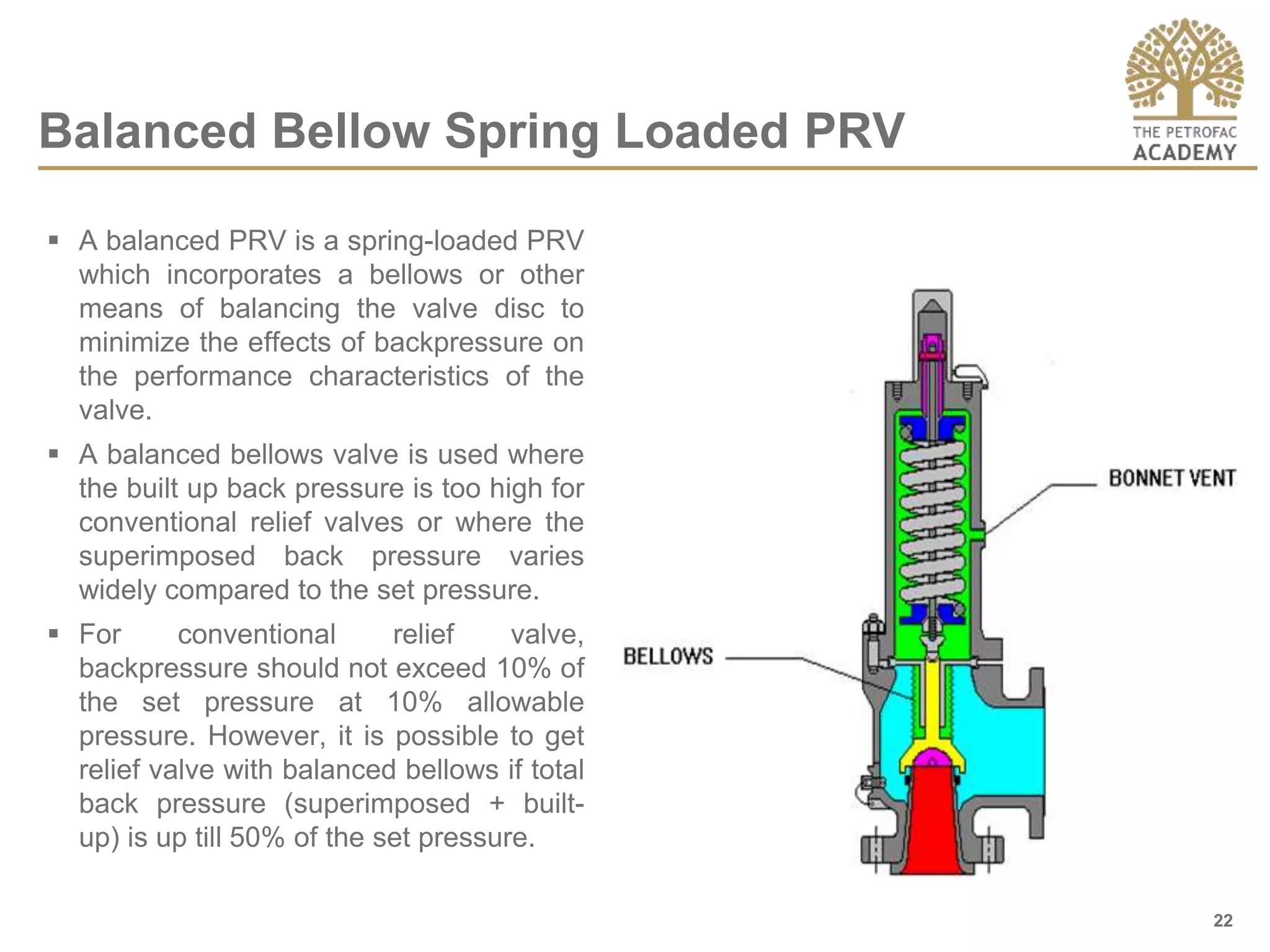
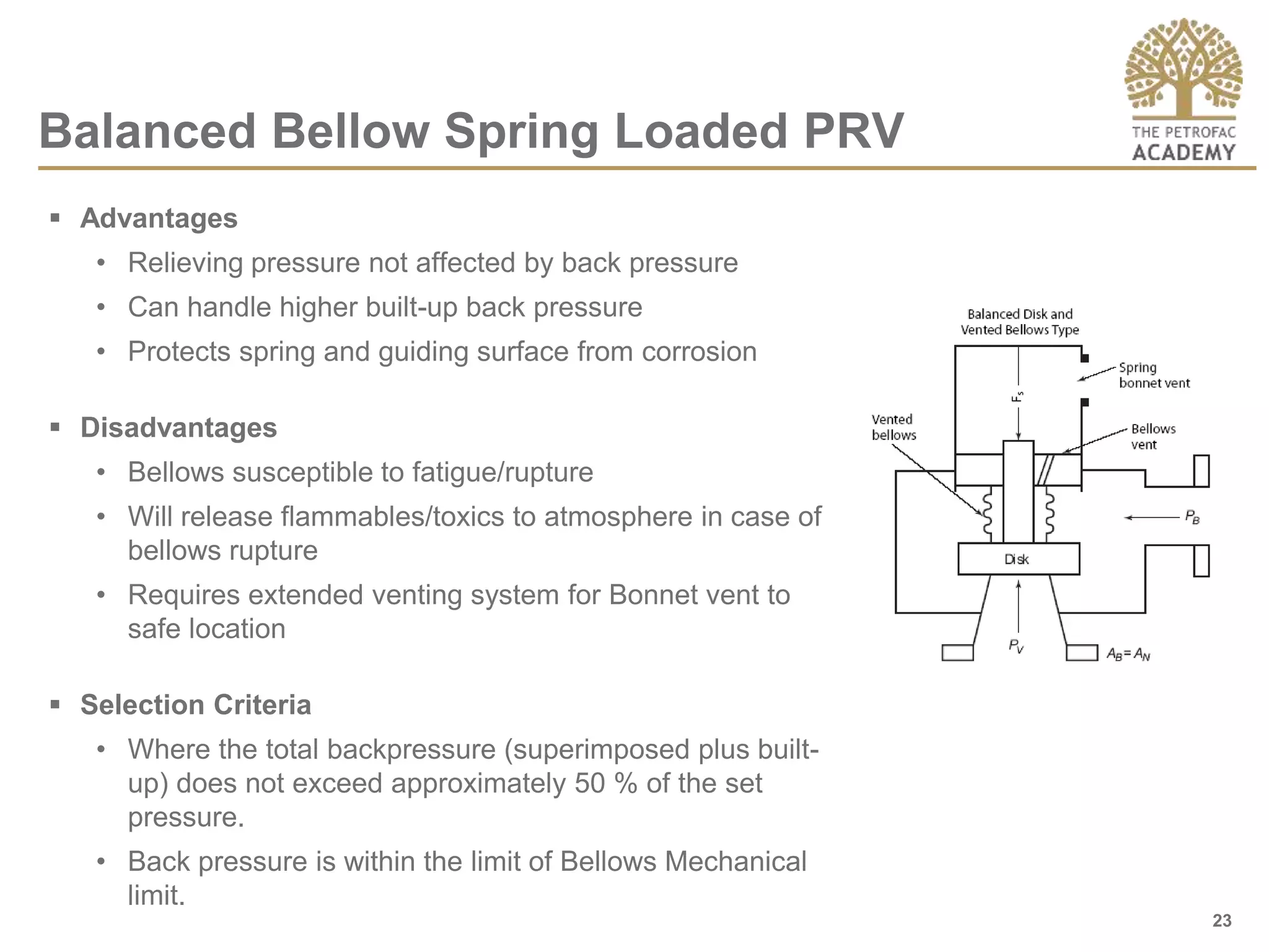
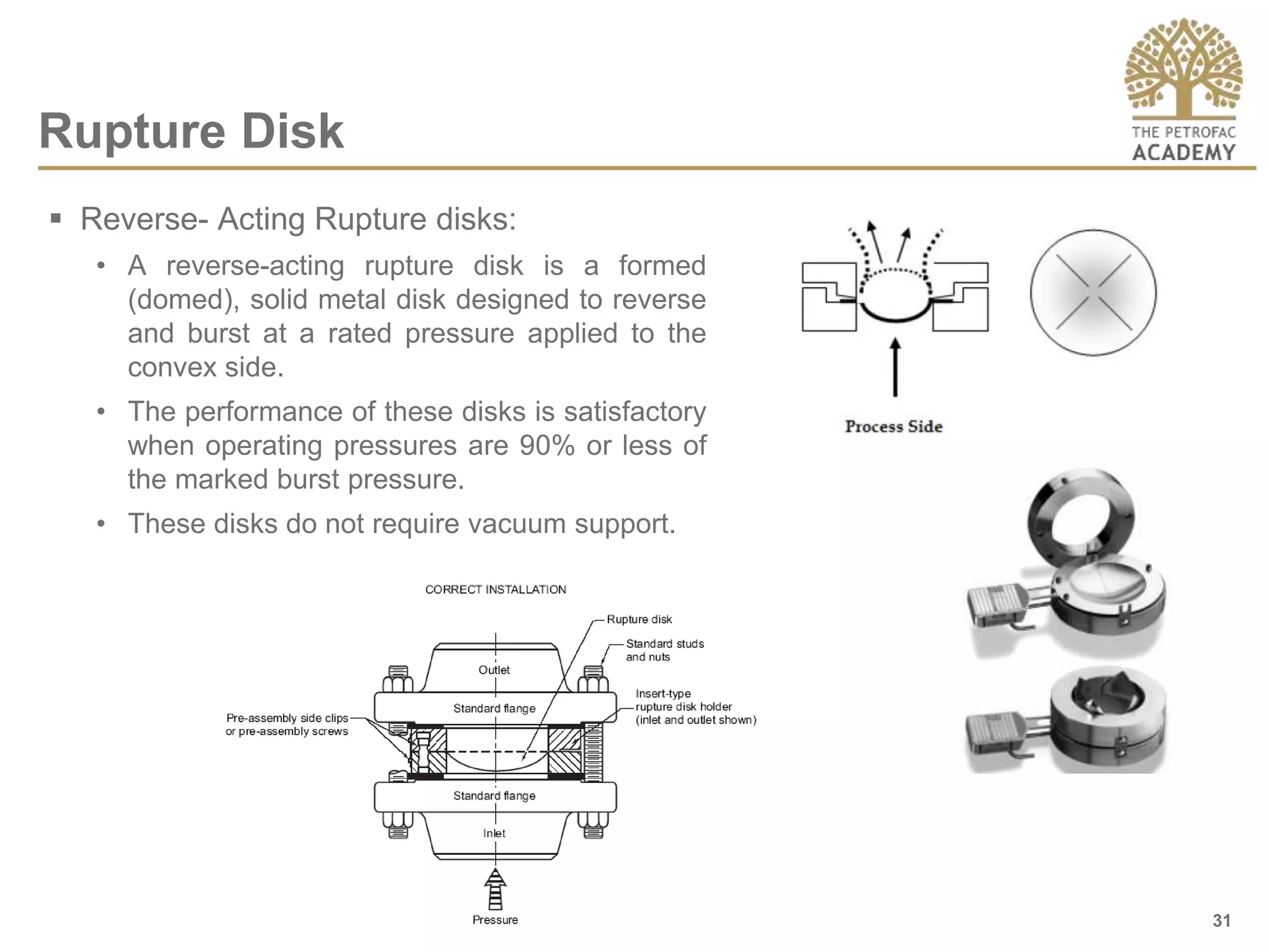
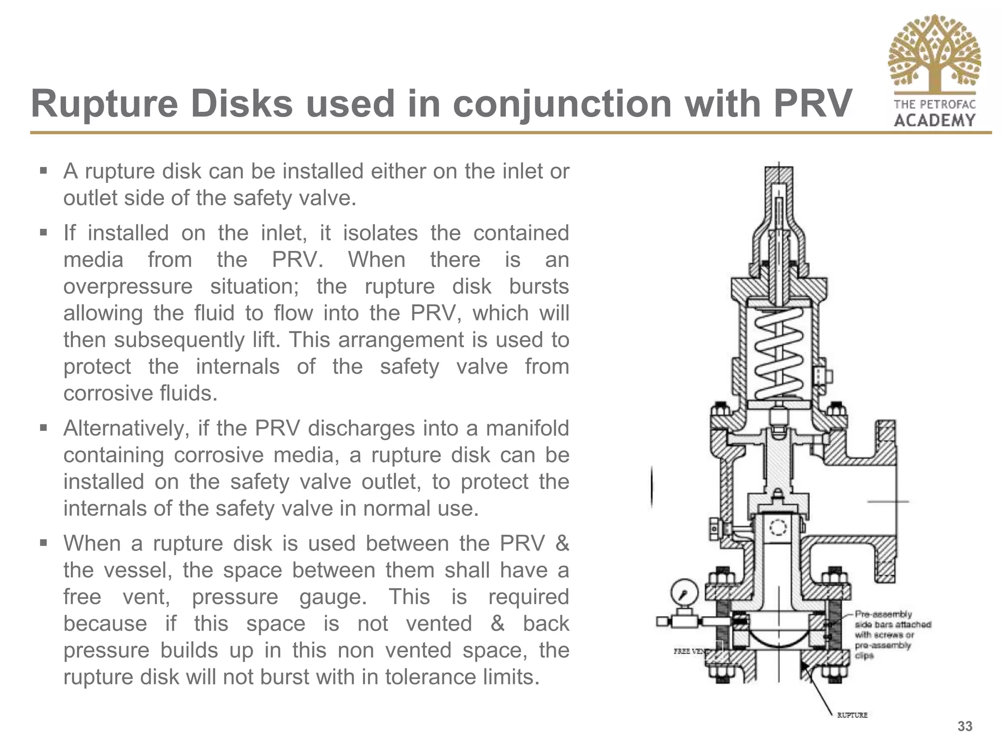
Pressure Relief Devices
Rev. # – Mmm YYYY
2
 Objectives
 Relief Events
 Pressure Relief Devices
 Codes & Standards
 Terminology
 Types of Pressure Relief Valves
 Sizing of Pressure Relief Valves
 Rupture Disks
 Pressure & Vacuum Relief Valves
 Inspection & Shop testing
 Review
Table of Contents
3
Course/Learning Objectives
 To understand what are Relief events and what is the purpose of
Pressure Relief devices.
 To identify the codes & standards used in selection & sizing of Pressure
Relief Devices
 To learn about the terminologies used
 To understand what is Backpressure
 To learn about the types of Pressure Relief Devices
 To learn about the types of pressure relief valves
 To learn how pressure relief valves are sized
 To understand what are Rupture disks and its types
 To understand what are Pressure & Vacuum Relief valves
 To learn about the various testing and inspection requirements.
4
What is a Relief Event?
 Relief event is the process of de-pressurization to prevent excessive
overpressure in a system.
 Following are some of the causes that can produce overpressure in a
system:
• External fire
• Flow from high pressure source
• Heat input from associated equipment
• Pumps and compressors trips
• Ambient heat transfer
• Liquid expansion in pipes and surge
• Blocked outlet
• Instrument Air failure
• Gas Blow by
• Runaway reactions
5
 Key FPSO/Offshore Platform Applications:
 Separation: Inlet Pressure Control, Slug Catcher, Back-Pressure
Control, Thermal Relief, LP/HP Separator, Water Letdown, Vent to
Flare/Vent Relief, Production Choke, Flare Scrubber
 Auxiliary: Surge Control, Pump Recirculation, Gas Lift, Chemical/Water
Injection, Gas to Flare, Safety Relief
 Dehydration: Lean/Rich Glycol Letdown, Level Control, Back-Pressure
Control, Thermal Relief, Pressure Relief
 Compression: Scrubber, Compressor Recycle, Compressor Anti-surge,
Hot Gas Bypass, Wellhead Injection, Gas Injection, Steam Pressure
Control, Lube Oil Temperature Control, Pressure Relief
• Oil and Gas Separation and Treatment
• Gas Compressor Module
• Heat Exchangers
6
• Water Injection Pumps
• Gas Turbine/Power Generation
• Flare Stack
• Dual Fuel Engines
7
8
Answers to Quiz on Pressure Relief
1Q. The highest allowable set pressure of any safety valve is the maximum
allowable working pressure of the vessel being protected. (T/F)
1A. False. Under certain conditions, such as multiple valves, additional
safety valves may be provided set at pressures higher than the MAWP;
however, at least one must be set no higher than MAWP.
2Q. The Design Pressure and the Maximum Allowable Working
Pressure of a vessel are one and the same. (T/F)
2A. False. Design Pressure is a process design term which specifies the
minimum pressure to which the vessel must be designed. The MAWP,
on the other hand, is a mechanical design term. It goes with the
vessel, i.e, it is the pressure on the vessel’s nameplate and stays with
the vessel no matter where the vessel is used. In practice, the two are
often the same, but not necessarily.
9
10
Answers to Quiz on Pressure Relief
3Q. An oversized safety valve can be vulnerable to the phenomenon known
as chatter. (T/F)
3A. True.
4Q. Safety valve chatter in liquid service is potentially more serious than in
vapor service. (T/F)
4A. True. Because of the liquid hammer effect.
11
Answers to Quiz on Pressure Relief
5Q. For operating contingencies, the ASME Code allows the capacity of a
single safety valve to be calculated at 110% of the MAWP. (T/F)
5A. True.
6Q. Under a fire contingency, the vessel is allowed to reach a higher
pressure than under an operating contingency. (T/F)
6A. True. It is allowed to reach 121% of MAWP.
7Q. It is permissible to have a second safety valve on a vessel set at 105%
of the MAWP. (T/F)
7A. True.
8Q. Accumulation means the same as blowdown. (T/F)
8A. False.
12
13
Answers to Quiz on Pressure Relief
9Q. If a single safety valve is present only for fire, it is permissible to set it
at 110% of the MAWP. (T/F)
9A. False. A single safety valve must be set no higher than the MAWP.
Only if it is a second valve for a fire contingency may it be set at 110%
of MAWP.
10Q. If there are two safety valves on a vessel, pressure during discharge is
allowed to reach 116% of the MAWP. (T/F)
10A. True, assuming the second valve is set at 105% of MAWP as permitted
by the code. With 10% accumulation, maximum pressure becomes
110% of 105%, or (rounded) 116%.
14
Answers to Quiz on Pressure Relief
11Q. If a safety valve is to be routinely operated within 10% of its set
pressure, it is advisable to provide a rupture disc beneath the safety
valve to eliminate losses due to “simmering”. (T/F)
11A. False. Rupture discs must not be operated under these conditions
either. The solution is a pilot-operated valve.
12Q. Proper safety valve servicing requires testing each valve in the “as-
received” condition. (T/F)
12A. True. This is the only way to tell whether the valve was operable.
13Q. We should design for the possibility that safety valve discharges
will become ignited. (T/F)
13A. True.
15
Pressure Relief Devices
 A device actuated by inlet static pressure and designed to open during emergency or
abnormal conditions to prevent a rise of internal fluid pressure in excess of a specified
design value. The device also may be designed to prevent excessive internal vacuum.
 The device may be a pressure relief valve, a non-reclosing pressure relief device –
Rupture disc, or a vacuum relief valve.
 It is the final mechanical device to safeguard Over/ Under pressure to prevent Hazard.
 The function of relief devices is to:
• Prevent an overpressure scenario in the plant (equipment / piping)
• Protect equipment & piping (from damage / loss of containment)
• Protect personnel
• Prevent loss of production time
• Prevent an environmental release/De-escalate fire related damage /Prevent loss of
containment
16
Codes & Standards
 API Std 520, Sizing, Selection, and Installation of Pressure-relieving Devices in
Refineries Part I—Sizing and Selection
 API RP 520, Sizing, Selection, and Installation of Pressure-relieving Devices in
Refineries, Part II—Installation
 API Std 521/ISO 23251, Guide for Pressure-relieving and Depressurizing
Systems
 API Std 526, Flanged Steel Pressure Relief Valves
 API Std 527, Seat Tightness of Pressure Relief Valves
 API Std 2000, Venting Atmospheric and Low-pressure Storage Tanks: Non-
refrigerated and Refrigerated
 ASME Boiler and Pressure Vessel Code , Section I—Power Boilers
 ASME Boiler and Pressure Vessel Code, Section VIII—Pressure Vessels,
Division 1
 ASME B31.3 / Petroleum Refinery Piping
 ASME B16.5 / Flanges & Flanged Fittings
 PED-97 23 EC
17
Superimposed Backpressure
 Pressure in discharge header before the valve opens.
 It is the result of pressure in the discharge system coming from other
sources
 It may be constant or variable
18
Built-up Backpressure
 The pressure that develops (builds up) in the discharge header when the
relief valve opens.
19
Classification of Pressure Relief Devices
Pressure Relief Devices
Reclosing Devices Non-reclosing Devices
Direct-load Controlled
Conventional
Pressure Relief
Valve
Balanced Bellow
Pressure Relief
Valve
Pilot-Operated Safety Valve
Snap-acting Modulating
•Rupture Disc
•Function
•Loading
Principle
•*acc. to ASME
Spring Loaded Safety Valves
Pressure &
Vacuum Relief
Valve
20
Conventional Spring Loaded PRV
 Self-actuated spring-loaded PRV.
 Designed to open at a predetermined
pressure and protect a vessel or system
from excess pressure by removing or
relieving fluid from that vessel or
system.
 Basic elements include
• an inlet nozzle connected to the
vessel or system to be protected,
• a movable disc which controls flow
through the nozzle,
• and a spring which controls the
position of the disc.
21
Conventional Spring Loaded PRV
 Advantages
• Most reliable type if properly sized and operated
• Versatile -- can be used in many services
 Disadvantages
• Relieving pressure affected by back pressure
• Susceptible to chatter if built-up back pressure is too high
 Selection Criteria
• The superimposed backpressure is not variable (otherwise the pressure at
which the valve will open will vary)
• Built-up backpressure should not exceed 10 % of the set pressure at 10 %
allowable overpressure.
• When the superimposed backpressure is constant, the spring load may be
reduced to compensate for the superimposed backpressure.
• Material for spring and bonnet shall be suitable for service fluid
22
Balanced Bellow Spring Loaded PRV
 A balanced PRV is a spring-loaded PRV
which incorporates a bellows or other
means of balancing the valve disc to
minimize the effects of backpressure on
the performance characteristics of the
valve.
 A balanced bellows valve is used where
the built up back pressure is too high for
conventional relief valves or where the
superimposed back pressure varies
widely compared to the set pressure.
 For conventional relief valve,
backpressure should not exceed 10% of
the set pressure at 10% allowable
pressure. However, it is possible to get
relief valve with balanced bellows if total
back pressure (superimposed + built-
up) is up till 50% of the set pressure.
23
Balanced Bellow Spring Loaded PRV
 Advantages
• Relieving pressure not affected by back pressure
• Can handle higher built-up back pressure
• Protects spring and guiding surface from corrosion
 Disadvantages
• Bellows susceptible to fatigue/rupture
• Will release flammables/toxics to atmosphere in case of
bellows rupture
• Requires extended venting system for Bonnet vent to
safe location
 Selection Criteria
• Where the total backpressure (superimposed plus built-
up) does not exceed approximately 50 % of the set
pressure.
• Back pressure is within the limit of Bellows Mechanical
limit.
24
Pilot Operated PRV
 A pilot-operated PRV consists of the
main valve, which encloses a floating
unbalanced piston assembly, and an
external pilot.
 The piston is designed to have a larger
area on the top than on the bottom. Up
to the set pressure, the top and bottom
areas are exposed to the same inlet
operating pressure.
 As the operating pressure increases,
the net seating force increases and
tends to make the valve tighter.
 At the set pressure, the pilot vents the
pressure from the top of the piston; the
resulting net force is now upward
causing the piston to lift, and process
flow is established through the main
valve.
 After the overpressure incident, the pilot
will close the vent, and the net force will
cause the piston to reseat.
25
Pilot Operated PRV
26
Types of Pilot Operated PRVs
Snap Acting type or Pop Action type
 The Pop action pilot causes the main valve to
lift fully at Set pressure without overpressure.
This immediate release of pressure provides
extremely high opening and closing forces on
the main valve seat.
Mainly Classified in Two types of Pilot:
Modulating type
 The modulating pilot opens the main valve only
enough to satisfy the required relieving
capacity and can be used in gas, liquid or two-
phase flow applications. In contrast to a pop
action valve, it limits the amount of relieving
fluid to only the amount required to prevent the
pressure from exceeding the allowable
accumulation.
27
Pilot Operated PRV
 Advantages
• Relieving pressure not affected by backpressure
• Can operate at up to 98% of set pressure
• Less susceptible to chatter (some models)
• Zero Leakage
• Reduced loss of inventory for modulating type
• Smaller, lighter valves at higher pressure and/or with larger orifice size
 Disadvantages
• Pilot is susceptible to plugging by fouling fluids, hydrate formation etc.
• Limited chemical and high temperature use due to “O-ring” seals
• Vapor condensation and liquid accumulation above the piston may cause
problems
28
Pilot Operated PRV
 Selection Criteria and Concerns
• When back pressure can not be met by Bellows type
• Very low margin between Max operating pressure and Set pressure
• To optimize line size and reduce inventory loss
• Provide high capacity and one valve can replace multiple conventional valves
• Limited availability of soft goods for seat & seal limits Pilot selection in high
temperature and certain service chemicals
• Not to be used when pilot or pilot line can be choked due to solid particles /
condensates
29
Rupture Disk
 Rupture Disks are used in single & multiple relief
device installations.
 With no moving parts, rupture disks are simple,
reliable & faster acting than other pressure relief
devices. They can be specified for vapor (gas) or liquid
application.
 They are Temperature sensitive devices. Hence
rupture disks must be specified at the Pressure &
temperature the disk is expected to burst.
 Based on the construction, Rupture disks can be
classified into:
• Conventional Disks (Forward acting Rupture disks)
• Reverse Acting (also known as Reverse Buckling disks)
• Composite disks
P&ID symbol
30
Rupture Disk
 Conventional Disks
(Forward acting Rupture disks):
• A forward-acting rupture disk is a formed
(domed), solid metal disk designed to burst at
a rated pressure applied to the concave side.
• The disks in this case bursts in the forward
direction as indicated in the figure.
• These disks perform satisfactorily when the
operating pressures are up to 70% of the
marked burst pressure of the disks.
• If vacuum or backpressure conditions are
present, the disk can be furnished with a
support to prevent reverse flexing.
31
Rupture Disk
 Reverse- Acting Rupture disks:
• A reverse-acting rupture disk is a formed
(domed), solid metal disk designed to reverse
and burst at a rated pressure applied to the
convex side.
• The performance of these disks is satisfactory
when operating pressures are 90% or less of
the marked burst pressure.
• These disks do not require vacuum support.
32
Rupture Disk
 Composite Disks:
• These disks are either flat or dome shaped
multi piece construction disks.
• The dome shaped rupture disks are designed
to burst at rated pressure applied to the
concave side of the disc.
• This type of rupture disk consists of a slotted
metal top section, a metallic or non metallic
bottom seal membrane. Due to the seal
membrane this type of rupture disk offers
better corrosion resistance.
• This type of rupture disk performs
satisfactorily when the operating pressure is
80% or less of the marked burst pressure.
• If vacuum or back pressure condition exists
then a vacuum support is generally provided.
33
Rupture Disks used in conjunction with PRV
 A rupture disk can be installed either on the inlet or
outlet side of the safety valve.
 If installed on the inlet, it isolates the contained
media from the PRV. When there is an
overpressure situation; the rupture disk bursts
allowing the fluid to flow into the PRV, which will
then subsequently lift. This arrangement is used to
protect the internals of the safety valve from
corrosive fluids.
 Alternatively, if the PRV discharges into a manifold
containing corrosive media, a rupture disk can be
installed on the safety valve outlet, to protect the
internals of the safety valve in normal use.
 When a rupture disk is used between the PRV &
the vessel, the space between them shall have a
free vent, pressure gauge. This is required
because if this space is not vented & back
pressure builds up in this non vented space, the
rupture disk will not burst with in tolerance limits.
34
Pressure & Vacuum Relief Valve (PVRV)
 The primary function of PVRV is to protect the tank
from physical damage or permanent deformation
caused by increases in internal pressure or
vacuum encountered in normal operations.
 Pressure / vacuum relief valves are used
extensively on bulk storage tanks, including fixed
roof tanks with floating covers, to minimize
evaporation loss.
 They are used on low pressure storage tanks at
pressures from vacuum through 15 pounds per
square inch gauge (1.034 barg), to prevent the
excessive build up of pressure and vacuum which
can unbalance the system and damage the tanks.
 Pressure and vacuum protection levels are
controlled with springs or weighted pallets and can
be combined to provide the required
pressure/vacuum settings. It is common to
combine pallet and spring systems in one unit i.e.
pressure settings require a spring section, whilst
the vacuum settings use the pallet method.
35
Inspection & Shop Testing
 Inspection and testing for relieving devices shall be as per the following standards.
1. API 526
2. API 527
3. ASME VII, DIV-1
 Following tests are mandatory for ‘UV’ stamped valves as per ASME.
• Hydro test of individual parts as applicable
• Bellows subassembly test
• Set pressure test on fully assembled valve
• Outlet pressure test on fully assembled valve
• Seal leak test on fully assembled valve as per API 527
36
Sizing of Pressure Relief Valves
 Sizing Pressure relief valves involves determining the correct orifice for
the specific valve type to be used to support a required relieving
capacity. The typical method used for sizing pressure relief valves is as
follows:
1. Establish a set pressure at which PRV is to operate based on pressure limits
and applicable vessel code like ASME.
2. Establish various scenarios and determine the required relieving capacity.
Establish all other process parameters.
3. Calculate the discharge area required to relieve the “required relieving
capacity” using the equations based on API520 given on the next slide.
4. With this calculated discharge area, refer the “Orifice Area & Designation”
table in API526 and select higher size of orifice with respect to the
calculated discharge area.
5. Establish valve type required, conventional, bellows, Pilot.
6. Select valve size from vendor catalogues or API 526 tables. Verify rated
capacity in catalogue is higher than required relieving capacity.
• (In step-3, use vendor specific rated coefficient of discharge if vendor is
known)
37
Sizing of Pressure Relief Valves
 For Gas/Vapour Service,
Where,
A= required effective discharge area in mm2
W= required relieving capacity in kg/h
T= Temperature in Kelvin
Z= Compressibility
C= Gas Constant (SI unit)
Kd= Discharge coefficient obtained from the valve manufacturer
P1= Upstream relieving pressure in KPa; this is the set pressure + allowable over pressure+
atmospheric pressure
Kb= Backpressure correction factor, this is applied to valves with bellows only. For
conventional and pilot-operated valves, use a value for Kb equal to 1.0
Kc= is the combination correction factor for installations with a rupture disk upstream of the
PRV); Kc equals 1.0 when a rupture disk is not installed. Kc equals 0.9 when a rupture disk is
installed in combination with a PRV and the combination does not have a certified value.
M= Molecular weight
38
Sizing of Pressure Relief Valves
 For Liquid Service,
Where,
A= required effective discharge area in mm2
Q= flow rate in liters/min
Kd= Discharge coefficient obtained from the valve manufacturer
Kw=Backpressure correction factor, this is applied to valves with bellows only. For
conventional and pilot-operated valves, use a value for Kw equal to 1.0
Kc=combination correction factor for installations with a rupture disk upstream of the PRV); Kc
equals 1.0 when a rupture disk is not installed. Kc equals 0.9 when a rupture disk is installed
in combination with a PRV and the combination does not have a certified value.
Kv= correction factor due to viscosity,
Gl= specific gravity of the liquid at the flowing temperature
P1=upstream relieving pressure, psig (kPag); this is the set pressure plus allowable
overpressure.
P2= total backpressure, psig (kPag).
39
Sizing Pressure Relief Valves

Pressure Vacuum Relief Valve.pptx

  • 1.
  • 2.
    2  Objectives  ReliefEvents  Pressure Relief Devices  Codes & Standards  Terminology  Types of Pressure Relief Valves  Sizing of Pressure Relief Valves  Rupture Disks  Pressure & Vacuum Relief Valves  Inspection & Shop testing  Review Table of Contents
  • 3.
    3 Course/Learning Objectives  Tounderstand what are Relief events and what is the purpose of Pressure Relief devices.  To identify the codes & standards used in selection & sizing of Pressure Relief Devices  To learn about the terminologies used  To understand what is Backpressure  To learn about the types of Pressure Relief Devices  To learn about the types of pressure relief valves  To learn how pressure relief valves are sized  To understand what are Rupture disks and its types  To understand what are Pressure & Vacuum Relief valves  To learn about the various testing and inspection requirements.
  • 4.
    4 What is aRelief Event?  Relief event is the process of de-pressurization to prevent excessive overpressure in a system.  Following are some of the causes that can produce overpressure in a system: • External fire • Flow from high pressure source • Heat input from associated equipment • Pumps and compressors trips • Ambient heat transfer • Liquid expansion in pipes and surge • Blocked outlet • Instrument Air failure • Gas Blow by • Runaway reactions
  • 5.
    5  Key FPSO/OffshorePlatform Applications:  Separation: Inlet Pressure Control, Slug Catcher, Back-Pressure Control, Thermal Relief, LP/HP Separator, Water Letdown, Vent to Flare/Vent Relief, Production Choke, Flare Scrubber  Auxiliary: Surge Control, Pump Recirculation, Gas Lift, Chemical/Water Injection, Gas to Flare, Safety Relief  Dehydration: Lean/Rich Glycol Letdown, Level Control, Back-Pressure Control, Thermal Relief, Pressure Relief  Compression: Scrubber, Compressor Recycle, Compressor Anti-surge, Hot Gas Bypass, Wellhead Injection, Gas Injection, Steam Pressure Control, Lube Oil Temperature Control, Pressure Relief • Oil and Gas Separation and Treatment • Gas Compressor Module • Heat Exchangers
  • 6.
    6 • Water InjectionPumps • Gas Turbine/Power Generation • Flare Stack • Dual Fuel Engines
  • 7.
  • 8.
    8 Answers to Quizon Pressure Relief 1Q. The highest allowable set pressure of any safety valve is the maximum allowable working pressure of the vessel being protected. (T/F) 1A. False. Under certain conditions, such as multiple valves, additional safety valves may be provided set at pressures higher than the MAWP; however, at least one must be set no higher than MAWP. 2Q. The Design Pressure and the Maximum Allowable Working Pressure of a vessel are one and the same. (T/F) 2A. False. Design Pressure is a process design term which specifies the minimum pressure to which the vessel must be designed. The MAWP, on the other hand, is a mechanical design term. It goes with the vessel, i.e, it is the pressure on the vessel’s nameplate and stays with the vessel no matter where the vessel is used. In practice, the two are often the same, but not necessarily.
  • 9.
  • 10.
    10 Answers to Quizon Pressure Relief 3Q. An oversized safety valve can be vulnerable to the phenomenon known as chatter. (T/F) 3A. True. 4Q. Safety valve chatter in liquid service is potentially more serious than in vapor service. (T/F) 4A. True. Because of the liquid hammer effect.
  • 11.
    11 Answers to Quizon Pressure Relief 5Q. For operating contingencies, the ASME Code allows the capacity of a single safety valve to be calculated at 110% of the MAWP. (T/F) 5A. True. 6Q. Under a fire contingency, the vessel is allowed to reach a higher pressure than under an operating contingency. (T/F) 6A. True. It is allowed to reach 121% of MAWP. 7Q. It is permissible to have a second safety valve on a vessel set at 105% of the MAWP. (T/F) 7A. True. 8Q. Accumulation means the same as blowdown. (T/F) 8A. False.
  • 12.
  • 13.
    13 Answers to Quizon Pressure Relief 9Q. If a single safety valve is present only for fire, it is permissible to set it at 110% of the MAWP. (T/F) 9A. False. A single safety valve must be set no higher than the MAWP. Only if it is a second valve for a fire contingency may it be set at 110% of MAWP. 10Q. If there are two safety valves on a vessel, pressure during discharge is allowed to reach 116% of the MAWP. (T/F) 10A. True, assuming the second valve is set at 105% of MAWP as permitted by the code. With 10% accumulation, maximum pressure becomes 110% of 105%, or (rounded) 116%.
  • 14.
    14 Answers to Quizon Pressure Relief 11Q. If a safety valve is to be routinely operated within 10% of its set pressure, it is advisable to provide a rupture disc beneath the safety valve to eliminate losses due to “simmering”. (T/F) 11A. False. Rupture discs must not be operated under these conditions either. The solution is a pilot-operated valve. 12Q. Proper safety valve servicing requires testing each valve in the “as- received” condition. (T/F) 12A. True. This is the only way to tell whether the valve was operable. 13Q. We should design for the possibility that safety valve discharges will become ignited. (T/F) 13A. True.
  • 15.
    15 Pressure Relief Devices A device actuated by inlet static pressure and designed to open during emergency or abnormal conditions to prevent a rise of internal fluid pressure in excess of a specified design value. The device also may be designed to prevent excessive internal vacuum.  The device may be a pressure relief valve, a non-reclosing pressure relief device – Rupture disc, or a vacuum relief valve.  It is the final mechanical device to safeguard Over/ Under pressure to prevent Hazard.  The function of relief devices is to: • Prevent an overpressure scenario in the plant (equipment / piping) • Protect equipment & piping (from damage / loss of containment) • Protect personnel • Prevent loss of production time • Prevent an environmental release/De-escalate fire related damage /Prevent loss of containment
  • 16.
    16 Codes & Standards API Std 520, Sizing, Selection, and Installation of Pressure-relieving Devices in Refineries Part I—Sizing and Selection  API RP 520, Sizing, Selection, and Installation of Pressure-relieving Devices in Refineries, Part II—Installation  API Std 521/ISO 23251, Guide for Pressure-relieving and Depressurizing Systems  API Std 526, Flanged Steel Pressure Relief Valves  API Std 527, Seat Tightness of Pressure Relief Valves  API Std 2000, Venting Atmospheric and Low-pressure Storage Tanks: Non- refrigerated and Refrigerated  ASME Boiler and Pressure Vessel Code , Section I—Power Boilers  ASME Boiler and Pressure Vessel Code, Section VIII—Pressure Vessels, Division 1  ASME B31.3 / Petroleum Refinery Piping  ASME B16.5 / Flanges & Flanged Fittings  PED-97 23 EC
  • 17.
    17 Superimposed Backpressure  Pressurein discharge header before the valve opens.  It is the result of pressure in the discharge system coming from other sources  It may be constant or variable
  • 18.
    18 Built-up Backpressure  Thepressure that develops (builds up) in the discharge header when the relief valve opens.
  • 19.
    19 Classification of PressureRelief Devices Pressure Relief Devices Reclosing Devices Non-reclosing Devices Direct-load Controlled Conventional Pressure Relief Valve Balanced Bellow Pressure Relief Valve Pilot-Operated Safety Valve Snap-acting Modulating •Rupture Disc •Function •Loading Principle •*acc. to ASME Spring Loaded Safety Valves Pressure & Vacuum Relief Valve
  • 20.
    20 Conventional Spring LoadedPRV  Self-actuated spring-loaded PRV.  Designed to open at a predetermined pressure and protect a vessel or system from excess pressure by removing or relieving fluid from that vessel or system.  Basic elements include • an inlet nozzle connected to the vessel or system to be protected, • a movable disc which controls flow through the nozzle, • and a spring which controls the position of the disc.
  • 21.
    21 Conventional Spring LoadedPRV  Advantages • Most reliable type if properly sized and operated • Versatile -- can be used in many services  Disadvantages • Relieving pressure affected by back pressure • Susceptible to chatter if built-up back pressure is too high  Selection Criteria • The superimposed backpressure is not variable (otherwise the pressure at which the valve will open will vary) • Built-up backpressure should not exceed 10 % of the set pressure at 10 % allowable overpressure. • When the superimposed backpressure is constant, the spring load may be reduced to compensate for the superimposed backpressure. • Material for spring and bonnet shall be suitable for service fluid
  • 22.
    22 Balanced Bellow SpringLoaded PRV  A balanced PRV is a spring-loaded PRV which incorporates a bellows or other means of balancing the valve disc to minimize the effects of backpressure on the performance characteristics of the valve.  A balanced bellows valve is used where the built up back pressure is too high for conventional relief valves or where the superimposed back pressure varies widely compared to the set pressure.  For conventional relief valve, backpressure should not exceed 10% of the set pressure at 10% allowable pressure. However, it is possible to get relief valve with balanced bellows if total back pressure (superimposed + built- up) is up till 50% of the set pressure.
  • 23.
    23 Balanced Bellow SpringLoaded PRV  Advantages • Relieving pressure not affected by back pressure • Can handle higher built-up back pressure • Protects spring and guiding surface from corrosion  Disadvantages • Bellows susceptible to fatigue/rupture • Will release flammables/toxics to atmosphere in case of bellows rupture • Requires extended venting system for Bonnet vent to safe location  Selection Criteria • Where the total backpressure (superimposed plus built- up) does not exceed approximately 50 % of the set pressure. • Back pressure is within the limit of Bellows Mechanical limit.
  • 24.
    24 Pilot Operated PRV A pilot-operated PRV consists of the main valve, which encloses a floating unbalanced piston assembly, and an external pilot.  The piston is designed to have a larger area on the top than on the bottom. Up to the set pressure, the top and bottom areas are exposed to the same inlet operating pressure.  As the operating pressure increases, the net seating force increases and tends to make the valve tighter.  At the set pressure, the pilot vents the pressure from the top of the piston; the resulting net force is now upward causing the piston to lift, and process flow is established through the main valve.  After the overpressure incident, the pilot will close the vent, and the net force will cause the piston to reseat.
  • 25.
  • 26.
    26 Types of PilotOperated PRVs Snap Acting type or Pop Action type  The Pop action pilot causes the main valve to lift fully at Set pressure without overpressure. This immediate release of pressure provides extremely high opening and closing forces on the main valve seat. Mainly Classified in Two types of Pilot: Modulating type  The modulating pilot opens the main valve only enough to satisfy the required relieving capacity and can be used in gas, liquid or two- phase flow applications. In contrast to a pop action valve, it limits the amount of relieving fluid to only the amount required to prevent the pressure from exceeding the allowable accumulation.
  • 27.
    27 Pilot Operated PRV Advantages • Relieving pressure not affected by backpressure • Can operate at up to 98% of set pressure • Less susceptible to chatter (some models) • Zero Leakage • Reduced loss of inventory for modulating type • Smaller, lighter valves at higher pressure and/or with larger orifice size  Disadvantages • Pilot is susceptible to plugging by fouling fluids, hydrate formation etc. • Limited chemical and high temperature use due to “O-ring” seals • Vapor condensation and liquid accumulation above the piston may cause problems
  • 28.
    28 Pilot Operated PRV Selection Criteria and Concerns • When back pressure can not be met by Bellows type • Very low margin between Max operating pressure and Set pressure • To optimize line size and reduce inventory loss • Provide high capacity and one valve can replace multiple conventional valves • Limited availability of soft goods for seat & seal limits Pilot selection in high temperature and certain service chemicals • Not to be used when pilot or pilot line can be choked due to solid particles / condensates
  • 29.
    29 Rupture Disk  RuptureDisks are used in single & multiple relief device installations.  With no moving parts, rupture disks are simple, reliable & faster acting than other pressure relief devices. They can be specified for vapor (gas) or liquid application.  They are Temperature sensitive devices. Hence rupture disks must be specified at the Pressure & temperature the disk is expected to burst.  Based on the construction, Rupture disks can be classified into: • Conventional Disks (Forward acting Rupture disks) • Reverse Acting (also known as Reverse Buckling disks) • Composite disks P&ID symbol
  • 30.
    30 Rupture Disk  ConventionalDisks (Forward acting Rupture disks): • A forward-acting rupture disk is a formed (domed), solid metal disk designed to burst at a rated pressure applied to the concave side. • The disks in this case bursts in the forward direction as indicated in the figure. • These disks perform satisfactorily when the operating pressures are up to 70% of the marked burst pressure of the disks. • If vacuum or backpressure conditions are present, the disk can be furnished with a support to prevent reverse flexing.
  • 31.
    31 Rupture Disk  Reverse-Acting Rupture disks: • A reverse-acting rupture disk is a formed (domed), solid metal disk designed to reverse and burst at a rated pressure applied to the convex side. • The performance of these disks is satisfactory when operating pressures are 90% or less of the marked burst pressure. • These disks do not require vacuum support.
  • 32.
    32 Rupture Disk  CompositeDisks: • These disks are either flat or dome shaped multi piece construction disks. • The dome shaped rupture disks are designed to burst at rated pressure applied to the concave side of the disc. • This type of rupture disk consists of a slotted metal top section, a metallic or non metallic bottom seal membrane. Due to the seal membrane this type of rupture disk offers better corrosion resistance. • This type of rupture disk performs satisfactorily when the operating pressure is 80% or less of the marked burst pressure. • If vacuum or back pressure condition exists then a vacuum support is generally provided.
  • 33.
    33 Rupture Disks usedin conjunction with PRV  A rupture disk can be installed either on the inlet or outlet side of the safety valve.  If installed on the inlet, it isolates the contained media from the PRV. When there is an overpressure situation; the rupture disk bursts allowing the fluid to flow into the PRV, which will then subsequently lift. This arrangement is used to protect the internals of the safety valve from corrosive fluids.  Alternatively, if the PRV discharges into a manifold containing corrosive media, a rupture disk can be installed on the safety valve outlet, to protect the internals of the safety valve in normal use.  When a rupture disk is used between the PRV & the vessel, the space between them shall have a free vent, pressure gauge. This is required because if this space is not vented & back pressure builds up in this non vented space, the rupture disk will not burst with in tolerance limits.
  • 34.
    34 Pressure & VacuumRelief Valve (PVRV)  The primary function of PVRV is to protect the tank from physical damage or permanent deformation caused by increases in internal pressure or vacuum encountered in normal operations.  Pressure / vacuum relief valves are used extensively on bulk storage tanks, including fixed roof tanks with floating covers, to minimize evaporation loss.  They are used on low pressure storage tanks at pressures from vacuum through 15 pounds per square inch gauge (1.034 barg), to prevent the excessive build up of pressure and vacuum which can unbalance the system and damage the tanks.  Pressure and vacuum protection levels are controlled with springs or weighted pallets and can be combined to provide the required pressure/vacuum settings. It is common to combine pallet and spring systems in one unit i.e. pressure settings require a spring section, whilst the vacuum settings use the pallet method.
  • 35.
    35 Inspection & ShopTesting  Inspection and testing for relieving devices shall be as per the following standards. 1. API 526 2. API 527 3. ASME VII, DIV-1  Following tests are mandatory for ‘UV’ stamped valves as per ASME. • Hydro test of individual parts as applicable • Bellows subassembly test • Set pressure test on fully assembled valve • Outlet pressure test on fully assembled valve • Seal leak test on fully assembled valve as per API 527
  • 36.
    36 Sizing of PressureRelief Valves  Sizing Pressure relief valves involves determining the correct orifice for the specific valve type to be used to support a required relieving capacity. The typical method used for sizing pressure relief valves is as follows: 1. Establish a set pressure at which PRV is to operate based on pressure limits and applicable vessel code like ASME. 2. Establish various scenarios and determine the required relieving capacity. Establish all other process parameters. 3. Calculate the discharge area required to relieve the “required relieving capacity” using the equations based on API520 given on the next slide. 4. With this calculated discharge area, refer the “Orifice Area & Designation” table in API526 and select higher size of orifice with respect to the calculated discharge area. 5. Establish valve type required, conventional, bellows, Pilot. 6. Select valve size from vendor catalogues or API 526 tables. Verify rated capacity in catalogue is higher than required relieving capacity. • (In step-3, use vendor specific rated coefficient of discharge if vendor is known)
  • 37.
    37 Sizing of PressureRelief Valves  For Gas/Vapour Service, Where, A= required effective discharge area in mm2 W= required relieving capacity in kg/h T= Temperature in Kelvin Z= Compressibility C= Gas Constant (SI unit) Kd= Discharge coefficient obtained from the valve manufacturer P1= Upstream relieving pressure in KPa; this is the set pressure + allowable over pressure+ atmospheric pressure Kb= Backpressure correction factor, this is applied to valves with bellows only. For conventional and pilot-operated valves, use a value for Kb equal to 1.0 Kc= is the combination correction factor for installations with a rupture disk upstream of the PRV); Kc equals 1.0 when a rupture disk is not installed. Kc equals 0.9 when a rupture disk is installed in combination with a PRV and the combination does not have a certified value. M= Molecular weight
  • 38.
    38 Sizing of PressureRelief Valves  For Liquid Service, Where, A= required effective discharge area in mm2 Q= flow rate in liters/min Kd= Discharge coefficient obtained from the valve manufacturer Kw=Backpressure correction factor, this is applied to valves with bellows only. For conventional and pilot-operated valves, use a value for Kw equal to 1.0 Kc=combination correction factor for installations with a rupture disk upstream of the PRV); Kc equals 1.0 when a rupture disk is not installed. Kc equals 0.9 when a rupture disk is installed in combination with a PRV and the combination does not have a certified value. Kv= correction factor due to viscosity, Gl= specific gravity of the liquid at the flowing temperature P1=upstream relieving pressure, psig (kPag); this is the set pressure plus allowable overpressure. P2= total backpressure, psig (kPag).
  • 39.