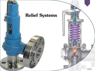
Relief systems
•Download as PPTX, PDF•
5 likes•2,253 views

Relief concept, Pressure Relief systems(PRS), Types of PRS, Their Working Mechanisms and their Installation Procedure along with comparative study.

More Related Content
What's hot
What's hot (20)
Similar to Relief systems
Similar to Relief systems (20)
Recently uploaded
Recently uploaded (20)
Relief systems
- 2. Content • Introduction to Reliefs • Relief Concept • Definitions • Location of Reliefs • Relief Types and Characteristics • Data for Sizing Reliefs • Relief Systems (Relief Installation Practices)
- 3. Introduction to Reliefs • Despite many safety precautions within chemical plants, equipment failures or operator errors can cause increases in process pressures beyond safe levels. • If pressures rise too high, they may exceed the maximum strength of pipelines and vessels. This can result in rupturing of process equipment, causing major releases of toxic or flammable chemicals. • The defense against this type of accident is to prevent the accident in the first place. The second line of defense is better process control. • The third line of defense against excessive pressures is to install relief systems to relieve liquids or gases before excessive pressures are developed. • The relief system is composed of the relief device and the associated downstream process equipment to safely handle the material ejected.
- 4. The method for Safe installation of PRD
- 5. Relief Concept Pressure relief systems are required for the following reasons: • To protect personnel from the dangers of over pressurizing equipment • To minimize chemical losses during pressure upsets • To prevent damage to equipment • To prevent damage to adjoining property • To reduce insurance premiums • To comply with governmental regulations
- 6. Definitions • Set pressure: The pressure at which the relief device begins to activate. • Maximum allowable working pressure (MAWP): The maximum gauge pressure permissible at the top of a vessel for a designated temperature. This is sometimes called the design pressure. Vessel failure typically occurs at 4 or 5 times the • Backpressure: The pressure at the outlet of the relief device during the relief process resulting from pressure in the discharge system. • Blowdown: The pressure difference between the relief set pressure and the relief reseating pressure. It is expressed as a percentage of the set pressure. • Maximum allowable accumulated pressure: The sum of the MAWP and the allowable accumulation. • Relief system: The network of components around a relief device, including the pipe to the relief, the relief device, discharge pipelines, knockout drum, scrubber, flare, or other types of equipment that assist in the safe relief process.
- 7. Contd., • Operating pressure: The gauge pressure during normal service, usually 10% below the MAWP. • Accumulation: The pressure increase over the MAWP of a vessel during the relief process. It is expressed as a percentage of the MAWP. • Overpressure: The pressure increase in the vessel over the set pressure during the relieving process. Overpressure is equivalent to the accumulation when the set pressure is at the MAWP. It is expressed as a percentage of the set pressure.
- 8. Pressure Terminology at a glance • MAWP • Design pressure • Operating pressure • Set pressure • Overpressure • Accumulation • Blowdown
- 9. Location of Reliefs Pressure relief devices are installed at every point identified as potentially hazardous, that is, at points where upset conditions create pressures that may exceed the MAWP. The types of questions asked in this review process are • What happens with loss of cooling, heating, or agitation? • What happens if the process is contaminated or has a mischarge of a catalyst or monomer? • What happens if the operator makes an error? • What is the consequence of closing valves (block valves) on vessels or in lines that are filled with liquids and exposed to heat or refrigeration? • What happens if a line fails, for example, a failure of a high-pressure gas line into a low-pressure vessel? • What happens if the unit operation is engulfed in a fire? • What conditions cause runaway reactions, and how are relief systems designed to handle the discharge as a result of runaway reactions?
- 10. Guidelines for Specifying Relief Positions
- 11. Example • Specify the location of reliefs in the simple polymerization reactor system illustrated in Fig. The major steps in this polymerization process include (1) pumping 100 lb of initiator into reactor R- 1, (2) heating to the reaction temperature of 240°F, (3) adding monomer for a period of 3 hr, and (4) stripping the residual monomer by means of a vacuum using valve V-15. Because the reaction is exothermic, cooling during monomer addition with cooling water is necessary.
- 13. Solution • a. Reactor (R-1): A relief is installed on this reactor because, in general, every process vessel needs a relief. This relief is labeled PSV-1 for pressure safety valve 1. • b. Positive displacement pump (P-1): Positive displacement pumps are overloaded, overheated, and damaged if they are dead-headed without a pressure-relieving device (PSV-2). This type ofrelief discharge is usually recycled back to the feed vessel. • c. Heat exchanger (E-1): Heat exchanger tubes can rupture from excessive pressures when water is blocked in (V-10 and V-11 are closed) and the exchanger is heated (by steam, for example). This hazard is eliminated by adding PSV-3. • d. Drum (D-1): Again, all process vessels need relief valves, PSV-4. • e. Reactor coil: This reactor coil can be pressure-ruptured when water is blocked in (V-4, V-5, V-6, and V-7 are closed) and the coil is heated with steam or even the sun. Add PSV-5 to this coil.
- 15. Relief Types and Characteristics • Specific types of relief devices are chosen for specific applications, such as for liquids, gases, liquids and gases, solids, and corrosive materials; they may be vented to the atmosphere or vented to containment systems (scrubber, flare, condenser, incinerator, and the like). • In engineering terms the type of relief device is specified on the basis of the details of the relief system, process conditions, and physical properties of the relieved fluid. • Spring-Operated Reliefs • Rupture Discs Type • Pilot-Operated Reliefs
- 16. Spring-Operated Reliefs Conventional Type For a conventional relief, the valve opens based on the pressure drop across the valve seat; that is, the set pressure is proportional to the pressure drop across the seat. Thus, if the backpressure downstream of the valve increases, the set pressure will increase and the valve may not open at the correct pressure.
- 17. • For the balanced-bellows design the bellows on the backside of the valve seat ensures that the pressure on that side of the seat is always atmospheric. • Thus the balanced-bellows valve will always open at the desired set pressure. Spring-Operated Reliefs Balanced Bellows Type
- 18. Pros & Cons: Conventional Valve • Advantages + Most reliable type if properly sized and operated + Versatile -- can be used in many services • Disadvantages – Relieving pressure affected by back pressure – Susceptible to chatter if built-up back pressure is too high • Chattering is the rapid opening and closing of a relief valve that can cause valve seat damage or the mechanical failure of the internals.
- 19. Pros & Cons: Balanced Bellows Valve • Advantages + Relieving pressure not affected by back pressure + Can handle higher built-up back pressure + Protects spring from corrosion • Disadvantages – Bellows susceptible to fatigue/rupture – May release flammables/toxics to atmosphere – Requires separate venting system
- 20. Subcategory types of spring-loaded pressure reliefs • 1. The relief valve is primarily for liquid service. The relief valve (liquid only) begins to open at the set pressure. This valve reaches full capacity when the pressure reaches 25% overpressure. The valve closes as the pressure returns to the set pressure. • 2. The safety valve is for gas service. Safety valves pop open when the pressure exceeds the set pressure. This is accomplished by using a discharge nozzle that directs high-velocity material toward the valve seat. After blowdown of the excess pressure, the valve reseats at approximately 4% below the set pressure; the valve has a 4% blowdown. • 3. The safety relief valve is used for liquid and gas service. Safety relief valves function as relief valves for liquids and as safety valves for gases.
- 21. Pilot-Operated Reliefs • The main valve of a pilot-operated relief valve is controlled by a smaller pilot valve that is a spring operated relief valve as shown in Figure • Pilot-operated relief valves are commonly used when a large relieving area at high set pressures is required. • Pilot operated valves are frequently chosen when operating pressures are within 5% of set pressures.
- 22. Rupture Disc Metal Rupture Disc • Rupture discs are frequently installed in series to a spring- loaded relief, a pressure gauge is installed between the two devices. This telltale gauge is an indicator that shows when the disc ruptures.
- 23. Advantages of Rupture Discs • (1) to protect an expensive spring-loaded device from a corrosive environment, • (2) to give absolute isolation when handling extremely toxic chemicals (spring-loaded reliefs may weep), • (3) to give absolute isolation when handling flammable gases, • (4) to protect the relatively complex parts of a spring-loaded device from reactive monomers that could cause plugging, and • (5) to relieve slurries that may plug spring-loaded devices.
- 24. Buckling Pin Relief (Rupture Pin Device) • It is similar to a rupture disc; that is, when the pressure buckles the pin, the valve opens fully. • The major advantage of a buckling-pin relief is that the pin buckles at a precise pressure, and • The major disadvantage of this device is that when the pin buckles, the valve opens and stays open.
- 25. When to Use a Spring-Operated Valve? • Losing entire contents is unacceptable – Fluids above normal boiling point – Toxic fluids • Need to avoid failing low • Return to normal operations quickly • Withstand process pressure changes, including vacuum
- 26. When to Use a Rupture Disc/Pin? • Capital and maintenance savings • Losing the contents is not an issue • Benign service (nontoxic, nonhazardous) • Need for fast-acting device • Potential for relief valve plugging • High viscosity liquids
- 27. Data for Sizing Reliefs • Physical property data and sometimes reaction rate characteristics are required for making relief sizing calculations. • A runaway reaction is another scenario that requires special data. • It is known that runaway reactions nearly always result in two-phase flow reliefs, which are usually more complex. General Code requirements include: – ASME Boiler & Pressure Vessel Codes – ASME B31.3 / Petroleum Refinery Piping – ASME B16.5 / Flanges & Flanged Fittings Relieving pressureshall not exceed MAWP (accumulation) by more than: – 3% for fired and unfired steam boilers – 10% for vessels equipped with a single pressure relief device – 16% for vessels equipped with multiple pressure relief devices – 21% for fire contingency
- 31. References • Chemical Process Safety (Fundamentals with applications), D.A.Crowl & J.F.Louvar, Prentice Hall, New Jersey,(1990). • Safety and Accident Prevention in Chemical Operations, 2nd ed., H. H. Fawcett and W.S. Wood, John Wiley and Sons, New York 1982
- 32. ---ARB