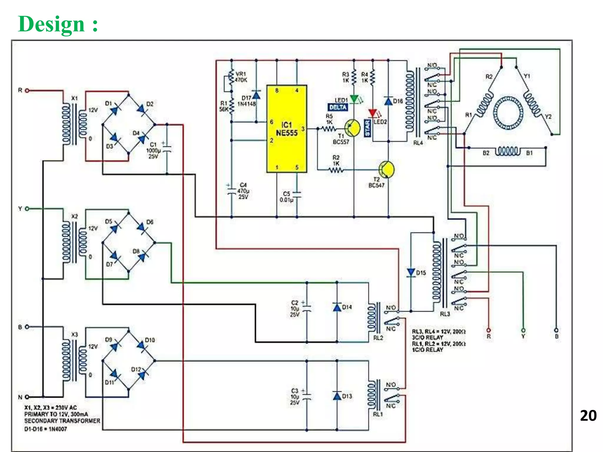
This document describes the design of an automatic star-delta starter for an induction motor using relays and an adjustable electronic timer. The starter is designed to reduce starting current and prevent issues from low voltage, single phasing, over voltage and under voltage. The circuit uses a 555 timer, transistors, diodes, resistors, capacitors, relays and transformers. It operates by starting the motor in a low-current star configuration, then switching to a delta configuration after a set time using relays controlled by the 555 timer. This provides smooth starting of the induction motor.
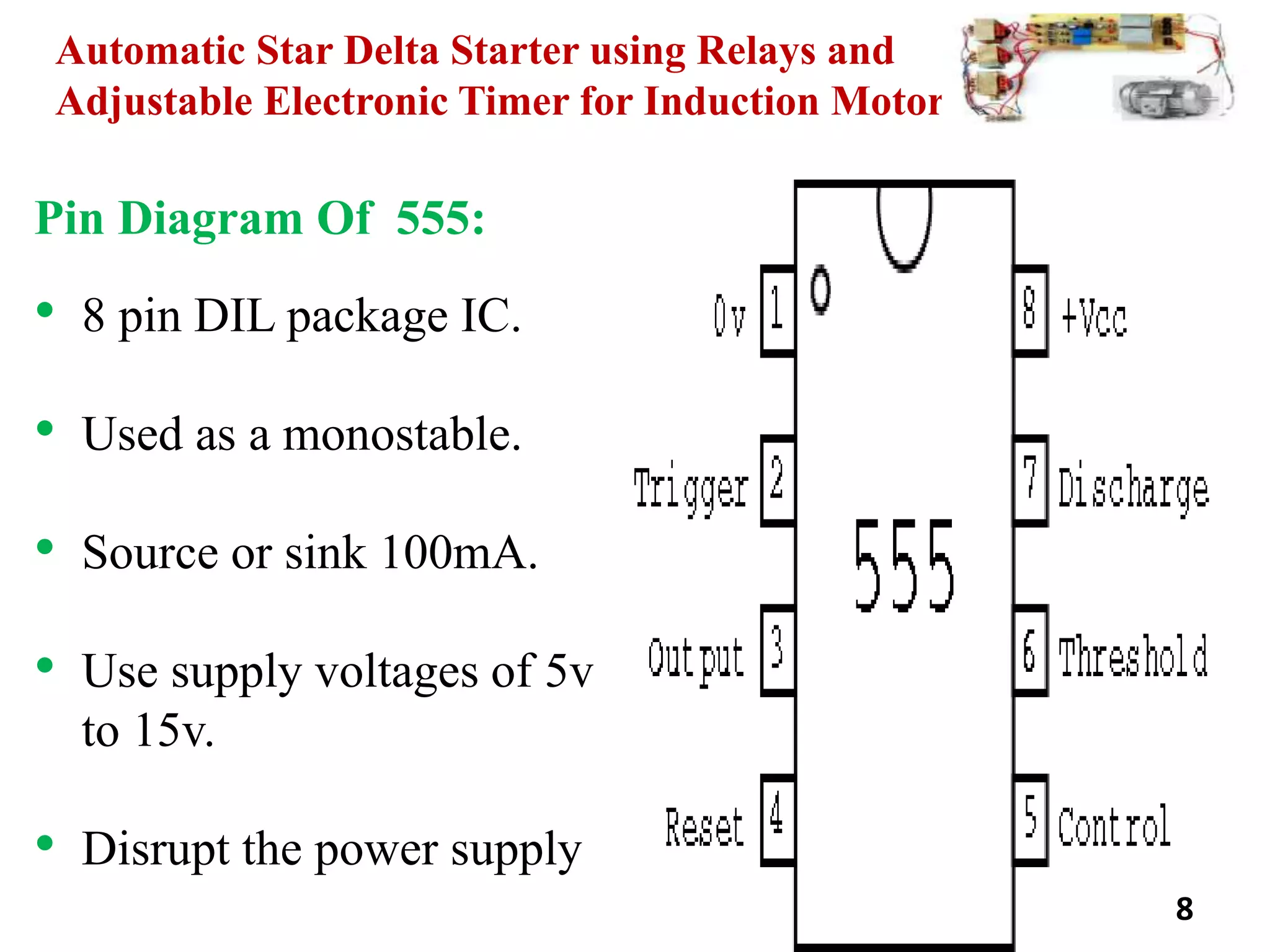
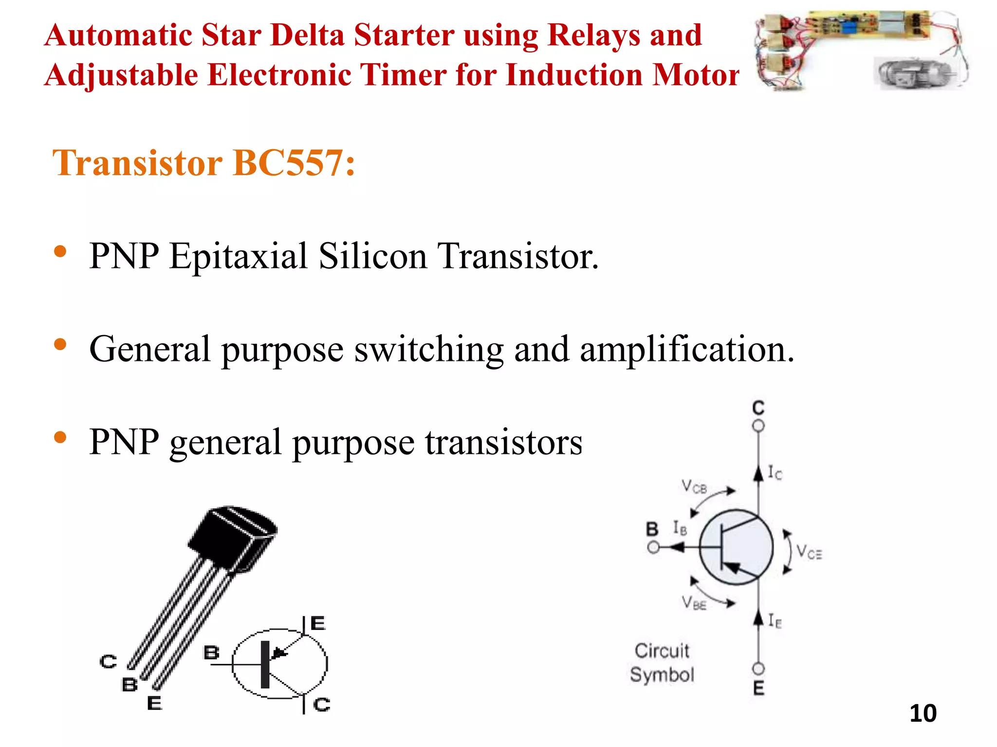
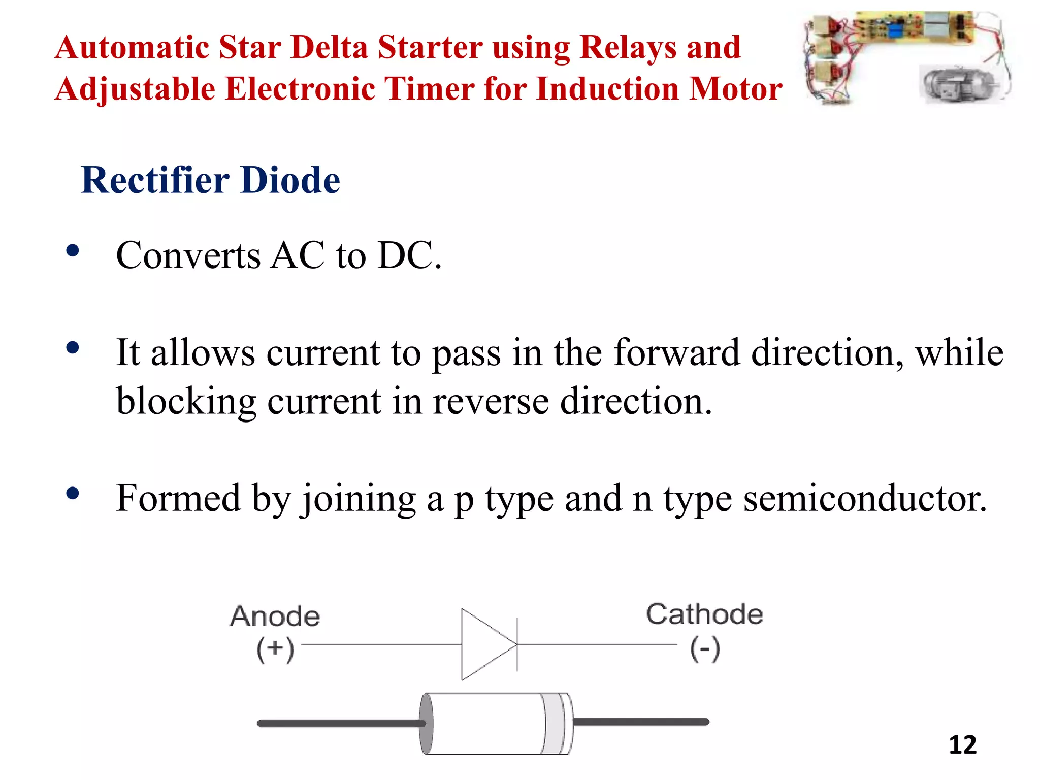
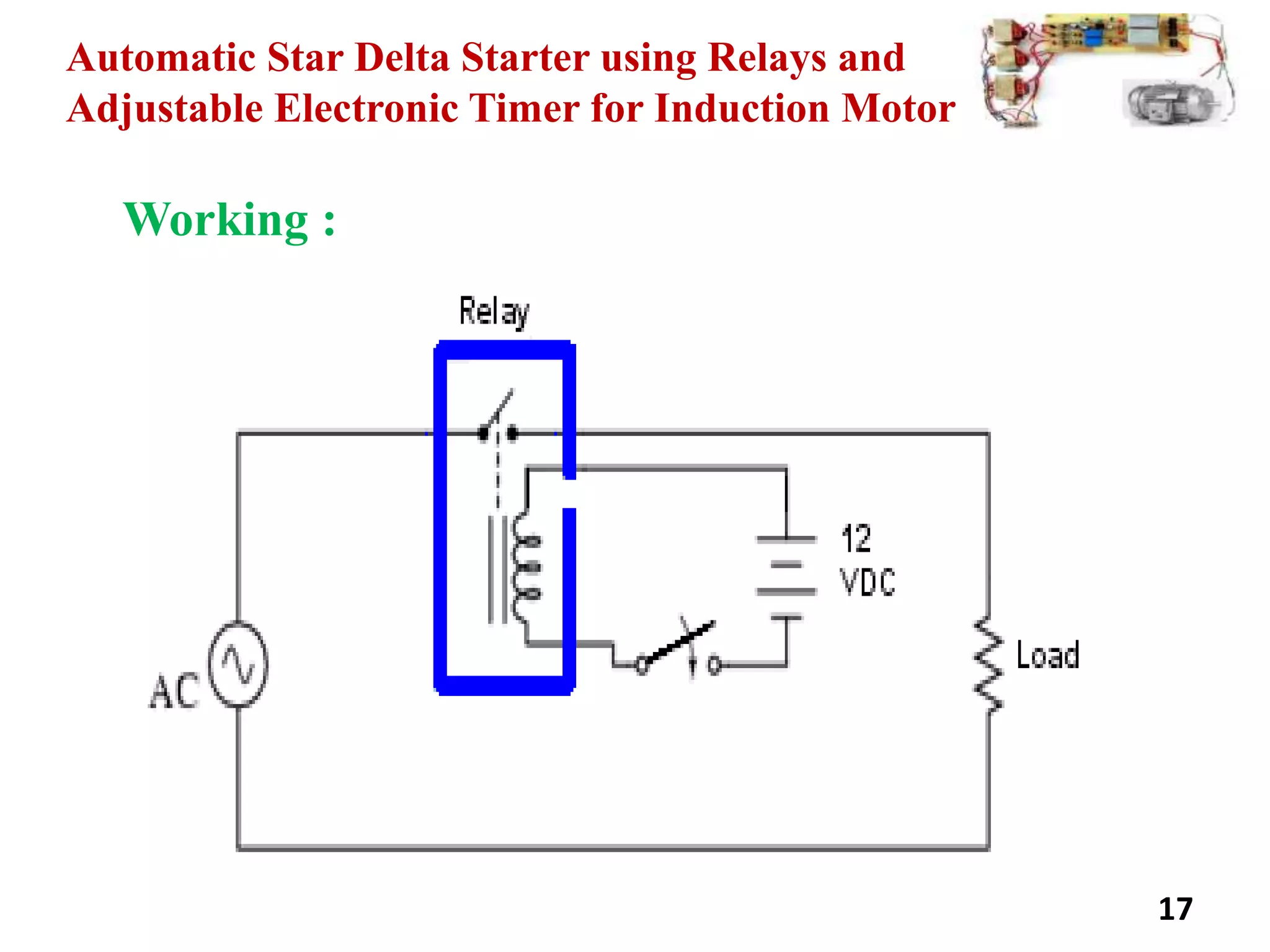
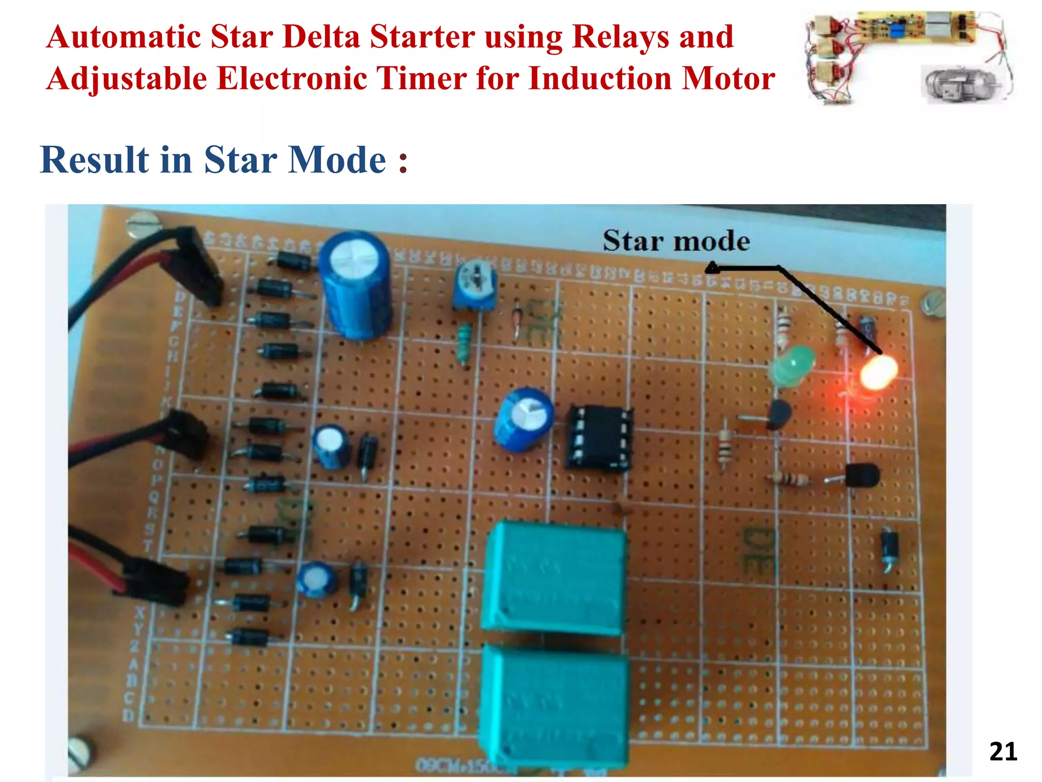
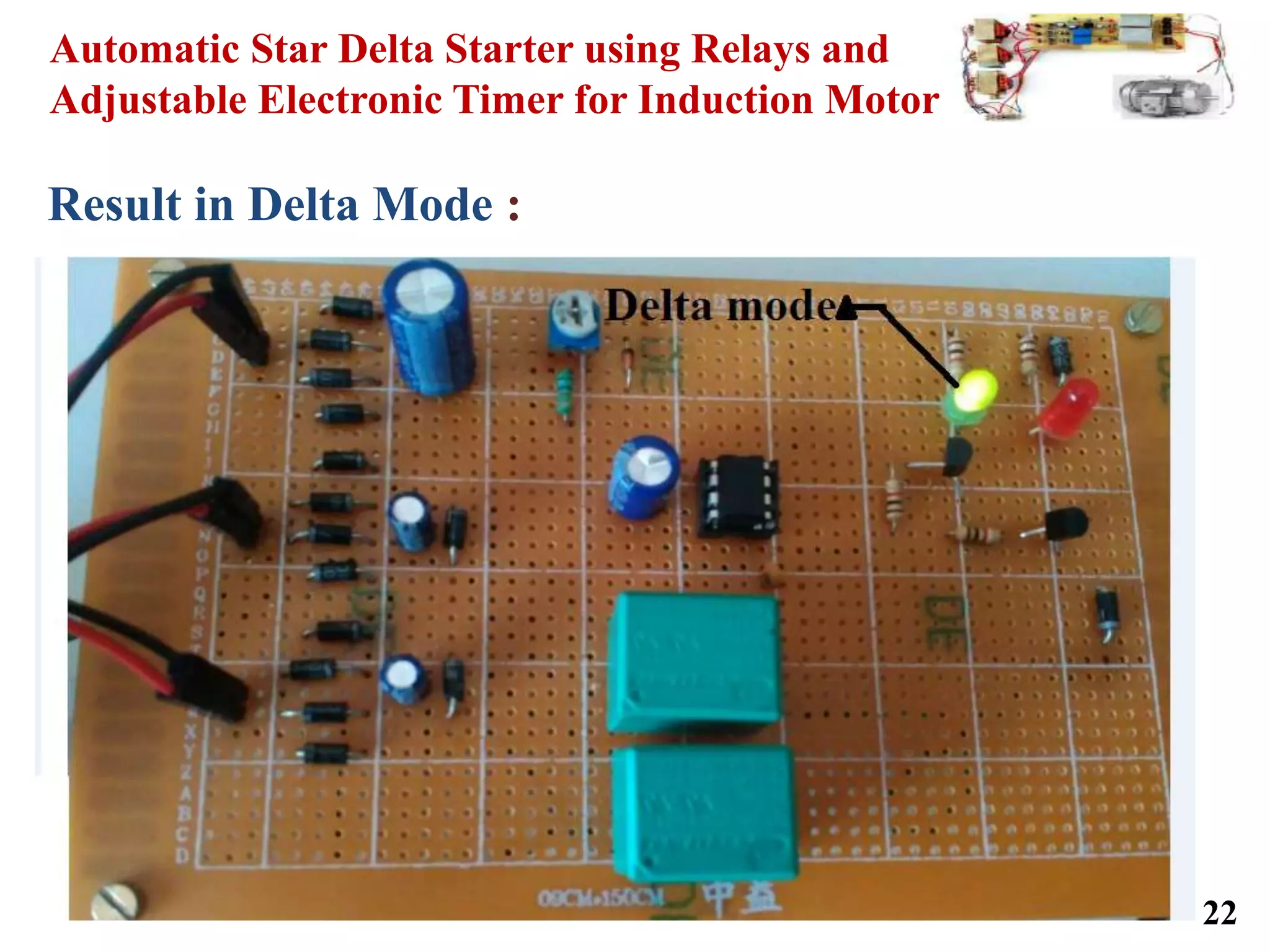
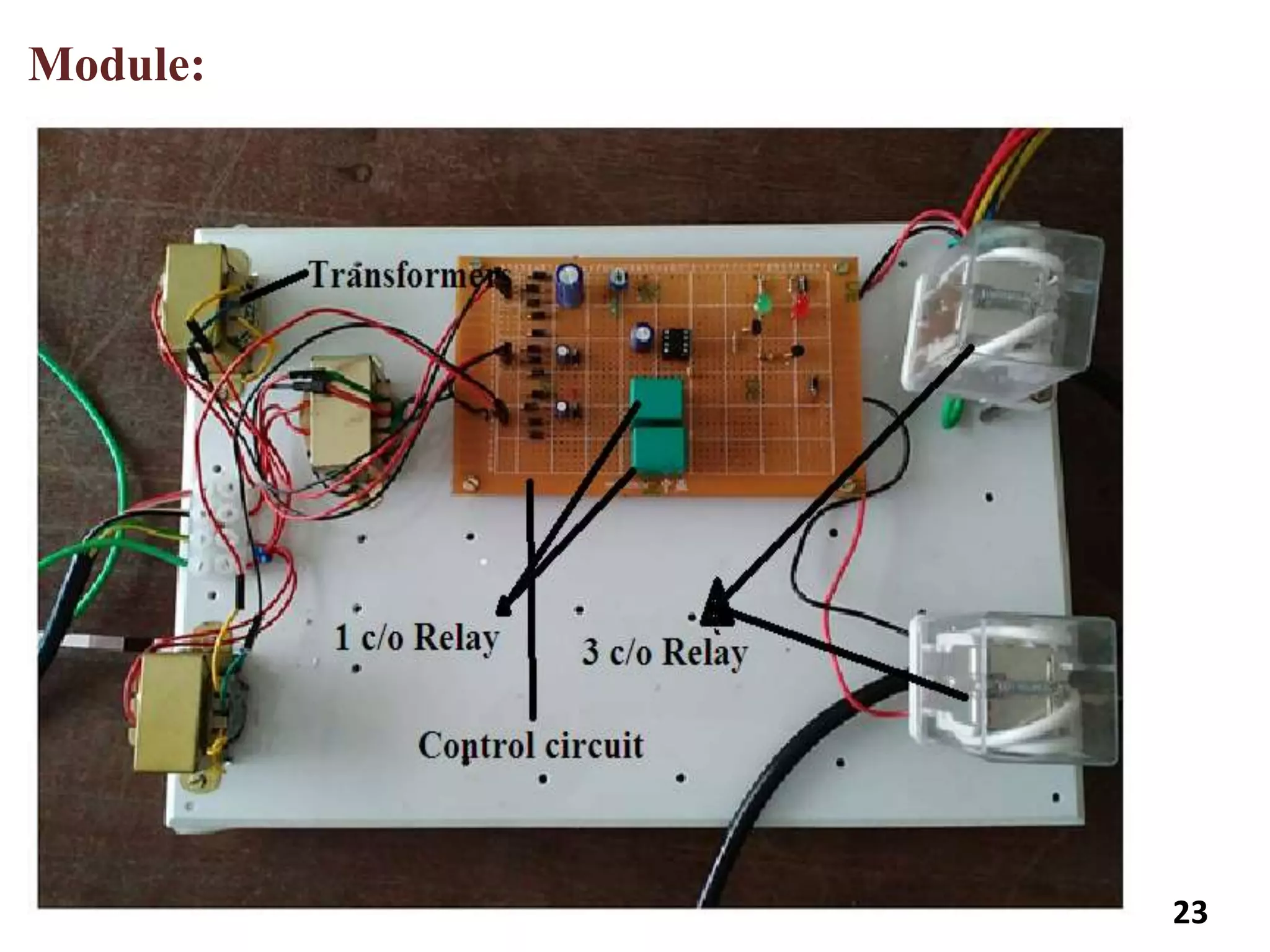
![Automatic Star Delta Starter using Relays and
Adjustable Electronic Timer for Induction Motor
References
• INTERNATIONAL JOURNAL OF SCIENTIFIC &
TECHNOLOGY RESEARCH VOLUME 3, ISSUE 5,
MAY 2014.
• B.L. Theraja and A. K. Theraja, A Text Book of
Electrical Technology. S. Chand Company Ltd. New
Delhi, pp. 851-918, 2001.
• [3]. J.D. Edwards, “Electrical Machines”.
• www.electronicsforu.com 27](https://image.slidesharecdn.com/091656c7-c949-46cb-832f-639cd8863337-150917112330-lva1-app6892/75/Project-PPT-27-2048.jpg)