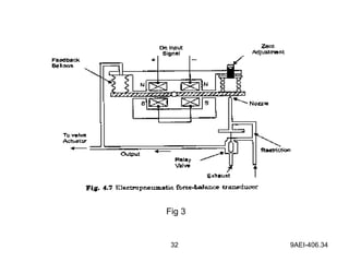
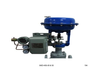
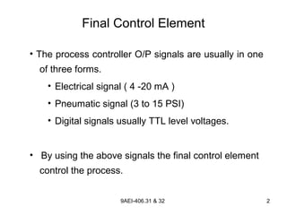
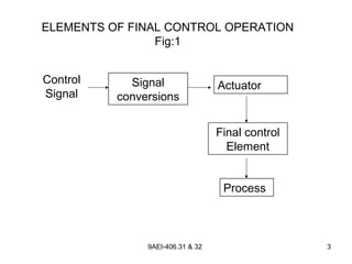
9AEI-406.31 & 32 1
Final Control Element
Basic Principle of Final Control Element
• Final control element operations involve the steps
necessary to convert the control signal, (generated by
a process controller) into proportional action on the
process itself.
9AEI-406.31 & 32 2
Final Control Element
• The process controller O/P signals are usually in one
of three forms.
• Electrical signal ( 4 -20 mA )
• Pneumatic signal (3 to 15 PSI)
• Digital signals usually TTL level voltages.
• By using the above signals the final control element
control the process.
9AEI-406.31 & 32 3
ELEMENTS OF FINAL CONTROL OPERATION
Fig:1
Control
Signal
Signal
conversions
Actuator
Final control
Element
Process
9AEI-406.31 & 32 4
Elements of a Final Control Operation
• Process-control application the conversion of a
process-controller signal to a control function can be
represented by the elements of a final control
operation as shown in fig 1.
9AEI-406.31 & 32 5
Description of each block
1. Control Signal:
The input control signal may take many forms such as
• An electric current
• Pneumatic pressure
• Digital signal etc.,
9AEI-406.31 & 32 6
Description…..
2. Signal conversions :
• This block refers to the modifications that must
be made to the control signal to properly
interface with the next stage of control, that is
actuator.
• Thus, if a valve control element is to be
operated by an electric motor actuator,
• Then a 4 - 20 mA DC control signal must be
modified to operate the motor
9AEI-406.31 & 32 7
Description…..cont..
• If DC motor is used, modification might be current to
voltage conversion and amplification
• Signal conversions are often called transducers
because they convert control signals from one form to
other, such as
• Current to pressure
• Current to voltage
• Analog to digital
9AEI-406.31 & 32 8
Description….
3. Actuators:
• The actuator is a translation of the converted control
signal into action on the control element.
• Thus, if a valve is to operated then the actuator is a
device that converts the control signal into physical
action of opening or closing the valve
9AEI-406.31 & 32 9
Description….
4. Final control element:
• This device has direct influence on the process
dynamic variable and is designed as an integral part of
the process.
• Thus, if flow is to be controlled, then the control
element, a valve, must be built, directly into the flow
system.
• If temperature is to be controlled, then some control
element that has a direct influence on temperature
must be involved in the process.
9AEI-406.31 & 32 10
Description….
4. Final control element:
• This could be a heater / cooler combination, that is
electrically actuated by relays or a pneumatic valve to
control influx of reactants.
9AEI-406.31 & 32 11
Applications of final control element
• To regulate the flow rate in a fluid delivery system.
• To control the degree of backing of crackers in cracking
systems etc.,
• To maintain level, temperature etc., in process industries.
12 9AEI-406.33
Need for E/P and P/E converter
• Signal conversions are often called transducers because
they convert control signals from one form to other, such
as
• Electrical to pressure (E/P)
• Pressure to electrical (P/E)
• The electrical signal in the form of current signal.
13 9AEI-406.33
Need for Current-to-Pressure converter
The P/I converter is used wherever pneumatic signals
must be converted to electronic signals for any one of
the following reasons.
• Transmission over large distances.
• Input to an electronic data logger or computer.
• Input to Telemeter equipment.
• Instrument air not available at the receiver controller.
14 9AEI-406.33
Need for Current-to-Pressure converter
• When we want to use the low level electric current signal
to do work, it is much easier to let the work to be done by
a pneumatic signal.
15 9AEI-406.33
Pressure-to-Current converter
• The pressure-to-current converter, or simply P/I
converter, is complementary to I/P converter.
• In principle, any of the electronics pressure transmitters
could be used, but in practice, special devices are used
to improve accuracy.
16 9AEI-406.33
Pressure-to-Current converter
17 9AEI-406.33
• Because of this need for accuracy, most P/I converters
use a bellows input and a motion balance sensor.
• A typical high quality P/E converter is shown in Fig. 4.8.
The voltage output can be converted into current values
with number of standard circuits.
18 9AEI-406.33
• Bellow is convert the pneumatic control signal (3-15 psi)
in to displacement signal.
• Bellow elongation sensed by LVDT (Linear Variable
Differential Transformer.
19 9AEI-406.33
• The air signals are at low pressure levels (0.2 to 1
Kg/cm2, or 3 psi to 15 psi), and many of the pressure
detectors are not sensitive or not linear enough at these
pressures.
• A P/I converter should be at least 0.5% accurate and
preferably 0.25% to preserve the integrity of the initial
signal.
20 9AEI-406.34
Current-to-Pressure converter
21 9AEI-406.34
• The current-to-pressure converter, or simply I/P
converter, is a very important element in process control.
• The I/P converter gives us a linear way of translating the
4-20 m A current into a 0.2 to 1 Kg/cm2
signal (3 to 15 psi
signal).
22 9AEI-406.34
Current-to-Pressure converter
• There are many designs for these converters, but the
basic principle almost always involves the use of a
flapper/nozzle system.
• Fig. 1 illustrates a simple way to construct such a
converter.
23 9AEI-406.34
Current-to-Pressure converter
Fig 1
24 9AEI-406.34
• The current through a coil produces a force that will tend
to pull the flapper down and close off the gap.
• A high current produces a high pressure so that the
device is direct acting.
25 9AEI-406.34
• Adjustment of the springs and perhaps the position
relative to the pivot to which they are attached allows
the unit to be calibrated so that 4 mA corresponds to 0.2
Kg/cm2 ( or 3 psi) and 20 mA corresponds to 1 kg/cm2
(or 15 psi).
• Fig. 2 illustrates the construction of one such converters
and also lists the various electric devices with which it is
commonly combined.
26 9AEI-406.34
Electro-pneumatic Transmitter
Fig 2
27 9AEI-406.34
• A permanent magnet creates a field that passes through
the steel body of the transmitter and across a small air
gap to the pole piece.
• A multi turn, flexure-mounted voice coil is suspended in
the air gap.
• The input current flows through the coil creating an
electromagnetic force that tend to repel the coil and thus
converts the current signal into a mechanical force.
28 9AEI-406.34
• Since the total force obtainable in a typical voice coil
motor with small current inputs is very less, a different
approach, namely, the use of a reaction nozzle, is
employed here to convert the force into a pneumatic
output pressure.
29 9AEI-406.34
• In this circuit, supply air flows through a restriction and
out the detector nozzle.
• The reaction of the air jet as it impinges against the
nozzle seat supplies the counterbalancing force to the
voice coil motor.
30 9AEI-406.34
• The nozzle back pressure is the transmitted output
pressure.
• In order to make the transmitter insensitive to vibration,
the voice coil is integrally mounted to a float submerged
in silicone oil.
• The float is sized so that its buoyant force equals the
weight of the assembly, leaving a zero net force.
31 9AEI-406.34
• Zero is adjusted by changing a leaf spring force.
• Span is adjusted by turning the range adjusting screw to
change the gap between the screw and the magnet thus
shunting some of the magnetic fielded away from the pole
piece.
• Such converter are called motion balance type converter.
• A force balanced type converter with signal feedback to
improve accuracy is shown in fig.3.
32 9AEI-406.34
Fig 3
9AEI-406.35 33
Actuators
• Actuators converts the control signal into action on the
control elements
Eg:
if a valve is to be operated then the actuator is a device
that converts the control signal into physical action of
opening or closing the valve
9AEI-406.35 34
Actuators…..
• The actuator must provide an accurate output position
proportional to the input signal in spite of various forces
acting on the output member.
• They often translates a control signals into a large force
or torque as required to manipulate some control
element
9AEI-406.35 35
Classification of actuators
Actuators are classified as
• Pneumatic actuators
• Hydraulic actuators
• Electro pneumatic actuators
• Electric motor actuator
9AEI-406.35 36
• Pneumatic actuators may operate directly from the
pneumatic output signal from a pneumatic controller or
they may employ a separate source of compressed air.
• The principle is based on the concept of pressure as
force per unit area.
• It net pressure difference (P2 – P1) is applied to a
diaphragm of surface area A; the net force (F) acting on
it is given as F = (P2 – P1) A.
Pneumatic actuator
9AEI-406.35 37
Pneumatic actuator in low pressure state
Fig.1
9AEI-406.35 38
Pneumatic actuator in high pressure state
Fig.2
9AEI-406.35 39
• Fig. 1 shows the condition in the low signal pressure
state.
• It consists of spring, control shaft and diaphragm.
• The pressure on the opposite side of the diaphragm is
maintained at atmospheric pressure by the open hole H.
• The input pressure applies a force on the diaphragm
9AEI-406.35 40
• It forces the diaphragm and connects the shaft to down
side against the spring force.
• The figure 2 shows the maximum control pressure and
maximum travel of shaft.
• The pressure and force are linearly related.
9AEI-406.35 41
• The shaft position is linearly related to the applied control
pressure
Where
= shaft travel (m)
= applied gauge pressure (Pascals)
A = diaphragm area(m2
)
K = spring constant (N/m2
)
p∆
A
x p
k
∆ = ∆
x∆
9AEI-406.35 42
Advantages
• Low cost
• Simple design
• Mechanical fail safe
• Suitable for high hazardous area
9AEI-406.35 43
Disadvantages
• Slow speed
• Lack of stiffness
• Instability
• Moderate thrust
44 9AEI-406.36
Electro Pneumatic Actuators
• When an electric control systems are employed, it is
often advantageous to use a pneumatic actuator.
• If a suitable air supply is available, a pneumatic actuator
can provide very large power output and may be
operated directly from an electric control system.
• This requires transducing the electrical output of the
controller into an input variable for the actuator.
45 9AEI-406.36
Electric Pneumatic Actuators
• The electro pneumatic pilot is shown in fig (1). It converts
an electrical signal input to a proportional air pressure
output.
• The input electric signal is usually a direct current.
• “Voice coil” motor accepts direct current as input signal.
46 9AEI-406.36
Fig: 1 Electro Pneumatic Pilot
47 9AEI-406.36
Electro Pneumatic Actuators
• The “Voice Coil” motor converts the direct current into a
mechanical force when placed in a magnetic field.
• The force causes a deflection of the balance beam,
covers the nozzle and results in an increase of output
pressure.
48 9AEI-406.36
Electro Pneumatic Actuators
• The output pressure acts on the feedback bellows to
cause a torque on the balance beam equal but
opposite to that of the voice coil.
• The output pressure therefore is proportional to the
input dc current.
• The electro - pneumatic actuator is shown in fig 2.
49 9AEI-406.36
ELECTRO PNEUMATIC ACTUATOR
Fig 2
50 9AEI-406.36
• The motion of the output of the actuator is related to the
balance beam through the feedback lever.
• The output position of the actuator is therefore proportional
to input direct current.
51 9AEI-406.36
Advantages
• Low cost
• Simple design
• Mechanical fail safe
• Suitable for high hazardous area
• Good control with control device
52 9AEI-406.36
Disadvantages
• Slow speed
• Lack of stiffness
• Instability
• Moderate thrust
• Quality air requirement
53 9AEI-406.37
Hydraulic Actuator
• Hydraulic actuator accepts a signal from a pneumatic
controller or an electric controller and employ hydraulic
pressure to drive an output member.
• The hydraulic actuator is used where high speed and
large forces are required.
• The basic principle is shown in figure 3
54 9AEI-406.37
Hydraulic Actuator
• The basic idea is the same as for pneumatic actuators
except that an incompressible fluid is used to provide
the pressure.
• The hydraulic pressure can be made very large by
adjustments of the area of the forcing piston A1.
55 9AEI-406.37
Hydraulic Actuator
Fig 3
56 9AEI-406.37
• The hydraulic pressure is given by
PH = F1 / A1
• Where PH = hydraulic pressure (Pa)
F1 = applied piston force (N)
A1 = forcing piston area (m2
)
579AEI-406.37
• The resulting force on the working piston is
FW = PHA2
Where FW = force of working piston (N)
A2 = working piston area (m2
)
• Thus, the working force is given in terms of the applied
force by
2
1
W
1
A F
F
A
=
58 9AEI-406.37
59 9AEI-406.37
1. Find the working force resulting from 200N applied to a
1cm radius forcing piston
a) If the working piston has a radius of 6cm. Then
b) Find the hydraulic pressure
Example Problem
609AEI-406.37
Solution :
a) We can find the working force from,
2 2
2
1
1
6
. .(200 )
1
w
R Cm
F F N
R Cm
   
= = ÷  ÷
  
FW = 7200N
Example Problem Contd…
2
1
W
1
A F
F
A
=
61 9AEI-406.37
b) Thus, the 200N force provides 7200N of force. The
hydraulic pressure is
W
H -2 2
2
5
H
F 7200N
P = =
A (Π)x(6x10 m)
P =6.4x10 Pa
Example Problem Contd…
62 9AEI-406.37
Advantages
• High thrust
• Fast speed
• High stiffness coefficient
• Self lubrication
63 9AEI-406.37
Disadvantages
• Complex design
• Large heavy structure
• Hazardous
• Fluid viscosity sensitive
9AEI-406.38 64
Solenoid
• A solenoid is an elementary device that converts an
electrical signal into mechanical motion, usually in a
straight line.
9AEI-406.38 65
9AEI-406.38 66
Fig 1
9AEI-406.38 67
• A simple solenoid consists of a coil and plunger as
shown in Fig. 1.
• The plunger may be free standing or spring loaded.
• The coil may be operated by either dc or ac voltage.
9AEI-406.38 68
Specifications
• Solenoid specifications include the electrical rating and
the plunger pull or push force when excited by the
specified voltage.
• Some solenoids are rated only for intermittent duty
because of thermal constraints.
• In this case, the maximum duty cycle ( percentage on
total time) will be specified.
9AEI-406.38 69
Applications
• Solenoids are used when a large sudden force must be
applied to perform some job.
• These actuators are best suited for small, short-stroke
on-off valves, requiring high speeds of response.
• Solenoid-actuated valves can open or close in 8 to 12
milliseconds.
9AEI-406.38 70
• In Fig. 2 a solenoid is used to change the gears of a two-
position transmission.
• An SCR is used to activate the solenoid coil.
9AEI-406.38 71
Fig 2
9AEI-406.38 72
• In many process control pipe lines solenoid values
(where the plunger can act as value stem also) are used
for quick closing or shut-off operations.
• In large pipelines shut-off values are operated with the
help of pneumatic air or hydraulic oil which are in turn
controlled by solenoids valves fitted in the air line or oil
line.
9AEI-406.38 73
• Solenoids move in a straight line and therefore require a
cam or other mechanical converter to operate rotary
values.
9AEI-406.38 74
• A practical solenoid valve consists of the valve body, a
magnetic core attached to the stem and disc, and a
solenoid coil (Refer Fig. 4.11).
• The magnetic core moves in a tube that is closed at the
top and sealed at the bottom, allowing the valve to be
packless.
9AEI-406.38 75
9AEI-406.38 76
• A small spring assists the release and initial closing of
the valve. The valve is electrically energized to open.
• The figure shows both the reenergized and energized
conditions of the valve for better understanding.
9AEI-406.38 77
Disadvantages
• Although the force output of solenoids may not have
many electrical or mechanical limitations, their use as
valve actuators has economic and core (or stem) travel
limitations, and they are expensive too.
9AEI-406.39 78
Stepper Motor
• A stepping motor is a rotating machine that actually
completes a full rotation by sequencing through a series
of discrete rotational seeps.
• Each step position is an equilibrium position in that,
without further excitation, the rotor position will stay at
the latest step.
9AEI-406.39 79
Stepper Motor
• Thus, continuous rotation is achieved by the input of a
train of pulses, each of which causes an advance of one
step.
• It is not really Continuous rotation, but discrete, stepwise
rotation.
• The rotational rate is determined by the number of steps
per revolution and the rates at which the pulses are
applied.
9AEI-406.39 80
9AEI-406.39 81
Stepper motor
Fig.1
9AEI-406.39 82
• The operation of a stepping motor can be understood
from the simple model shown in Figure1,
• Which has 90 per step.
• In this motor, the rotor is a PM that is driven by a
particular set of electromagnets.
• In the position shown, the system is in equilibrium and
no motion occurs.
9AEI-406.39 83
• The switches are typically solid-state devices, such as
transistors, SCRs, or TRICACs.
• The switch sequencer will direct the switches through a
sequence of positions as the pulses are received.
• The next pulse in Figure 2a will change S2 from C to D,
resulting in the poles of that electromagnet reversing
fields.
9AEI-406.39 84
Fig 2
9AEI-406.39 85
• Now, because the pole north/south orientation is
different, the rotor is repelled and attracted so that it
moves to the new position of equilibrium shown in Figure
2b.
• With the next pulse, S1 is changed to B, causing the
same kind of pole reversal and rotation of the PM to a
new position, as shown in Figure 2c.
9AEI-406.39 86
• Finally, the next pulse cause S2 to switch to C again, and
the PM rotor again steps to a new equilibrium position,
as in Figure 2d.
• The next pulse will send the system back to the original
state and the rotor to the original position.
• This sequence is them repeated as the pulse train
comes in, resulting in a stepwise continuous rotation of
the rotor PM.
9AEI-406.39 87
• The most common stepper motor does not use a PM,
but rather a rotor of magnetic material (not a magnet)
with a certain number of teeth.
• This rotor is driven by a phased arrangement of coils
with a different number of poles so that the rotor can
never be in perfect alignment with the stator.
9AEI-406.39 88
9AEI-406.39 89
• Figure 7.26 illustrates this for a rotor with 8 “teeth” and a
stator with 12 “poles.”
• One set of four teeth is aligned, but the other four are
not. If excitation is placed on the next set of poles (B)
and taken off the first set (A), then the rotor will step
once to come into alignment with the B set of poles.
• The direction of rotation of stepper motors can be
changed just by changing the order in which different
poles are activated and deactivated.
9AEI-406.39 90
FIG 7.26
9AEI-406.40 & 41 91
Control Valve
• A valve is a device that regulates the flow of a fluid
(gases, liquids, fluidized solids, or slurries) by opening,
closing, or partially obstructing various passageways.
• Valves are technically pipe fittings,. In an open valve,
fluid flows in a direction from higher pressure to lower
pressure.
9AEI-406.40 & 41 92
9AEI-406.40 & 41 93
• Control valves are valves used to control conditions
such as flow, pressure, temperature, and liquid level by
fully or partially opening or closing in response to signals
received from controllers that compare a "set point" to a
"process variable" whose value is provided by sensors
that monitor changes in such conditions.
9AEI-406.40 & 41 94
• The opening or closing of control valves is done by
means of electrical, hydraulic or pneumatic systems.
• Petitioners are used to control the opening or closing of
the actuator based on Electric, or Pneumatic Signals.
• These control signals, traditionally based on 3-15psi
(0.2-1.0bar), more common now are 4-20mA signals for
industry, 0-10V for HVAC systems.
9AEI-406.40 & 41 95
Construction of control valve
• The control valve is basically divided into three main
parts
• Valve body and Bonnet
• Stem
• plug
9AEI-406.40 & 41 96
1) Body 2) Head 3) Ball 4) Lever handle
5) Stem
9AEI-406.40 & 41 97
Body and bonnet
• The main parts of a valve are the body and the bonnet.
• These two parts form the casing that holds the fluid
going through the valve.
• The bonnet is the casing through which the stem (see
below) passes and that forms a guide and seal for the
stem.
9AEI-406.40 & 41 98
• Valve bodies are usually metallic. Brass, bronze,
gunmetal, cast iron, steel, alloy steels and stainless
steels.
• Seawater applications, like desalination plants, often use
duplex valves, as well as super duplex valves, due to
their corrosion resistant properties, particularly against
warm seawater.
9AEI-406.40 & 41 99
Body materials for various applications
• Alloy 20 valves are typically used in sulphuric acid
plants,
• Monel valves are used in hydrofluoric acid (HF Acid)
plants.
• Hastelloy valves are often used in high temperature
applications, such as nuclear plants,
• Inconel valves are often used in hydrogen applications.
• Plastic bodies are used for relatively low pressures and
temperatures. PVC, PP (Polypropylene), PVDF
(Polyvinylidene fluoride) and glass-reinforced nylon are
common plastics used for valve bodies.
9AEI-406.40 & 41 100
Bonnet
• A bonnet acts as a cover on the valve body.
• It is commonly semi-permanently screwed into the valve
body.
• During manufacture of the valve, the internal parts are
put into the body and then the bonnet is attached to hold
everything together inside.
9AEI-406.40 & 41 101
Ports
• Ports are passages that allow fluid to pass through the
valve.
• Ports are obstructed by the valve member or disc to
control flow.
• Valves most commonly have 2 ports, but may have as
many as 20.
• The valve is almost always connected at it's ports to
pipes or other components.
• Connection methods include threadings, compression
fittings, glue, cement, flanges, or welding
9AEI-406.40 & 41 102
Disc
• A disc or valve member is a movable obstruction inside
the stationary body that adjustably restricts flow through
the valve.
• Although traditionally disc-shaped, discs come in various
shapes.
• A ball is a round valve member with one or more paths
between ports passing through it.
9AEI-406.40 & 41 103
• By rotating the ball flow can be directed between
different ports.
• Ball valves use spherical rotors with a cylindrical hole
drilled as a fluid passage.
• Plug valves use cylindrical or conically tapered rotors
called plugs.
9AEI-406.40 & 41 104
Seat
• The seat is the interior surface of the body which
contacts the disc to form a leak-tight seal.
• In discs that move linearly or swing on a hinge the disc
comes into contact with the seat only when the valve is
shut.
• In disks that rotate, the seat is always in contact with the
disk, but the area of contact changes as the disc is
turned. The seat always remains stationary relative to
the body.
• Seats are classified by whether they are cut directly into
the body, or if they are made of a different material:
9AEI-406.40 & 41 105
• Hard seats are integral to the valve body. Nearly all hard
seated metal valves have a small amount of leakage.
• Examples: Gate, globe, and check valves are usually
hard seated.
• Soft seats are fitted to the valve body and made of
softer materials such as PTFE (Poly tetrafluoroethylene)
or various elastomers such as NBR (Nitrile butadiene
rubber) , EPDM (ethylene propylene diene Monomer (M-class)
rubber), or FKM (Fakultas Kesehatan Masyarakat) depending
on the maximum operating temperature.
• Examples: butterfly, ball, plug, and diaphragm valves are
usually soft seated.
9AEI-406.40 & 41 106106
• Stem is nothing but a vertical metallic shaft or rod.
• The stem transmits motion from controlling device to the
disc.
• The stem typically passes through the bonnet when present.
• The motion transmitted by the stem may be a linear force, a
rotational torque, or some combination of these.
Stem
9AEI-406.40 & 41 107
Gaskets
• The seals or packings used to prevent the escape of a
gas or fluids from valves.
9AEI-406.40 & 41 108
9AEI-406.40 & 41 109
• The valve plug is screwed into stem and then pinned
• It can be a single seated plug or double seated plug
which is guided at the top and bottom
Plug
9AEI-406.40 & 41 110
• According to their basic shapes, plugs can be classified
as
• Disc
• V – shape
• Contoured
Construction of control valve (contd..)
9AEI-406.40 & 41 111
9AEI-406.40 & 41 112
Various Types of valve plugs
9AEI-406.40 & 41 113113
Various plugs
Fig:5
9AEI-406.42 114
Types of control valves
• There are three basic types of control valves whose
relationship between stem position and flow rate
• These are :
• Quick opening control valve
• Linear control valve
• Equal percentage control valve
9AEI-406.42 115
Characteristics of control valves
Fig 1
9AEI-406.42 116
9AEI-406.42 117
Control Valve Flow Characteristics
• The most common characteristics are shown in the
figure above.
• The percent of flow through the valve is plotted against
valve stem position.
• The curves shown are typical of those available from
valve manufacturers.
• These curves are based on constant pressure drop
across the valve and are called inherent flow
characteristics.
9AEI-406.42 118
9AEI-406.42 119
9AEI-406.42 120
Control Valve Flow Characteristics
• Linear - flow capacity increases linearly with valve travel.
• Equal percentage - flow capacity increases
exponentially with valve trim travel. Equal increments of
valve travel produce equal percentage changes in the
existing Cv.
• A modified parabolic characteristic is approximately
midway between linear and equal-percentage
characteristics. It provides fine throttling at low flow
capacity and approximately linear characteristics at
higher flow capacity.
9AEI-406.42 121
• Quick opening provides large changes in flow for very
small changes in lift. It usually has too high a valve gain
for use in modulating control. So it is limited to on-off
service, such as sequential operation in either batch or
semi-continuous processes.
• Hyperbolic
• Square Root
• The majority of control applications are valves with
linear, equal-percentage, or modified-flow characteristics
9AEI-406.42 122
Quick Opening Control Valve
• This type of valve is used predominantly for full on /
full off control applications
• A relatively small motion of valve, for example ,
may allow 90% of maximum flow rate with only a
30% travel of the stem
9AEI-406.42 123
Linear valve
• This type of valve has a flow rate that varies linearly with
the stem position
• It represents the ideal situation where the valve alone
determines the pressure drop
9AEI-406.42 124
Linear valve
• The relationship is expressed as
max max
Q S
=
Q S
Where
Q = flow rate (m3
/s)
Qmax = maximum flow rate (m3
/s)
S = stem position (m)
Smax = maximum stem position (m)
9AEI-406.42 125
Equal percentage valve
• This is a very important type of valve employed in flow
control
• It has a characteristics such that a given percentage
change in stem position produces an equivalent change
in flow , i.e. an equal percentage
9AEI-406.42 126
• Generally, this type of valve does not shut-off the
flow completely in its limits of stem travel
• At the other extreme, the valve allows a maximum
flow Qmax.
Equal percentage valve (contd..)
9AEI-406.42 127
• For this type we define rangeability R as the ratio
R = Qmax/ Qmin
• The curve in fig. 1 shows that increase in flow rate for a
given change in valve opening depends the extent to
which the valve is already open
• This curve typically exponential in form and is
represented by
Q = Qmin .RS/Smax
Equal percentage valve (contd..)
9AEI-406.43 & 44 128
Different Types Of Control Valves
• Globe control valve:
• Sliding Stem Control Valves:
• Lifting Gate Valves
• Rotating-Shaft Control Valves
9AEI-406.43 & 44 129
Sliding Stem Control Valves:
• Control valves in which the plug is operated by means
of reciprocating motion are termed sliding stem valves
and are of following types
1.Single seat plug valves
2.Double seat plug valves.
3.Lifting-gate valves.
9AEI-406.43 & 44 130
Single Seat Control Valve
Fig 1
9AEI-406.43 & 44 131
Single Seat Control Valve
Fig:2, a single seat control valve and pneumatic actuator
9AEI-406.43 & 44 132
Single Seat Control Valve
• Figure 2 is a diagrammatic representation of a single
seat two-port globe valve.
• In this case the fluid flow is pushing against the valve
plug and tending to keep the plug off the valve seat.
9AEI-406.43 & 44 133
Single Seat Control Valve
• The vertical movement of the plug and stem of the
control valve changes the area of opening of the port.
• The flow rate of the fluid passing through the port is
therefore proportioned or throttled by positioning the
valve stem. The stem in turn positioned by the
actuator.
9AEI-406.43 & 44 134
Single seat valve plugs
Fig 3
9AEI-406.43 & 44 135
A few types of single seat valve plugs
• The V-port type plug is open on the inside and the
flow passes horizontally through the triangular
shaped area over the seat ring as in the fig. 3.
9AEI-406.43 & 44 136
Single Seat Plug Valves
• It has the following features:
a)It is simple in construction
b)It can be shut off to provide zero flow.
c)There is a large force acting on the valve stem
because of the differential head acting across the port
and seat area.
9AEI-406.43 & 44 137
Need for Double seat valve
• If a larger valve, having a larger orifice, is used to pass
greater volumes of the medium, then the force that the
actuator must develop in order to close the valve will
also increase.
• Where very large capacities must be passed using large
valves, or where very high differential pressures exist,
the point will be reached where it becomes impractical to
provide sufficient force to close a conventional single
seat valve.
• In such circumstances, the traditional solution to this
problem is the double seat two-port valve.
9AEI-406.43 & 44 138
Single Seat Plug Valves
Fig 4
9AEI-406.43 & 44 139
Double Seat Plug Valve
• The double seat valve has two port openings and
two seats and two plugs.
• The port openings are not usually identical in size
as in fig.4
9AEI-406.43 & 44 140
Single seat valve plugs
Fig 5
9AEI-406.43 & 44 141
Double Seat Plug Valve
This type has the following features.
• Net force acting on the valve stem is generally
small therefore pressure balanced.
• It cannot be shut off tightly because of differential
temperature expansion of value plug and valve
body
9AEI-406.43 & 44 142
Double Seat Plug Valve
• Few types of plugs for single seat and double seat
valves are shown in fig :5
• The piston type plug has one or more grooves along its
length and the flow passes vertically in the grooves
between the plug and seat ring.
9AEI-406.45 143
GATE VALVES
• Gate valves are used when a straight-line flow of fluid
and minimum restric-tion is desired.
• Gate valves are so named because the part that either
stops or allows flow through the valve acts somewhat
like the opening or closing of a gate and is called,
appropriately, the gate.
• The gate is usually wedge shaped.
9AEI-406.45 144
• When the valve is wide open, the gate is fully drawn up
into the valve, leaving an opening for flow through the
valve the same size as the pipe in which the valve is
installed.
• Therefore, there is little pressure drop or flow restriction
through the valve.
9AEI-406.45 145
Fig 1
9AEI-406.45 146
Disadvantages
• Gate valves are not suitable for throttling purposes since
the control of flow would be difficult due to valve design
and since the flow of fluid slapping against a partially
open gate can cause extensive damage to the valve.
9AEI-406.45 147
Lifting Gate Valves
• Lifting gate valves are shown in figure .3
• The gate valve in fig.1 is often used for fluids containing
solid matter, because it presents an open area directly to
the flow of fluid and does not involve a change of
direction of flow stream.
• A gate valve can usually be shut off tightly by wedging
into the seat.
• The chopping action at shut off is very useful for stringy
materials such as paper pulp.
9AEI-406.45 148
9AEI-406.45 149
Fig 3
9AEI-406.45 150
Cross section of Gate valve
9AEI-406.45 151
Weir Valve
• It is also called Diaphragm valves (or) membrane
valves
• The weir valve of fig.5 particularly suited to certain
chemical fluids, because it has a smooth contour inside
the body with no “pockets” for solid matter and because
it has no packing gland around the stem.
9AEI-406.45 152
Weir Valve
• The flexible diaphragm of rubber or other non metallic
material is positioned by the plunger and stem.
• Fluid pressure inside the valve body holds the
diaphragm smoothly against the plunger.
9AEI-406.45 153
Fig 5
9AEI-406.45 154
9AEI-406.45 155
Applications of Diaphragm Valve
• Diaphragm valves can be manual or automated.
• Their application is generally as shut-off valves in
process systems within the food and beverage,
pharmaceutical and biotech industries.
9AEI-406.46 156
Rotating-Shaft Control Valves
• Control valves in which the restriction is accomplished
by the rotation of a plug or vane may be called
rotating-shaft type.
• Rotary type valves, often called quarter-turn valves,
• All require a rotary motion to open and close, and can
easily be fitted with actuators.
9AEI-406.46 157
Classification of Rotary shaft valves
1. Rotating-plug valves
2. Rotating ball valves
3. Butterfly valve
4. Louvers
9AEI-406.46 158
Eccentric plug valves
• Figure 1 shows a typical eccentric plug valve.
• These valves are normally installed with the plug spindle
horizontal as shown, and the attached actuator situated
alongside the valve.
• Plug valves may include linkages between the plug and
actuator.
9AEI-406.46 159
Fig 1
9AEI-406.46 160
Rotating Ball valves
• Figure 2 shows a ball valve consisting of a spherical ball
located between two sealing rings in a simple body form.
• The ball has a hole allowing fluid to pass through. When
aligned with the pipe ends, this gives either full bore or
nearly full bore flow with very little pressure drop.
• Rotating the ball through 90° opens and closes the flow
passage.
• Ball valves designed specifically for control purposes will
have characterized balls or seats, to give a predictable
flow pattern.
9AEI-406.46 161
Fig 2
9AEI-406.46 162
Advantages of ball valves
• Ball valves are an economic means of providing control
with tight shut-off for many fluids including steam at
temperatures up to 250°C (38 bar g, saturated steam).
• Above this temperature, special seat materials or metal-
to-metal seating are necessary, which can be expensive.
• Ball valves are easily actuated and often used for remote
isolation and control.
• For critical control applications, segmented balls and
balls with specially shaped holes are available to provide
different flow characteristics.
9AEI-406.46163
Rotary Plug Valve
• The Rotating plug is shown in fig.3
• The plug is a cylindrical or conical element with a
transverse opening.
9AEI-406.46 164
Rotary Plug Valve
Fig 3
9AEI-406.46 165
Rotary Plug Valve
• It is rotated in the valve body by an external lever so
that the opening on one side of the plug is gradually
covered or uncovered.
• The shape of the opening or port may be circular, V-
shape, rectangular, or any form that is desired to
produce a given flow-angle characteristic.
9AEI-406.46 166
Rotary Plug Valve
• A rotating plug valve having a conical plug can generally
be closed tightly and has high range ability.
• This type of valve is often employed for throttling the flow
of oil to burner systems.
• The valve with a spherical plug that control the flow of
fluid through the valve body is called as ball valve.
Butterfly valves
9AEI-406.47 to 48 167
9AEI-406.47 to 48 168
9AEI-406.47 to 48 169
• The valve is similar in operation to a ball valve.
• Rotating the handle turns the plate either parallel or
perpendicular to the flow of water, shutting off the flow.
9AEI-406.47 to 48 170
Butterfly valves
• Schematic diagram of a butterfly valve, which consists of
a disc rotating in on bearings.
• In the open position the disc is parallel to the pipe wall,
allowing full flow through the valve.
• In the closed position it is rotated against a seat, and
perpendicular to the pipe wall.
9AEI-406.47 to 48 171
• Traditionally, butterfly valves were limited to low
pressures and temperatures, due to the inherent
limitations of the soft seats used.
• Currently, valves with higher temperature seats or high
quality and specially machined metal-to-metal seats are
available to overcome these drawbacks.
• Standard butterfly valves are now used in simple control
applications.
• Particularly in larger sizes and where limited turndown is
required.
9AEI-406.47 to 48 172
• A fluid flowing through a butterfly valve creates a low
pressure drop, in that the valve presents little resistance
to flow when open.
• In general however, their differential pressure limits are
lower than those for globe valves.
• Ball valves are similar except that, due to their different
sealing arrangements, they can operate against higher
differential pressures than equivalent butterfly valves.
9AEI-406.47 to 48 173
9AEI-406.47 to 48 174
Rotation of Disk in butterfly valve
9AEI-406.47 to 48 175
• Butterfly valves are valves with a circular body and a
rotary motion disk closure member which is pivotally
supported by its stem.
• A butterfly valve can appear in various styles, including
eccentric and high-performance valves.
• These are normally a type of valve that uses a flat plate
to control the flow of water.
9AEI-406.47 to 48 176
• As well as this, butterfly valves are used on firefighting
apparatus and typically are used on larger lines, such as
front and rear suction ports and tank to pump lines.
• A butterfly valve is also a type of flow control device,
used to make a fluid start or stop flowing through a
section of pipe.
9AEI-406.47 to 48 177
Butterfly Valve
• The total rotation of the vane is usually restricted to
about 60 degrees, because the addition of 30 deg
does not produce much further increase in flow.
• The V-port butterfly valve incorporates a V-slot in the
body so that rotation of the vane opens a portion of
the V-slot.
• The range ability may vary from 5 to 50 and tight shut
off may be obtained with special design.
9AEI-406.47 to 48 178
9AEI-406.47 to 48 179
9AEI-406.47 to 48 180
Application
• The butterfly valve is most often employed for the control
of air and gas
9AEI-406.47 to 48 181
Louvers
• The louvers consists of two or more rectangular vane
mounted on shafts one above the other and is inter
connected so as to rotate together
• The vanes or operated by an external lever
• In the unirotational louver the vanes remain at all
position
• In a counter rotational louver alternate vanes rotate in
the opposite direction
9AEI-406.47 to 48 182
9AEI-406.47 to 48 183
Louvers
• Flow guide or some time installed between adjacent
vanes in order to improve the effective ness of throttling
• A louver can not provide a tight shut-off because of the
long length of seat surfaces
9AEI-406.47 to 48 184
Application
• Louvers are used exclusively for control of air flow (draft)
at low pressure.
9AEI-406.47 to 48 185
Cross section of louvers
9AEI-406.49 & 50 186
Auto drain valve
• A safety valve is a valve mechanism for the automatic
release of a substance from a boiler, pressure vessel, or
other system when the pressure or temperature exceeds
preset limits.
• It is also called auto drain valve
9AEI-406.49 & 50 187
An oxygen Safety valve
9AEI-406.49 & 50 188
• It is part of a bigger set named pressure safety valves
(PSV) or pressure relief valves (PRV).
• The other parts of the set are named relief valves, safety
relief valves, pilot-operated safety relief valves, low
pressure safety valves, vacuum pressure safety valves.
9AEI-406.49 & 50 189
A cross-section of Proportional safety valve
9AEI-406.49 & 50 190
Safety valve
• A valve that automatically, without using any form of
energy than the liquid in the discharge quantity of liquid,
so as to prevent a predetermined safe pressure is
higher, and closed again to prevent the flow of more
volatile after the normal working pressure were restored.
• The valve can be characterized by a pop-action (quick
opening) or open relationship (not necessarily linear) on
increasing pressure over the whole pressure.
9AEI-406.49 & 50 191
Valve and spring
• A safety valve when the charger through the liquid under
pressure valve plate with mechanical pressure directly,
unlike, for example, a weight, lever and weight or spring.
9AEI-406.49 & 50 192
Applications
• Safety valves were first used on steam boilers during the
industrial revolution.
• Early boilers without them were prone to accidental
explosion.
• In the petroleum refining, petrochemical and chemical
manufacturing, natural gas processing and power
generation industries
9AEI-406.49 & 50 193
Valve Positioner
• The main purpose of having a valve positioner is to
guarantee that the valve does more to the position where
the controller wants it to be.
9AEI-406.49 & 50 194
9AEI-406.49 & 50 195
Need for positioners
• By adding positioner, one can correct for many
variations, including changes in packing friction due to
dirt,
• corrosion, or
• lack of lubrication;
• variations in the dynamic forces of the process;
• sloppy linkages (dead band);
• or non linearities in the valve actuator.
9AEI-406.49 & 50 196
• The effective dead band of a valve/actuator combination
can be as much as 5%;
• With the addition of a positioner it can be reduced to less
than 0.5% .
• It is the job of the positioner to protect the controlled
variable from being upset by any of the variations.
9AEI-406.49 & 50 197
9AEI-406.49 & 50 198
Principle of operation
• In addition, the positioned can be used for spilt ranging
the control signal between more than one valve, for
increasing the actuator speed (by increasing the air
pressure / volume incase of pneumatic actuators) for
modifying the valve characteristics by cams or electronic
function generators.
• But these reasons do not necessitate the use of
positioners as they can be achieved by other means
without using positioned also.
9AEI-406.49 & 50 199
Valve in open loop operation
• When the valve is remote manual (open loop) operation,
it will always benefit from the addition of a positioned,
because it will reduce the valve’s Hysteresis and dead
band while increasing its response.
9AEI-406.49 & 50 200
Valve in Closed loop operation
• When the valve is under automatic (closed loop) control,
the positioner will be helpful when the loop response is
not very fast ( analysis, temperature, liquid level,
blending, slow flow, large volume gas flow etc).
• While the positioner will degrade loop response,
contribute to proportional offsets, and limit cycling in fast
loop (fast flow, liquid pressure, small volume gas
pressure etc).
• Pneumatic actuators without springs always require
valve positioner.
9AEI-406.49 & 50 201
• The valve positioner is a high gain plain proportional
controller which measures the valve stem position,
compares that measurement to its set point (the
controller output signal), and, if there is a difference,
corrects the error.
• The open loop gain of positioners ranges from 10 to 200
(proportional band of 10% to 0.5% ),
• The positioner is a very sensitively tuned proportional
only controller.
9AEI-406.49 & 50 202
Advantages
• Hysteresis is reduced and linearity is usually improved
because the static operation is governed by the feedback
spring and input bellows.
• The actuator can handle much higher static friction forces
because of the amplifying pilot.
• Variable thrust forces on the motor stem do not disturb
the stem position to any great extent.
• Speed of response is generally improved because the
pneumatic controller must only supply sufficient air to fill
the small input bellows rather than the large actuator
chamber.

Process control 3 chapter

  • 1.
    9AEI-406.31 & 321 Final Control Element Basic Principle of Final Control Element • Final control element operations involve the steps necessary to convert the control signal, (generated by a process controller) into proportional action on the process itself.
  • 2.
    9AEI-406.31 & 322 Final Control Element • The process controller O/P signals are usually in one of three forms. • Electrical signal ( 4 -20 mA ) • Pneumatic signal (3 to 15 PSI) • Digital signals usually TTL level voltages. • By using the above signals the final control element control the process.
  • 3.
    9AEI-406.31 & 323 ELEMENTS OF FINAL CONTROL OPERATION Fig:1 Control Signal Signal conversions Actuator Final control Element Process
  • 4.
    9AEI-406.31 & 324 Elements of a Final Control Operation • Process-control application the conversion of a process-controller signal to a control function can be represented by the elements of a final control operation as shown in fig 1.
  • 5.
    9AEI-406.31 & 325 Description of each block 1. Control Signal: The input control signal may take many forms such as • An electric current • Pneumatic pressure • Digital signal etc.,
  • 6.
    9AEI-406.31 & 326 Description….. 2. Signal conversions : • This block refers to the modifications that must be made to the control signal to properly interface with the next stage of control, that is actuator. • Thus, if a valve control element is to be operated by an electric motor actuator, • Then a 4 - 20 mA DC control signal must be modified to operate the motor
  • 7.
    9AEI-406.31 & 327 Description…..cont.. • If DC motor is used, modification might be current to voltage conversion and amplification • Signal conversions are often called transducers because they convert control signals from one form to other, such as • Current to pressure • Current to voltage • Analog to digital
  • 8.
    9AEI-406.31 & 328 Description…. 3. Actuators: • The actuator is a translation of the converted control signal into action on the control element. • Thus, if a valve is to operated then the actuator is a device that converts the control signal into physical action of opening or closing the valve
  • 9.
    9AEI-406.31 & 329 Description…. 4. Final control element: • This device has direct influence on the process dynamic variable and is designed as an integral part of the process. • Thus, if flow is to be controlled, then the control element, a valve, must be built, directly into the flow system. • If temperature is to be controlled, then some control element that has a direct influence on temperature must be involved in the process.
  • 10.
    9AEI-406.31 & 3210 Description…. 4. Final control element: • This could be a heater / cooler combination, that is electrically actuated by relays or a pneumatic valve to control influx of reactants.
  • 11.
    9AEI-406.31 & 3211 Applications of final control element • To regulate the flow rate in a fluid delivery system. • To control the degree of backing of crackers in cracking systems etc., • To maintain level, temperature etc., in process industries.
  • 12.
    12 9AEI-406.33 Need forE/P and P/E converter • Signal conversions are often called transducers because they convert control signals from one form to other, such as • Electrical to pressure (E/P) • Pressure to electrical (P/E) • The electrical signal in the form of current signal.
  • 13.
    13 9AEI-406.33 Need forCurrent-to-Pressure converter The P/I converter is used wherever pneumatic signals must be converted to electronic signals for any one of the following reasons. • Transmission over large distances. • Input to an electronic data logger or computer. • Input to Telemeter equipment. • Instrument air not available at the receiver controller.
  • 14.
    14 9AEI-406.33 Need forCurrent-to-Pressure converter • When we want to use the low level electric current signal to do work, it is much easier to let the work to be done by a pneumatic signal.
  • 15.
    15 9AEI-406.33 Pressure-to-Current converter •The pressure-to-current converter, or simply P/I converter, is complementary to I/P converter. • In principle, any of the electronics pressure transmitters could be used, but in practice, special devices are used to improve accuracy.
  • 16.
  • 17.
    17 9AEI-406.33 • Becauseof this need for accuracy, most P/I converters use a bellows input and a motion balance sensor. • A typical high quality P/E converter is shown in Fig. 4.8. The voltage output can be converted into current values with number of standard circuits.
  • 18.
    18 9AEI-406.33 • Bellowis convert the pneumatic control signal (3-15 psi) in to displacement signal. • Bellow elongation sensed by LVDT (Linear Variable Differential Transformer.
  • 19.
    19 9AEI-406.33 • Theair signals are at low pressure levels (0.2 to 1 Kg/cm2, or 3 psi to 15 psi), and many of the pressure detectors are not sensitive or not linear enough at these pressures. • A P/I converter should be at least 0.5% accurate and preferably 0.25% to preserve the integrity of the initial signal.
  • 20.
  • 21.
    21 9AEI-406.34 • Thecurrent-to-pressure converter, or simply I/P converter, is a very important element in process control. • The I/P converter gives us a linear way of translating the 4-20 m A current into a 0.2 to 1 Kg/cm2 signal (3 to 15 psi signal).
  • 22.
    22 9AEI-406.34 Current-to-Pressure converter •There are many designs for these converters, but the basic principle almost always involves the use of a flapper/nozzle system. • Fig. 1 illustrates a simple way to construct such a converter.
  • 23.
  • 24.
    24 9AEI-406.34 • Thecurrent through a coil produces a force that will tend to pull the flapper down and close off the gap. • A high current produces a high pressure so that the device is direct acting.
  • 25.
    25 9AEI-406.34 • Adjustmentof the springs and perhaps the position relative to the pivot to which they are attached allows the unit to be calibrated so that 4 mA corresponds to 0.2 Kg/cm2 ( or 3 psi) and 20 mA corresponds to 1 kg/cm2 (or 15 psi). • Fig. 2 illustrates the construction of one such converters and also lists the various electric devices with which it is commonly combined.
  • 26.
  • 27.
    27 9AEI-406.34 • Apermanent magnet creates a field that passes through the steel body of the transmitter and across a small air gap to the pole piece. • A multi turn, flexure-mounted voice coil is suspended in the air gap. • The input current flows through the coil creating an electromagnetic force that tend to repel the coil and thus converts the current signal into a mechanical force.
  • 28.
    28 9AEI-406.34 • Sincethe total force obtainable in a typical voice coil motor with small current inputs is very less, a different approach, namely, the use of a reaction nozzle, is employed here to convert the force into a pneumatic output pressure.
  • 29.
    29 9AEI-406.34 • Inthis circuit, supply air flows through a restriction and out the detector nozzle. • The reaction of the air jet as it impinges against the nozzle seat supplies the counterbalancing force to the voice coil motor.
  • 30.
    30 9AEI-406.34 • Thenozzle back pressure is the transmitted output pressure. • In order to make the transmitter insensitive to vibration, the voice coil is integrally mounted to a float submerged in silicone oil. • The float is sized so that its buoyant force equals the weight of the assembly, leaving a zero net force.
  • 31.
    31 9AEI-406.34 • Zerois adjusted by changing a leaf spring force. • Span is adjusted by turning the range adjusting screw to change the gap between the screw and the magnet thus shunting some of the magnetic fielded away from the pole piece. • Such converter are called motion balance type converter. • A force balanced type converter with signal feedback to improve accuracy is shown in fig.3.
  • 32.
  • 33.
    9AEI-406.35 33 Actuators • Actuatorsconverts the control signal into action on the control elements Eg: if a valve is to be operated then the actuator is a device that converts the control signal into physical action of opening or closing the valve
  • 34.
    9AEI-406.35 34 Actuators….. • Theactuator must provide an accurate output position proportional to the input signal in spite of various forces acting on the output member. • They often translates a control signals into a large force or torque as required to manipulate some control element
  • 35.
    9AEI-406.35 35 Classification ofactuators Actuators are classified as • Pneumatic actuators • Hydraulic actuators • Electro pneumatic actuators • Electric motor actuator
  • 36.
    9AEI-406.35 36 • Pneumaticactuators may operate directly from the pneumatic output signal from a pneumatic controller or they may employ a separate source of compressed air. • The principle is based on the concept of pressure as force per unit area. • It net pressure difference (P2 – P1) is applied to a diaphragm of surface area A; the net force (F) acting on it is given as F = (P2 – P1) A. Pneumatic actuator
  • 37.
    9AEI-406.35 37 Pneumatic actuatorin low pressure state Fig.1
  • 38.
    9AEI-406.35 38 Pneumatic actuatorin high pressure state Fig.2
  • 39.
    9AEI-406.35 39 • Fig.1 shows the condition in the low signal pressure state. • It consists of spring, control shaft and diaphragm. • The pressure on the opposite side of the diaphragm is maintained at atmospheric pressure by the open hole H. • The input pressure applies a force on the diaphragm
  • 40.
    9AEI-406.35 40 • Itforces the diaphragm and connects the shaft to down side against the spring force. • The figure 2 shows the maximum control pressure and maximum travel of shaft. • The pressure and force are linearly related.
  • 41.
    9AEI-406.35 41 • Theshaft position is linearly related to the applied control pressure Where = shaft travel (m) = applied gauge pressure (Pascals) A = diaphragm area(m2 ) K = spring constant (N/m2 ) p∆ A x p k ∆ = ∆ x∆
  • 42.
    9AEI-406.35 42 Advantages • Lowcost • Simple design • Mechanical fail safe • Suitable for high hazardous area
  • 43.
    9AEI-406.35 43 Disadvantages • Slowspeed • Lack of stiffness • Instability • Moderate thrust
  • 44.
    44 9AEI-406.36 Electro PneumaticActuators • When an electric control systems are employed, it is often advantageous to use a pneumatic actuator. • If a suitable air supply is available, a pneumatic actuator can provide very large power output and may be operated directly from an electric control system. • This requires transducing the electrical output of the controller into an input variable for the actuator.
  • 45.
    45 9AEI-406.36 Electric PneumaticActuators • The electro pneumatic pilot is shown in fig (1). It converts an electrical signal input to a proportional air pressure output. • The input electric signal is usually a direct current. • “Voice coil” motor accepts direct current as input signal.
  • 46.
    46 9AEI-406.36 Fig: 1Electro Pneumatic Pilot
  • 47.
    47 9AEI-406.36 Electro PneumaticActuators • The “Voice Coil” motor converts the direct current into a mechanical force when placed in a magnetic field. • The force causes a deflection of the balance beam, covers the nozzle and results in an increase of output pressure.
  • 48.
    48 9AEI-406.36 Electro PneumaticActuators • The output pressure acts on the feedback bellows to cause a torque on the balance beam equal but opposite to that of the voice coil. • The output pressure therefore is proportional to the input dc current. • The electro - pneumatic actuator is shown in fig 2.
  • 49.
  • 50.
    50 9AEI-406.36 • Themotion of the output of the actuator is related to the balance beam through the feedback lever. • The output position of the actuator is therefore proportional to input direct current.
  • 51.
    51 9AEI-406.36 Advantages • Lowcost • Simple design • Mechanical fail safe • Suitable for high hazardous area • Good control with control device
  • 52.
    52 9AEI-406.36 Disadvantages • Slowspeed • Lack of stiffness • Instability • Moderate thrust • Quality air requirement
  • 53.
    53 9AEI-406.37 Hydraulic Actuator •Hydraulic actuator accepts a signal from a pneumatic controller or an electric controller and employ hydraulic pressure to drive an output member. • The hydraulic actuator is used where high speed and large forces are required. • The basic principle is shown in figure 3
  • 54.
    54 9AEI-406.37 Hydraulic Actuator •The basic idea is the same as for pneumatic actuators except that an incompressible fluid is used to provide the pressure. • The hydraulic pressure can be made very large by adjustments of the area of the forcing piston A1.
  • 55.
  • 56.
    56 9AEI-406.37 • Thehydraulic pressure is given by PH = F1 / A1 • Where PH = hydraulic pressure (Pa) F1 = applied piston force (N) A1 = forcing piston area (m2 )
  • 57.
    579AEI-406.37 • The resultingforce on the working piston is FW = PHA2 Where FW = force of working piston (N) A2 = working piston area (m2 ) • Thus, the working force is given in terms of the applied force by 2 1 W 1 A F F A =
  • 58.
  • 59.
    59 9AEI-406.37 1. Findthe working force resulting from 200N applied to a 1cm radius forcing piston a) If the working piston has a radius of 6cm. Then b) Find the hydraulic pressure Example Problem
  • 60.
    609AEI-406.37 Solution : a) Wecan find the working force from, 2 2 2 1 1 6 . .(200 ) 1 w R Cm F F N R Cm     = = ÷  ÷    FW = 7200N Example Problem Contd… 2 1 W 1 A F F A =
  • 61.
    61 9AEI-406.37 b) Thus,the 200N force provides 7200N of force. The hydraulic pressure is W H -2 2 2 5 H F 7200N P = = A (Π)x(6x10 m) P =6.4x10 Pa Example Problem Contd…
  • 62.
    62 9AEI-406.37 Advantages • Highthrust • Fast speed • High stiffness coefficient • Self lubrication
  • 63.
    63 9AEI-406.37 Disadvantages • Complexdesign • Large heavy structure • Hazardous • Fluid viscosity sensitive
  • 64.
    9AEI-406.38 64 Solenoid • Asolenoid is an elementary device that converts an electrical signal into mechanical motion, usually in a straight line.
  • 65.
  • 66.
  • 67.
    9AEI-406.38 67 • Asimple solenoid consists of a coil and plunger as shown in Fig. 1. • The plunger may be free standing or spring loaded. • The coil may be operated by either dc or ac voltage.
  • 68.
    9AEI-406.38 68 Specifications • Solenoidspecifications include the electrical rating and the plunger pull or push force when excited by the specified voltage. • Some solenoids are rated only for intermittent duty because of thermal constraints. • In this case, the maximum duty cycle ( percentage on total time) will be specified.
  • 69.
    9AEI-406.38 69 Applications • Solenoidsare used when a large sudden force must be applied to perform some job. • These actuators are best suited for small, short-stroke on-off valves, requiring high speeds of response. • Solenoid-actuated valves can open or close in 8 to 12 milliseconds.
  • 70.
    9AEI-406.38 70 • InFig. 2 a solenoid is used to change the gears of a two- position transmission. • An SCR is used to activate the solenoid coil.
  • 71.
  • 72.
    9AEI-406.38 72 • Inmany process control pipe lines solenoid values (where the plunger can act as value stem also) are used for quick closing or shut-off operations. • In large pipelines shut-off values are operated with the help of pneumatic air or hydraulic oil which are in turn controlled by solenoids valves fitted in the air line or oil line.
  • 73.
    9AEI-406.38 73 • Solenoidsmove in a straight line and therefore require a cam or other mechanical converter to operate rotary values.
  • 74.
    9AEI-406.38 74 • Apractical solenoid valve consists of the valve body, a magnetic core attached to the stem and disc, and a solenoid coil (Refer Fig. 4.11). • The magnetic core moves in a tube that is closed at the top and sealed at the bottom, allowing the valve to be packless.
  • 75.
  • 76.
    9AEI-406.38 76 • Asmall spring assists the release and initial closing of the valve. The valve is electrically energized to open. • The figure shows both the reenergized and energized conditions of the valve for better understanding.
  • 77.
    9AEI-406.38 77 Disadvantages • Althoughthe force output of solenoids may not have many electrical or mechanical limitations, their use as valve actuators has economic and core (or stem) travel limitations, and they are expensive too.
  • 78.
    9AEI-406.39 78 Stepper Motor •A stepping motor is a rotating machine that actually completes a full rotation by sequencing through a series of discrete rotational seeps. • Each step position is an equilibrium position in that, without further excitation, the rotor position will stay at the latest step.
  • 79.
    9AEI-406.39 79 Stepper Motor •Thus, continuous rotation is achieved by the input of a train of pulses, each of which causes an advance of one step. • It is not really Continuous rotation, but discrete, stepwise rotation. • The rotational rate is determined by the number of steps per revolution and the rates at which the pulses are applied.
  • 80.
  • 81.
  • 82.
    9AEI-406.39 82 • Theoperation of a stepping motor can be understood from the simple model shown in Figure1, • Which has 90 per step. • In this motor, the rotor is a PM that is driven by a particular set of electromagnets. • In the position shown, the system is in equilibrium and no motion occurs.
  • 83.
    9AEI-406.39 83 • Theswitches are typically solid-state devices, such as transistors, SCRs, or TRICACs. • The switch sequencer will direct the switches through a sequence of positions as the pulses are received. • The next pulse in Figure 2a will change S2 from C to D, resulting in the poles of that electromagnet reversing fields.
  • 84.
  • 85.
    9AEI-406.39 85 • Now,because the pole north/south orientation is different, the rotor is repelled and attracted so that it moves to the new position of equilibrium shown in Figure 2b. • With the next pulse, S1 is changed to B, causing the same kind of pole reversal and rotation of the PM to a new position, as shown in Figure 2c.
  • 86.
    9AEI-406.39 86 • Finally,the next pulse cause S2 to switch to C again, and the PM rotor again steps to a new equilibrium position, as in Figure 2d. • The next pulse will send the system back to the original state and the rotor to the original position. • This sequence is them repeated as the pulse train comes in, resulting in a stepwise continuous rotation of the rotor PM.
  • 87.
    9AEI-406.39 87 • Themost common stepper motor does not use a PM, but rather a rotor of magnetic material (not a magnet) with a certain number of teeth. • This rotor is driven by a phased arrangement of coils with a different number of poles so that the rotor can never be in perfect alignment with the stator.
  • 88.
  • 89.
    9AEI-406.39 89 • Figure7.26 illustrates this for a rotor with 8 “teeth” and a stator with 12 “poles.” • One set of four teeth is aligned, but the other four are not. If excitation is placed on the next set of poles (B) and taken off the first set (A), then the rotor will step once to come into alignment with the B set of poles. • The direction of rotation of stepper motors can be changed just by changing the order in which different poles are activated and deactivated.
  • 90.
  • 91.
    9AEI-406.40 & 4191 Control Valve • A valve is a device that regulates the flow of a fluid (gases, liquids, fluidized solids, or slurries) by opening, closing, or partially obstructing various passageways. • Valves are technically pipe fittings,. In an open valve, fluid flows in a direction from higher pressure to lower pressure.
  • 92.
  • 93.
    9AEI-406.40 & 4193 • Control valves are valves used to control conditions such as flow, pressure, temperature, and liquid level by fully or partially opening or closing in response to signals received from controllers that compare a "set point" to a "process variable" whose value is provided by sensors that monitor changes in such conditions.
  • 94.
    9AEI-406.40 & 4194 • The opening or closing of control valves is done by means of electrical, hydraulic or pneumatic systems. • Petitioners are used to control the opening or closing of the actuator based on Electric, or Pneumatic Signals. • These control signals, traditionally based on 3-15psi (0.2-1.0bar), more common now are 4-20mA signals for industry, 0-10V for HVAC systems.
  • 95.
    9AEI-406.40 & 4195 Construction of control valve • The control valve is basically divided into three main parts • Valve body and Bonnet • Stem • plug
  • 96.
    9AEI-406.40 & 4196 1) Body 2) Head 3) Ball 4) Lever handle 5) Stem
  • 97.
    9AEI-406.40 & 4197 Body and bonnet • The main parts of a valve are the body and the bonnet. • These two parts form the casing that holds the fluid going through the valve. • The bonnet is the casing through which the stem (see below) passes and that forms a guide and seal for the stem.
  • 98.
    9AEI-406.40 & 4198 • Valve bodies are usually metallic. Brass, bronze, gunmetal, cast iron, steel, alloy steels and stainless steels. • Seawater applications, like desalination plants, often use duplex valves, as well as super duplex valves, due to their corrosion resistant properties, particularly against warm seawater.
  • 99.
    9AEI-406.40 & 4199 Body materials for various applications • Alloy 20 valves are typically used in sulphuric acid plants, • Monel valves are used in hydrofluoric acid (HF Acid) plants. • Hastelloy valves are often used in high temperature applications, such as nuclear plants, • Inconel valves are often used in hydrogen applications. • Plastic bodies are used for relatively low pressures and temperatures. PVC, PP (Polypropylene), PVDF (Polyvinylidene fluoride) and glass-reinforced nylon are common plastics used for valve bodies.
  • 100.
    9AEI-406.40 & 41100 Bonnet • A bonnet acts as a cover on the valve body. • It is commonly semi-permanently screwed into the valve body. • During manufacture of the valve, the internal parts are put into the body and then the bonnet is attached to hold everything together inside.
  • 101.
    9AEI-406.40 & 41101 Ports • Ports are passages that allow fluid to pass through the valve. • Ports are obstructed by the valve member or disc to control flow. • Valves most commonly have 2 ports, but may have as many as 20. • The valve is almost always connected at it's ports to pipes or other components. • Connection methods include threadings, compression fittings, glue, cement, flanges, or welding
  • 102.
    9AEI-406.40 & 41102 Disc • A disc or valve member is a movable obstruction inside the stationary body that adjustably restricts flow through the valve. • Although traditionally disc-shaped, discs come in various shapes. • A ball is a round valve member with one or more paths between ports passing through it.
  • 103.
    9AEI-406.40 & 41103 • By rotating the ball flow can be directed between different ports. • Ball valves use spherical rotors with a cylindrical hole drilled as a fluid passage. • Plug valves use cylindrical or conically tapered rotors called plugs.
  • 104.
    9AEI-406.40 & 41104 Seat • The seat is the interior surface of the body which contacts the disc to form a leak-tight seal. • In discs that move linearly or swing on a hinge the disc comes into contact with the seat only when the valve is shut. • In disks that rotate, the seat is always in contact with the disk, but the area of contact changes as the disc is turned. The seat always remains stationary relative to the body. • Seats are classified by whether they are cut directly into the body, or if they are made of a different material:
  • 105.
    9AEI-406.40 & 41105 • Hard seats are integral to the valve body. Nearly all hard seated metal valves have a small amount of leakage. • Examples: Gate, globe, and check valves are usually hard seated. • Soft seats are fitted to the valve body and made of softer materials such as PTFE (Poly tetrafluoroethylene) or various elastomers such as NBR (Nitrile butadiene rubber) , EPDM (ethylene propylene diene Monomer (M-class) rubber), or FKM (Fakultas Kesehatan Masyarakat) depending on the maximum operating temperature. • Examples: butterfly, ball, plug, and diaphragm valves are usually soft seated.
  • 106.
    9AEI-406.40 & 41106106 • Stem is nothing but a vertical metallic shaft or rod. • The stem transmits motion from controlling device to the disc. • The stem typically passes through the bonnet when present. • The motion transmitted by the stem may be a linear force, a rotational torque, or some combination of these. Stem
  • 107.
    9AEI-406.40 & 41107 Gaskets • The seals or packings used to prevent the escape of a gas or fluids from valves.
  • 108.
  • 109.
    9AEI-406.40 & 41109 • The valve plug is screwed into stem and then pinned • It can be a single seated plug or double seated plug which is guided at the top and bottom Plug
  • 110.
    9AEI-406.40 & 41110 • According to their basic shapes, plugs can be classified as • Disc • V – shape • Contoured Construction of control valve (contd..)
  • 111.
  • 112.
    9AEI-406.40 & 41112 Various Types of valve plugs
  • 113.
    9AEI-406.40 & 41113113 Various plugs Fig:5
  • 114.
    9AEI-406.42 114 Types ofcontrol valves • There are three basic types of control valves whose relationship between stem position and flow rate • These are : • Quick opening control valve • Linear control valve • Equal percentage control valve
  • 115.
  • 116.
  • 117.
    9AEI-406.42 117 Control ValveFlow Characteristics • The most common characteristics are shown in the figure above. • The percent of flow through the valve is plotted against valve stem position. • The curves shown are typical of those available from valve manufacturers. • These curves are based on constant pressure drop across the valve and are called inherent flow characteristics.
  • 118.
  • 119.
  • 120.
    9AEI-406.42 120 Control ValveFlow Characteristics • Linear - flow capacity increases linearly with valve travel. • Equal percentage - flow capacity increases exponentially with valve trim travel. Equal increments of valve travel produce equal percentage changes in the existing Cv. • A modified parabolic characteristic is approximately midway between linear and equal-percentage characteristics. It provides fine throttling at low flow capacity and approximately linear characteristics at higher flow capacity.
  • 121.
    9AEI-406.42 121 • Quickopening provides large changes in flow for very small changes in lift. It usually has too high a valve gain for use in modulating control. So it is limited to on-off service, such as sequential operation in either batch or semi-continuous processes. • Hyperbolic • Square Root • The majority of control applications are valves with linear, equal-percentage, or modified-flow characteristics
  • 122.
    9AEI-406.42 122 Quick OpeningControl Valve • This type of valve is used predominantly for full on / full off control applications • A relatively small motion of valve, for example , may allow 90% of maximum flow rate with only a 30% travel of the stem
  • 123.
    9AEI-406.42 123 Linear valve •This type of valve has a flow rate that varies linearly with the stem position • It represents the ideal situation where the valve alone determines the pressure drop
  • 124.
    9AEI-406.42 124 Linear valve •The relationship is expressed as max max Q S = Q S Where Q = flow rate (m3 /s) Qmax = maximum flow rate (m3 /s) S = stem position (m) Smax = maximum stem position (m)
  • 125.
    9AEI-406.42 125 Equal percentagevalve • This is a very important type of valve employed in flow control • It has a characteristics such that a given percentage change in stem position produces an equivalent change in flow , i.e. an equal percentage
  • 126.
    9AEI-406.42 126 • Generally,this type of valve does not shut-off the flow completely in its limits of stem travel • At the other extreme, the valve allows a maximum flow Qmax. Equal percentage valve (contd..)
  • 127.
    9AEI-406.42 127 • Forthis type we define rangeability R as the ratio R = Qmax/ Qmin • The curve in fig. 1 shows that increase in flow rate for a given change in valve opening depends the extent to which the valve is already open • This curve typically exponential in form and is represented by Q = Qmin .RS/Smax Equal percentage valve (contd..)
  • 128.
    9AEI-406.43 & 44128 Different Types Of Control Valves • Globe control valve: • Sliding Stem Control Valves: • Lifting Gate Valves • Rotating-Shaft Control Valves
  • 129.
    9AEI-406.43 & 44129 Sliding Stem Control Valves: • Control valves in which the plug is operated by means of reciprocating motion are termed sliding stem valves and are of following types 1.Single seat plug valves 2.Double seat plug valves. 3.Lifting-gate valves.
  • 130.
    9AEI-406.43 & 44130 Single Seat Control Valve Fig 1
  • 131.
    9AEI-406.43 & 44131 Single Seat Control Valve Fig:2, a single seat control valve and pneumatic actuator
  • 132.
    9AEI-406.43 & 44132 Single Seat Control Valve • Figure 2 is a diagrammatic representation of a single seat two-port globe valve. • In this case the fluid flow is pushing against the valve plug and tending to keep the plug off the valve seat.
  • 133.
    9AEI-406.43 & 44133 Single Seat Control Valve • The vertical movement of the plug and stem of the control valve changes the area of opening of the port. • The flow rate of the fluid passing through the port is therefore proportioned or throttled by positioning the valve stem. The stem in turn positioned by the actuator.
  • 134.
    9AEI-406.43 & 44134 Single seat valve plugs Fig 3
  • 135.
    9AEI-406.43 & 44135 A few types of single seat valve plugs • The V-port type plug is open on the inside and the flow passes horizontally through the triangular shaped area over the seat ring as in the fig. 3.
  • 136.
    9AEI-406.43 & 44136 Single Seat Plug Valves • It has the following features: a)It is simple in construction b)It can be shut off to provide zero flow. c)There is a large force acting on the valve stem because of the differential head acting across the port and seat area.
  • 137.
    9AEI-406.43 & 44137 Need for Double seat valve • If a larger valve, having a larger orifice, is used to pass greater volumes of the medium, then the force that the actuator must develop in order to close the valve will also increase. • Where very large capacities must be passed using large valves, or where very high differential pressures exist, the point will be reached where it becomes impractical to provide sufficient force to close a conventional single seat valve. • In such circumstances, the traditional solution to this problem is the double seat two-port valve.
  • 138.
    9AEI-406.43 & 44138 Single Seat Plug Valves Fig 4
  • 139.
    9AEI-406.43 & 44139 Double Seat Plug Valve • The double seat valve has two port openings and two seats and two plugs. • The port openings are not usually identical in size as in fig.4
  • 140.
    9AEI-406.43 & 44140 Single seat valve plugs Fig 5
  • 141.
    9AEI-406.43 & 44141 Double Seat Plug Valve This type has the following features. • Net force acting on the valve stem is generally small therefore pressure balanced. • It cannot be shut off tightly because of differential temperature expansion of value plug and valve body
  • 142.
    9AEI-406.43 & 44142 Double Seat Plug Valve • Few types of plugs for single seat and double seat valves are shown in fig :5 • The piston type plug has one or more grooves along its length and the flow passes vertically in the grooves between the plug and seat ring.
  • 143.
    9AEI-406.45 143 GATE VALVES •Gate valves are used when a straight-line flow of fluid and minimum restric-tion is desired. • Gate valves are so named because the part that either stops or allows flow through the valve acts somewhat like the opening or closing of a gate and is called, appropriately, the gate. • The gate is usually wedge shaped.
  • 144.
    9AEI-406.45 144 • Whenthe valve is wide open, the gate is fully drawn up into the valve, leaving an opening for flow through the valve the same size as the pipe in which the valve is installed. • Therefore, there is little pressure drop or flow restriction through the valve.
  • 145.
  • 146.
    9AEI-406.45 146 Disadvantages • Gatevalves are not suitable for throttling purposes since the control of flow would be difficult due to valve design and since the flow of fluid slapping against a partially open gate can cause extensive damage to the valve.
  • 147.
    9AEI-406.45 147 Lifting GateValves • Lifting gate valves are shown in figure .3 • The gate valve in fig.1 is often used for fluids containing solid matter, because it presents an open area directly to the flow of fluid and does not involve a change of direction of flow stream. • A gate valve can usually be shut off tightly by wedging into the seat. • The chopping action at shut off is very useful for stringy materials such as paper pulp.
  • 148.
  • 149.
  • 150.
  • 151.
    9AEI-406.45 151 Weir Valve •It is also called Diaphragm valves (or) membrane valves • The weir valve of fig.5 particularly suited to certain chemical fluids, because it has a smooth contour inside the body with no “pockets” for solid matter and because it has no packing gland around the stem.
  • 152.
    9AEI-406.45 152 Weir Valve •The flexible diaphragm of rubber or other non metallic material is positioned by the plunger and stem. • Fluid pressure inside the valve body holds the diaphragm smoothly against the plunger.
  • 153.
  • 154.
  • 155.
    9AEI-406.45 155 Applications ofDiaphragm Valve • Diaphragm valves can be manual or automated. • Their application is generally as shut-off valves in process systems within the food and beverage, pharmaceutical and biotech industries.
  • 156.
    9AEI-406.46 156 Rotating-Shaft ControlValves • Control valves in which the restriction is accomplished by the rotation of a plug or vane may be called rotating-shaft type. • Rotary type valves, often called quarter-turn valves, • All require a rotary motion to open and close, and can easily be fitted with actuators.
  • 157.
    9AEI-406.46 157 Classification ofRotary shaft valves 1. Rotating-plug valves 2. Rotating ball valves 3. Butterfly valve 4. Louvers
  • 158.
    9AEI-406.46 158 Eccentric plugvalves • Figure 1 shows a typical eccentric plug valve. • These valves are normally installed with the plug spindle horizontal as shown, and the attached actuator situated alongside the valve. • Plug valves may include linkages between the plug and actuator.
  • 159.
  • 160.
    9AEI-406.46 160 Rotating Ballvalves • Figure 2 shows a ball valve consisting of a spherical ball located between two sealing rings in a simple body form. • The ball has a hole allowing fluid to pass through. When aligned with the pipe ends, this gives either full bore or nearly full bore flow with very little pressure drop. • Rotating the ball through 90° opens and closes the flow passage. • Ball valves designed specifically for control purposes will have characterized balls or seats, to give a predictable flow pattern.
  • 161.
  • 162.
    9AEI-406.46 162 Advantages ofball valves • Ball valves are an economic means of providing control with tight shut-off for many fluids including steam at temperatures up to 250°C (38 bar g, saturated steam). • Above this temperature, special seat materials or metal- to-metal seating are necessary, which can be expensive. • Ball valves are easily actuated and often used for remote isolation and control. • For critical control applications, segmented balls and balls with specially shaped holes are available to provide different flow characteristics.
  • 163.
    9AEI-406.46163 Rotary Plug Valve •The Rotating plug is shown in fig.3 • The plug is a cylindrical or conical element with a transverse opening.
  • 164.
  • 165.
    9AEI-406.46 165 Rotary PlugValve • It is rotated in the valve body by an external lever so that the opening on one side of the plug is gradually covered or uncovered. • The shape of the opening or port may be circular, V- shape, rectangular, or any form that is desired to produce a given flow-angle characteristic.
  • 166.
    9AEI-406.46 166 Rotary PlugValve • A rotating plug valve having a conical plug can generally be closed tightly and has high range ability. • This type of valve is often employed for throttling the flow of oil to burner systems. • The valve with a spherical plug that control the flow of fluid through the valve body is called as ball valve.
  • 167.
  • 168.
  • 169.
    9AEI-406.47 to 48169 • The valve is similar in operation to a ball valve. • Rotating the handle turns the plate either parallel or perpendicular to the flow of water, shutting off the flow.
  • 170.
    9AEI-406.47 to 48170 Butterfly valves • Schematic diagram of a butterfly valve, which consists of a disc rotating in on bearings. • In the open position the disc is parallel to the pipe wall, allowing full flow through the valve. • In the closed position it is rotated against a seat, and perpendicular to the pipe wall.
  • 171.
    9AEI-406.47 to 48171 • Traditionally, butterfly valves were limited to low pressures and temperatures, due to the inherent limitations of the soft seats used. • Currently, valves with higher temperature seats or high quality and specially machined metal-to-metal seats are available to overcome these drawbacks. • Standard butterfly valves are now used in simple control applications. • Particularly in larger sizes and where limited turndown is required.
  • 172.
    9AEI-406.47 to 48172 • A fluid flowing through a butterfly valve creates a low pressure drop, in that the valve presents little resistance to flow when open. • In general however, their differential pressure limits are lower than those for globe valves. • Ball valves are similar except that, due to their different sealing arrangements, they can operate against higher differential pressures than equivalent butterfly valves.
  • 173.
  • 174.
    9AEI-406.47 to 48174 Rotation of Disk in butterfly valve
  • 175.
    9AEI-406.47 to 48175 • Butterfly valves are valves with a circular body and a rotary motion disk closure member which is pivotally supported by its stem. • A butterfly valve can appear in various styles, including eccentric and high-performance valves. • These are normally a type of valve that uses a flat plate to control the flow of water.
  • 176.
    9AEI-406.47 to 48176 • As well as this, butterfly valves are used on firefighting apparatus and typically are used on larger lines, such as front and rear suction ports and tank to pump lines. • A butterfly valve is also a type of flow control device, used to make a fluid start or stop flowing through a section of pipe.
  • 177.
    9AEI-406.47 to 48177 Butterfly Valve • The total rotation of the vane is usually restricted to about 60 degrees, because the addition of 30 deg does not produce much further increase in flow. • The V-port butterfly valve incorporates a V-slot in the body so that rotation of the vane opens a portion of the V-slot. • The range ability may vary from 5 to 50 and tight shut off may be obtained with special design.
  • 178.
  • 179.
  • 180.
    9AEI-406.47 to 48180 Application • The butterfly valve is most often employed for the control of air and gas
  • 181.
    9AEI-406.47 to 48181 Louvers • The louvers consists of two or more rectangular vane mounted on shafts one above the other and is inter connected so as to rotate together • The vanes or operated by an external lever • In the unirotational louver the vanes remain at all position • In a counter rotational louver alternate vanes rotate in the opposite direction
  • 182.
  • 183.
    9AEI-406.47 to 48183 Louvers • Flow guide or some time installed between adjacent vanes in order to improve the effective ness of throttling • A louver can not provide a tight shut-off because of the long length of seat surfaces
  • 184.
    9AEI-406.47 to 48184 Application • Louvers are used exclusively for control of air flow (draft) at low pressure.
  • 185.
    9AEI-406.47 to 48185 Cross section of louvers
  • 186.
    9AEI-406.49 & 50186 Auto drain valve • A safety valve is a valve mechanism for the automatic release of a substance from a boiler, pressure vessel, or other system when the pressure or temperature exceeds preset limits. • It is also called auto drain valve
  • 187.
    9AEI-406.49 & 50187 An oxygen Safety valve
  • 188.
    9AEI-406.49 & 50188 • It is part of a bigger set named pressure safety valves (PSV) or pressure relief valves (PRV). • The other parts of the set are named relief valves, safety relief valves, pilot-operated safety relief valves, low pressure safety valves, vacuum pressure safety valves.
  • 189.
    9AEI-406.49 & 50189 A cross-section of Proportional safety valve
  • 190.
    9AEI-406.49 & 50190 Safety valve • A valve that automatically, without using any form of energy than the liquid in the discharge quantity of liquid, so as to prevent a predetermined safe pressure is higher, and closed again to prevent the flow of more volatile after the normal working pressure were restored. • The valve can be characterized by a pop-action (quick opening) or open relationship (not necessarily linear) on increasing pressure over the whole pressure.
  • 191.
    9AEI-406.49 & 50191 Valve and spring • A safety valve when the charger through the liquid under pressure valve plate with mechanical pressure directly, unlike, for example, a weight, lever and weight or spring.
  • 192.
    9AEI-406.49 & 50192 Applications • Safety valves were first used on steam boilers during the industrial revolution. • Early boilers without them were prone to accidental explosion. • In the petroleum refining, petrochemical and chemical manufacturing, natural gas processing and power generation industries
  • 193.
    9AEI-406.49 & 50193 Valve Positioner • The main purpose of having a valve positioner is to guarantee that the valve does more to the position where the controller wants it to be.
  • 194.
  • 195.
    9AEI-406.49 & 50195 Need for positioners • By adding positioner, one can correct for many variations, including changes in packing friction due to dirt, • corrosion, or • lack of lubrication; • variations in the dynamic forces of the process; • sloppy linkages (dead band); • or non linearities in the valve actuator.
  • 196.
    9AEI-406.49 & 50196 • The effective dead band of a valve/actuator combination can be as much as 5%; • With the addition of a positioner it can be reduced to less than 0.5% . • It is the job of the positioner to protect the controlled variable from being upset by any of the variations.
  • 197.
  • 198.
    9AEI-406.49 & 50198 Principle of operation • In addition, the positioned can be used for spilt ranging the control signal between more than one valve, for increasing the actuator speed (by increasing the air pressure / volume incase of pneumatic actuators) for modifying the valve characteristics by cams or electronic function generators. • But these reasons do not necessitate the use of positioners as they can be achieved by other means without using positioned also.
  • 199.
    9AEI-406.49 & 50199 Valve in open loop operation • When the valve is remote manual (open loop) operation, it will always benefit from the addition of a positioned, because it will reduce the valve’s Hysteresis and dead band while increasing its response.
  • 200.
    9AEI-406.49 & 50200 Valve in Closed loop operation • When the valve is under automatic (closed loop) control, the positioner will be helpful when the loop response is not very fast ( analysis, temperature, liquid level, blending, slow flow, large volume gas flow etc). • While the positioner will degrade loop response, contribute to proportional offsets, and limit cycling in fast loop (fast flow, liquid pressure, small volume gas pressure etc). • Pneumatic actuators without springs always require valve positioner.
  • 201.
    9AEI-406.49 & 50201 • The valve positioner is a high gain plain proportional controller which measures the valve stem position, compares that measurement to its set point (the controller output signal), and, if there is a difference, corrects the error. • The open loop gain of positioners ranges from 10 to 200 (proportional band of 10% to 0.5% ), • The positioner is a very sensitively tuned proportional only controller.
  • 202.
    9AEI-406.49 & 50202 Advantages • Hysteresis is reduced and linearity is usually improved because the static operation is governed by the feedback spring and input bellows. • The actuator can handle much higher static friction forces because of the amplifying pilot. • Variable thrust forces on the motor stem do not disturb the stem position to any great extent. • Speed of response is generally improved because the pneumatic controller must only supply sufficient air to fill the small input bellows rather than the large actuator chamber.