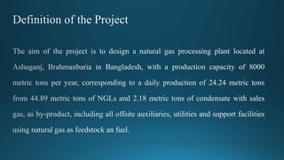
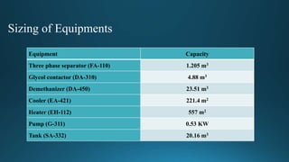
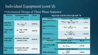
Components Mole fraction Components Mole fraction
Methane 0.9535 n-Nonane 0.0001
Ethane 0.0272 n-Decane 0.0001
Propane 0.0077 C-11 0.0001
i-Butane 0.0018 C-12 0.0001
n-Butane 0.0018 C-13 0.0001
i-Pentane 0.0009 C-14 0.0001
n-Pentane 0.0007 Water 0.0005
n-Hexane 0.0011 Carbon di oxide 0.0016
n-Heptane 0.0005 Nitrogen 0.002
n-Octane 0.0002
• Centrifugal separation
• Gravity settling
• Multistage separation
• Liquid-gas coalescers
Phase Separation
• Flash vaporization
• Fractionation
Condensate
Stabilization
• Refrigeration
• Adsorption by solid
desiccant
• Absorption by
liquid desiccant
Gas dehydration
• Refrigeration
• Lean oil absorption
• Solid bed adsorption
• Membrane separation
NGL recovery
NGL Fractionation yields LPG Economical
 Higher recovery of condensate
 Higher recovery levels of NGL
V-111
EH-112 FA-110
V-311
V-211
EH-312
EH-212
DA-210
DA-310
V-331
G-333
FA-332 EA-330
DA-320
EA-320
EA-421
1 32
54 6
48
11
8
47
9
12
19
20
23 24
21
25 26
28
29
39
31
33
32
30
27
35
G-512
FA-511
46
44
45
53
54
34
40
41
38
7
10
Raw gas
Make up
glycol
Ethane
LPG
Sales gas
Drain
15
18
Flare
FlareFlare
Flare
22
G-321
V-411
EA-410
FA 420
EA-430
FA 440
DA 450
DA 510
C 412
C 413
C 451
G 311
H2O
24
90.04
35
61.23
-9.5
14.29
68.68
15.40
2257
49
55
36
13
50
51
52
14
16
17
37
42
43
56
57
58
List of Equipments
Name of equipment Number of Equipment
Three phase separator 1
Two phase separator 2
Absorber 1
Stripper 1
Distillation column 3
Heat exchanger 4
Heater 3
Cooler 1
Tank 2
Pump 4
Compressor 1
Turbo expander 1
Valve 5
Sizing of Equipments
Equipment Capacity
Three phase separator (FA-110) 1.205 m3
Glycol contactor (DA-310) 4.88 m3
Demethanizer (DA-450) 23.51 m3
Cooler (EA-421) 221.4 m2
Heater (EH-112) 557 m2
Pump (G-311) 0.53 KW
Tank (SA-332) 20.16 m3
Determinant Equation used Result
Determination of vessel diameter
Vertical terminal vapor
velocity, Ut
K×
𝛒 𝐋−𝛒 𝐯
𝛒 𝐯
0.74 ft
Vapor velocity, Uv Uv = 0.75UT 0.56 ft
Vessel internal diameter, D
D = (
𝟒𝐐 𝐯
𝛑𝐔 𝐕
)1/2 +
0.25ft
2.56 ft
Determination of vessel height
Light liquid height, HL Assumed 1ft
Heavy liquid height, HH Assumed 1ft
Height of the light liquid above the
outlet, HR
HR =
𝐐 𝐋𝐋 𝐓 𝐇
𝐀 𝐋 0.75 ft
Liquid height above the settling area
for the light liquid, HA
Assumed 0.5ft
Height above feed nozzle, HD HD min = 24+ 0.5dN 2.5ft
HBN
HBN = 0.5dN + greater
of (2ft or HS + 0.5 ft)
0.85
Vessel shell height, HT
HT = HH + HL + HR +
HA + HBN + HD + 1.5 8.1 ft
Head height, h = 0.64 for r/h=2:1
For mist eliminator, extra height = 1.5 ft
Total height of the vessel = 9.38 ft
Elements Equation/condition
used
Result
Inlet feed
nozzle, dN
dN ≥ (
𝟒 𝐐 𝐦 𝛒 𝐌
𝟔𝟎𝛑
)
1/2 6.065 in
Vapor outlet
pipe
𝛒 𝐠 × 𝐕𝐠
𝟐
= 3750
kg/m.s2
5.047 in
Light liquid
outlet pipe
maximum allowable
velocity is 1m/s
0.364 in
Water outlet
pipe
maximum allowable
velocity is 1m/s
0.215 in
Elements Equation/condition applied Result
Shell Wall Thickness,
𝒕 𝐬𝐡𝐞𝐥𝐥
𝐓𝐡 𝐬𝐡𝐞𝐥𝐥 =
𝐏𝐃
𝟐𝐒𝐄 − 𝟏. 𝟐𝐏
+ 𝛔 𝐜 𝟏. 𝟕 𝐢𝐧
Head Wall Thickness,
thead
Thead =
𝐏𝐃
𝟐𝐒𝐄−𝟎.𝟐𝐏
+ 𝛔 𝐜 1.63 in
Skirt thickness, tS
S =
𝐖
𝛑×𝐃 𝐬𝐨×𝐭 𝐬
DSO = 34.08 + 2ts
1.49 inch
Skirt height Assumed 2ft
Elements Equation used Result
Determination of baffle area
Area of the baffle
plate, AL
AL=A-AD 4.76 ft2
Determination of baffle thickness
Baffle thickness, bt bt =
𝛃𝐩𝐛 𝟐
𝛔
3.58 in
Material-ASTM A516 GRADE 70
Controllers used
-Two level controllers
- Two flow controllers
Controlled variables
- Heavy and total liquid level
-Vapor and light liquid velocity
Tray specifications
i. Bubble caps of 4 in. nominal sizes
- I.D. = 3.875 in and O.D. = 4 in.
- Cap height above the tray = 4 in.
- Arranged in triangular pitch
- 37 caps in 6 rows, 50 slots per cap
- Slot size =
1
8
in. × 1
1
2
in
ii. Tray spacing = 18 in. (assumed)
iii. Weir – Inlet and Outlet weirs
iv. Vertical, straight segmental and tapered downcomers
v. Riser nominal I.D. = 2.63 in.
vi. Downcomer width = 5.04 in. and weir length = 2.275 ft.
vii. Length of outlet weir and inlet weir (downcomer side) =
2.275 ft.
Nozzles Conditions Values
Inlet and outlet gas
streams
g × Vg
2 ≤ 3750
kg/m.s2
Internal diameter = 6.065
in.
Thickness = 0.6 in.
Inlet and outlet
TEG streams
Max. allowable
velocity ≤ 1 m/s
Internal diameter = 1.049
in.
Thickness = 0.271 in.
Mechanical design
Materials chosen
For shell, head the nozzles - carbon steel
(ASME SA516 Grade 60)
For trays - stainless steel
For skirt – carbon steel (ASME SA-516,
Grade 70)
Insulator – Asbestos
Mechanical Design of Glycol Contactor
Elements Equations Values
Shell thickness
ts =
𝑃 × 𝑅
𝑓 ×𝐽 − 0.6 ×𝑃
+ c
2 in.
Head wall thickness
th =
𝑃 × 𝐷𝑖
2 × 𝑓 × 𝐽 − 0.2 ×𝑃
+ c
1.804 in.
Insulation thickness Assumed 1.18 in.
Elements Equations/Conditions Values
Height Assumed 2 ft.
Inside
diameter
Column outside diameter +
Insulation thickness
3 ft. 10.2 in.
Thickness Considering stress due to
dead weight, wind load and
permissible tensile stress
1.896 in.Total pressure drop = 12.628 in. liquid
Mechanical Drawing of Glycol Contactor
Individual Equipment (cont’d)
P & ID of Glycol Contactor
- One analyzer controller
- One level controller
- Pressure differential transmitters
for different trays
)ln(
t
1
2
12
t
t
t



Individual Equipment (cont’d)
Mechanical Design of Heat Exchanger
Individual Equipment (cont’d)
Mechanical Drawing of Heat Exchanger
Individual Equipment (cont’d)
P & ID of Heat Exchanger
Individual Equipment (cont’d)
Mechanical Design of Demethanizer (Da 450)
Determination of Number of Stages
Elements Equation Value
Number of
Minimum Stages Nmin =
ln
xM,D ×xP,B
xE,D×xE,B
ln αEP
5
Minimum Reflux
Ratio
F(1-q) = 
αiFzi
αi− φ
Vmin = 
αiDxi,D
αi− φ
Lmin = Vmin – D
Rmin =
Lmin
D
0.124
Actual Reflux Ratio Ractual = 1.5Rmin 0.161
Actual Number of
Stages
Gilliand correlation: Graph of
R− Rmin
R+1
vs
N− Nmin
N+1
Nactual = N/efficiency
23
Determination of Column Diameter
Elements Equation Value
Flooding Velocity, uf
K1
ρL− ρV
ρL
0.7604 m/s
Operating Vapor Velocity 0.75 × uf 0.5703 m/s
Maximum Volumetric Flow
Rate
𝑉 × 𝑀𝑊𝑉
𝜌 𝑉 × 3600
0.7203 m3/s
Net Area Required Maximum volumetric flow rate
Operating vapor velocity
1.263 m2
Column Cross Sectional
Area
For downcomer area as 12% of
total column area
Ac =
1.263 m2
0.88
1.435 m2
Required Diameter
D =
4 AC
π
1.352 m
Determination of Column Height
H = h1 + h2 + h3 + h4 = 16.6 m
With Skirt height (4m), Total height = 20.6 m
Individual Equipment (cont’d)
Mechanical Design of Demethanizer (Da 450)
Tray Specifications
• Height of weir, hW = 50 mm (assumed)
• Weir length = 1.041 m
• Hole size = 5 mm
• Pitch length = 12.5 mm
• Number of Active Holes= 5557
• Tray spacing = 0.61 m
• Plate thickness = 5 mm
• Dry tray pressure drop, hdt = 100 mm liquid
• Dry plate pressure drop = 100 mm liquid
• Total tray pressure drop = 192 mm liquid
Material of Construction
- Shell and heads: Carbon steel (SA 203 GR B)
- Tray, downcomer and weir: Stainless Steel
- Skirt : Carbon steel (ASTM SA 516 GR 65)
- Insulation : Foam glass
Determination of Thickness
Elements Equation Value
Shell Thickness ts =
PR
SE−0.6P
+ CC
7.48 mm
Tray Thickness Assumed 2 mm
Head Thickness
(2:1 Semi elliptical heads)
th =
PD
2SE−0.2P
+ CC
7.46 mm
Insulation Thickness Assumed 50 mm
Skirt Thickness Trial and error 10 mm
Determination of Pipe Diameter
Elements Equation Value (inch)
Feed Nozzle ρFVF
2 ≤1500 kg/m.s2 10.02
Vapor Outlet Nozzle ρVVV
2 ≤ 3750 kg/m.s2 10.75
Liquid Outlet Nozzle VL ≤ 1m/s 5.047
Individual Equipment (cont’d)
Mechanical Drawing of Demethanizer
Mechanical drawing includes
- Dimensions of trays
- Pipe diameter
- Skirt thickness and height
- Column height and diameter
- Shell thickness
- Insulation thickness
- Dimensions for mist eliminator
- Height of head
Individual Equipment (cont’d)
P & ID of Demethanizer
Controllers used
- Two field mounted temperature
controllers
- Two board mounted level
controllers
- One field mounted analyzer
controller
- One pressure indicator
Individual Equipment (cont’d)
P & ID of Demethanizer
Controllers used
- Two field mounted temperature
controllers
- Two board mounted level
controllers
- One field mounted analyzer
controller
- One pressure indicator
Plot Plan and Plant Layout
LPG Unit
Dehydration Unit
NGL Unit
Condensate Unit
Administration Building
Space for
Future
Expansion
Final Product StorageStore House
Canteen
Laboratory
Flare
Utilities
Control
Room
Garden
Play Ground MosqueResidential Buildings
Entrance
and
Parking
Fire &
Safety
Economic Analysis
Total Purchased Equipment Cost = $1,620,905
Total capital investment = $9,775,354
Total variable production cost = $4,047,052
Fixed charges = $218,081
General expenses = $1,164,181
Total product cost (Annual) = Total variable production cost + Fixed charges + General
expenses = $5,429,314
Total annual sales = Income from selling LPG + Income from selling pipeline gas = $11,093,860
Total annual net profit (before tax) = $5,882,627
Assuming, Tax rate = 7%
Total annual net profit (after tax) = $5,470,843
Salvage value = $207605.5
Payback period = 3 years (with i=20%) and 2 years (with 0% interest)
IRR = 30.66%, with MARR = 20%
As IRR>MARR, the project is feasible.
Final presentation

Final presentation

  • 4.
    Components Mole fractionComponents Mole fraction Methane 0.9535 n-Nonane 0.0001 Ethane 0.0272 n-Decane 0.0001 Propane 0.0077 C-11 0.0001 i-Butane 0.0018 C-12 0.0001 n-Butane 0.0018 C-13 0.0001 i-Pentane 0.0009 C-14 0.0001 n-Pentane 0.0007 Water 0.0005 n-Hexane 0.0011 Carbon di oxide 0.0016 n-Heptane 0.0005 Nitrogen 0.002 n-Octane 0.0002
  • 5.
    • Centrifugal separation •Gravity settling • Multistage separation • Liquid-gas coalescers Phase Separation • Flash vaporization • Fractionation Condensate Stabilization • Refrigeration • Adsorption by solid desiccant • Absorption by liquid desiccant Gas dehydration • Refrigeration • Lean oil absorption • Solid bed adsorption • Membrane separation NGL recovery NGL Fractionation yields LPG Economical  Higher recovery of condensate  Higher recovery levels of NGL
  • 6.
    V-111 EH-112 FA-110 V-311 V-211 EH-312 EH-212 DA-210 DA-310 V-331 G-333 FA-332 EA-330 DA-320 EA-320 EA-421 132 54 6 48 11 8 47 9 12 19 20 23 24 21 25 26 28 29 39 31 33 32 30 27 35 G-512 FA-511 46 44 45 53 54 34 40 41 38 7 10 Raw gas Make up glycol Ethane LPG Sales gas Drain 15 18 Flare FlareFlare Flare 22 G-321 V-411 EA-410 FA 420 EA-430 FA 440 DA 450 DA 510 C 412 C 413 C 451 G 311 H2O 24 90.04 35 61.23 -9.5 14.29 68.68 15.40 2257 49 55 36 13 50 51 52 14 16 17 37 42 43 56 57 58
  • 7.
    List of Equipments Nameof equipment Number of Equipment Three phase separator 1 Two phase separator 2 Absorber 1 Stripper 1 Distillation column 3 Heat exchanger 4 Heater 3 Cooler 1 Tank 2 Pump 4 Compressor 1 Turbo expander 1 Valve 5
  • 8.
    Sizing of Equipments EquipmentCapacity Three phase separator (FA-110) 1.205 m3 Glycol contactor (DA-310) 4.88 m3 Demethanizer (DA-450) 23.51 m3 Cooler (EA-421) 221.4 m2 Heater (EH-112) 557 m2 Pump (G-311) 0.53 KW Tank (SA-332) 20.16 m3
  • 9.
    Determinant Equation usedResult Determination of vessel diameter Vertical terminal vapor velocity, Ut K× 𝛒 𝐋−𝛒 𝐯 𝛒 𝐯 0.74 ft Vapor velocity, Uv Uv = 0.75UT 0.56 ft Vessel internal diameter, D D = ( 𝟒𝐐 𝐯 𝛑𝐔 𝐕 )1/2 + 0.25ft 2.56 ft Determination of vessel height Light liquid height, HL Assumed 1ft Heavy liquid height, HH Assumed 1ft Height of the light liquid above the outlet, HR HR = 𝐐 𝐋𝐋 𝐓 𝐇 𝐀 𝐋 0.75 ft Liquid height above the settling area for the light liquid, HA Assumed 0.5ft Height above feed nozzle, HD HD min = 24+ 0.5dN 2.5ft HBN HBN = 0.5dN + greater of (2ft or HS + 0.5 ft) 0.85 Vessel shell height, HT HT = HH + HL + HR + HA + HBN + HD + 1.5 8.1 ft Head height, h = 0.64 for r/h=2:1 For mist eliminator, extra height = 1.5 ft Total height of the vessel = 9.38 ft
  • 10.
    Elements Equation/condition used Result Inlet feed nozzle,dN dN ≥ ( 𝟒 𝐐 𝐦 𝛒 𝐌 𝟔𝟎𝛑 ) 1/2 6.065 in Vapor outlet pipe 𝛒 𝐠 × 𝐕𝐠 𝟐 = 3750 kg/m.s2 5.047 in Light liquid outlet pipe maximum allowable velocity is 1m/s 0.364 in Water outlet pipe maximum allowable velocity is 1m/s 0.215 in Elements Equation/condition applied Result Shell Wall Thickness, 𝒕 𝐬𝐡𝐞𝐥𝐥 𝐓𝐡 𝐬𝐡𝐞𝐥𝐥 = 𝐏𝐃 𝟐𝐒𝐄 − 𝟏. 𝟐𝐏 + 𝛔 𝐜 𝟏. 𝟕 𝐢𝐧 Head Wall Thickness, thead Thead = 𝐏𝐃 𝟐𝐒𝐄−𝟎.𝟐𝐏 + 𝛔 𝐜 1.63 in Skirt thickness, tS S = 𝐖 𝛑×𝐃 𝐬𝐨×𝐭 𝐬 DSO = 34.08 + 2ts 1.49 inch Skirt height Assumed 2ft Elements Equation used Result Determination of baffle area Area of the baffle plate, AL AL=A-AD 4.76 ft2 Determination of baffle thickness Baffle thickness, bt bt = 𝛃𝐩𝐛 𝟐 𝛔 3.58 in Material-ASTM A516 GRADE 70
  • 12.
    Controllers used -Two levelcontrollers - Two flow controllers Controlled variables - Heavy and total liquid level -Vapor and light liquid velocity
  • 13.
    Tray specifications i. Bubblecaps of 4 in. nominal sizes - I.D. = 3.875 in and O.D. = 4 in. - Cap height above the tray = 4 in. - Arranged in triangular pitch - 37 caps in 6 rows, 50 slots per cap - Slot size = 1 8 in. × 1 1 2 in ii. Tray spacing = 18 in. (assumed) iii. Weir – Inlet and Outlet weirs iv. Vertical, straight segmental and tapered downcomers v. Riser nominal I.D. = 2.63 in. vi. Downcomer width = 5.04 in. and weir length = 2.275 ft. vii. Length of outlet weir and inlet weir (downcomer side) = 2.275 ft. Nozzles Conditions Values Inlet and outlet gas streams g × Vg 2 ≤ 3750 kg/m.s2 Internal diameter = 6.065 in. Thickness = 0.6 in. Inlet and outlet TEG streams Max. allowable velocity ≤ 1 m/s Internal diameter = 1.049 in. Thickness = 0.271 in.
  • 14.
    Mechanical design Materials chosen Forshell, head the nozzles - carbon steel (ASME SA516 Grade 60) For trays - stainless steel For skirt – carbon steel (ASME SA-516, Grade 70) Insulator – Asbestos Mechanical Design of Glycol Contactor Elements Equations Values Shell thickness ts = 𝑃 × 𝑅 𝑓 ×𝐽 − 0.6 ×𝑃 + c 2 in. Head wall thickness th = 𝑃 × 𝐷𝑖 2 × 𝑓 × 𝐽 − 0.2 ×𝑃 + c 1.804 in. Insulation thickness Assumed 1.18 in. Elements Equations/Conditions Values Height Assumed 2 ft. Inside diameter Column outside diameter + Insulation thickness 3 ft. 10.2 in. Thickness Considering stress due to dead weight, wind load and permissible tensile stress 1.896 in.Total pressure drop = 12.628 in. liquid
  • 15.
    Mechanical Drawing ofGlycol Contactor
  • 16.
    Individual Equipment (cont’d) P& ID of Glycol Contactor - One analyzer controller - One level controller - Pressure differential transmitters for different trays
  • 17.
  • 18.
  • 19.
  • 20.
  • 21.
    Individual Equipment (cont’d) MechanicalDesign of Demethanizer (Da 450) Determination of Number of Stages Elements Equation Value Number of Minimum Stages Nmin = ln xM,D ×xP,B xE,D×xE,B ln αEP 5 Minimum Reflux Ratio F(1-q) =  αiFzi αi− φ Vmin =  αiDxi,D αi− φ Lmin = Vmin – D Rmin = Lmin D 0.124 Actual Reflux Ratio Ractual = 1.5Rmin 0.161 Actual Number of Stages Gilliand correlation: Graph of R− Rmin R+1 vs N− Nmin N+1 Nactual = N/efficiency 23 Determination of Column Diameter Elements Equation Value Flooding Velocity, uf K1 ρL− ρV ρL 0.7604 m/s Operating Vapor Velocity 0.75 × uf 0.5703 m/s Maximum Volumetric Flow Rate 𝑉 × 𝑀𝑊𝑉 𝜌 𝑉 × 3600 0.7203 m3/s Net Area Required Maximum volumetric flow rate Operating vapor velocity 1.263 m2 Column Cross Sectional Area For downcomer area as 12% of total column area Ac = 1.263 m2 0.88 1.435 m2 Required Diameter D = 4 AC π 1.352 m Determination of Column Height H = h1 + h2 + h3 + h4 = 16.6 m With Skirt height (4m), Total height = 20.6 m
  • 22.
    Individual Equipment (cont’d) MechanicalDesign of Demethanizer (Da 450) Tray Specifications • Height of weir, hW = 50 mm (assumed) • Weir length = 1.041 m • Hole size = 5 mm • Pitch length = 12.5 mm • Number of Active Holes= 5557 • Tray spacing = 0.61 m • Plate thickness = 5 mm • Dry tray pressure drop, hdt = 100 mm liquid • Dry plate pressure drop = 100 mm liquid • Total tray pressure drop = 192 mm liquid Material of Construction - Shell and heads: Carbon steel (SA 203 GR B) - Tray, downcomer and weir: Stainless Steel - Skirt : Carbon steel (ASTM SA 516 GR 65) - Insulation : Foam glass Determination of Thickness Elements Equation Value Shell Thickness ts = PR SE−0.6P + CC 7.48 mm Tray Thickness Assumed 2 mm Head Thickness (2:1 Semi elliptical heads) th = PD 2SE−0.2P + CC 7.46 mm Insulation Thickness Assumed 50 mm Skirt Thickness Trial and error 10 mm Determination of Pipe Diameter Elements Equation Value (inch) Feed Nozzle ρFVF 2 ≤1500 kg/m.s2 10.02 Vapor Outlet Nozzle ρVVV 2 ≤ 3750 kg/m.s2 10.75 Liquid Outlet Nozzle VL ≤ 1m/s 5.047
  • 23.
    Individual Equipment (cont’d) MechanicalDrawing of Demethanizer Mechanical drawing includes - Dimensions of trays - Pipe diameter - Skirt thickness and height - Column height and diameter - Shell thickness - Insulation thickness - Dimensions for mist eliminator - Height of head
  • 24.
    Individual Equipment (cont’d) P& ID of Demethanizer Controllers used - Two field mounted temperature controllers - Two board mounted level controllers - One field mounted analyzer controller - One pressure indicator
  • 25.
    Individual Equipment (cont’d) P& ID of Demethanizer Controllers used - Two field mounted temperature controllers - Two board mounted level controllers - One field mounted analyzer controller - One pressure indicator
  • 26.
    Plot Plan andPlant Layout LPG Unit Dehydration Unit NGL Unit Condensate Unit Administration Building Space for Future Expansion Final Product StorageStore House Canteen Laboratory Flare Utilities Control Room Garden Play Ground MosqueResidential Buildings Entrance and Parking Fire & Safety
  • 27.
    Economic Analysis Total PurchasedEquipment Cost = $1,620,905 Total capital investment = $9,775,354 Total variable production cost = $4,047,052 Fixed charges = $218,081 General expenses = $1,164,181 Total product cost (Annual) = Total variable production cost + Fixed charges + General expenses = $5,429,314 Total annual sales = Income from selling LPG + Income from selling pipeline gas = $11,093,860 Total annual net profit (before tax) = $5,882,627 Assuming, Tax rate = 7% Total annual net profit (after tax) = $5,470,843 Salvage value = $207605.5 Payback period = 3 years (with i=20%) and 2 years (with 0% interest) IRR = 30.66%, with MARR = 20% As IRR>MARR, the project is feasible.