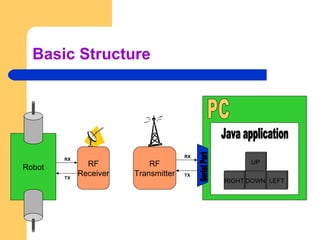
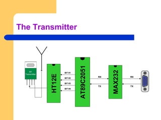
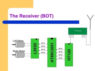
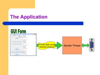
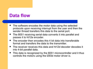
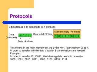
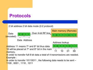
Develop protocol for transferring large data over small bandwidth. This presentation will show you the things involved in making a pc controlled robot.
28. 8251 programmable communication interfacesandip das
The 8251 programmable communication interface chip allows microprocessors like the 8085 to communicate serially. It contains buffers and registers that can convert parallel data from the microprocessor to serial data for transmission to I/O devices and vice versa. The 8251 has a mode word register that specifies characteristics like baud rate and parity, and a command word register that enables transmission and reception. It also has status and data registers for reading communication status and transferring data.
The Read/Write Control logic interfaces the 8251A with CPU, determines the functions of the 8251A according to the control word written into its control register.
It monitors the data flow.
This section has three registers and they are control register, status register and data buffer.
The active low signals RD, WR, CS and C/D(Low) are used for read/write operations with these three registers.
When C/D(low) is high, the control register is selected for writing control word or reading status word.
When C/D(low) is low, the data buffer is selected for read/write operation.
When the reset is high, it forces 8251A into the idle mode.
The clock input is necessary for 8251A for communication with CPU and this clock does not control either the serial transmission or the reception rate.ThesisScientist.com
The document discusses serial communications and common interface standards. It covers:
1) Types of serial communication including asynchronous and synchronous transfer, and simplex, half duplex, and full duplex transfer types.
2) The RS-232 standard for serial communication interfaces between DTE and DCE devices. It specifies voltage levels, connector types, and signal functions.
3) Common interface chips like the 8250/16450/16550 UART used for asynchronous communication and flow control between devices.
The document discusses asynchronous and synchronous serial communication using the 8251A USART chip. It describes the basics of serial communication including synchronous vs asynchronous transmission. It provides details on the components and functioning of the 8251A USART chip, including its transmitter, receiver, control logic and modem control sections. The chip allows for full-duplex serial communication and can operate in both synchronous and asynchronous modes. It converts parallel data from the microprocessor to serial data for transmission and vice versa on reception.
The document describes the architecture of the USART 8251 chip, including its transmitter and receiver sections that convert parallel and serial data, as well as its modem control section. It details the functions of the data bus buffer, transmitter section, receiver section, and modem control signals. The transmitter and receiver sections allow for synchronous and asynchronous communication and contain logic for baud rate generation, parity checking, and error detection.
This document discusses serial communication using the 8085 microprocessor and 8251A USART chip. It describes the basics of synchronous and asynchronous serial transmission including start/stop bits and framing. It provides details on the RS-232 serial interface standard including voltage levels, connectors, and DTE/DCE roles. The 8251A USART chip is explained in detail, including its block diagram, pinout, registers for control, status, and data, and how it converts parallel to serial and vice versa. Modes of operation and initialization of the 8251A are also covered.
1. The document describes a wireless secured remote control system that can be expanded to control more than eight devices. It uses a HCF4555B decoder/multiplexer chip to expand the eight data output lines from the PC to 24 lines, allowing control of up to 24 devices.
2. The system includes a CDMA wireless network, PC, interface circuits, and controlled devices. The PC software can be edited to control any interfaced devices. The HCF4555B chip and interface circuits expand the control capabilities.
3. The performance involves a user entering a password on a mobile phone, which transmits a signal through the CDMA network to a receiving phone connected to the PC. The PC software de
1. To make asynchronous serial communication using a microcontroller's USART, the transmitter must configure the baud rate generator and enable transmission by writing data to the transmit register, while the receiver must configure the baud rate generator and enable reception to read incoming data from the receive register.
2. Key steps include setting the SPBRG register and BRGH bit to determine the baud rate, enabling the serial port and transmission/reception, handling 9-bit data if needed, and checking status registers for transmission completion or errors.
3. Asynchronous serial communication allows microcontrollers to transmit data bit by bit over a single line using start and stop bits for synchronization instead of a separate clock line.
8251 a usart programmable communication interface(1)divyangpit
The document discusses the 8251 programmable communication interface chip. It provides 3 key points:
1. The 8251 is a USART (Universal Synchronous Asynchronous Receiver Transmitter) chip that allows for serial communication and converts parallel data from the CPU to serial data and vice versa.
2. It has sections for data buffering, read/write control, modem control, transmission and reception. It uses control and status registers to program the chip for synchronous or asynchronous modes.
3. The chip can operate in asynchronous or synchronous modes. In asynchronous mode, it adds start and stop bits for transmission and looks for start/stop bits for reception. In synchronous mode, it uses sync characters
The document discusses the USART-8251 chip, which converts parallel data to serial and vice versa. It has sections for a data bus buffer, read/write control logic, modem control, transmitter and receiver. The read/write control logic handles the control and status registers using signals like CS, C/D, WR and RD. The transmitter converts 8-bit parallel data to a serial stream, while the receiver does the opposite. The modem control signals interface with external modems. Overall, the USART-8251 chip facilitates serial communication by converting between serial and parallel formats.
This document discusses serial vs parallel communication and provides details on asynchronous and synchronous serial communication. It also describes the basic components and terms used in serial communication including start bits, stop bits, and baud rate. Finally, it outlines the four operating modes of the 8051 serial port including simple shift register mode, standard UART mode, multiprocessor mode, and a variable baud rate mode.
8251 usart programmable communication interface by aniket bhuteAniket Bhute
This document provides an overview of the 8251A USART chip, including:
- It is a programmable peripheral designed for serial communication that converts parallel data from the CPU to serial and vice versa.
- It has sections for the data bus buffer, read/write control logic, modem control, transmitter and receiver.
- The transmitter accepts parallel data and converts it to serial, while the receiver accepts serial data and converts it to parallel for the CPU.
- It has control, status and data registers that are accessed via various control signals to read/write data and control the chip's operation.
The 8251A is a programmable USART chip that allows for serial communication. It contains a transmitter and receiver section to convert parallel data from the CPU to serial data for transmission and serial to parallel for receiving data. It has control, status and data registers that are accessed by the CPU to program the chip for asynchronous or synchronous communication and monitor transmission status. The chip supports modem control signals and serial communication through pins for transmit, receive and associated control clocks and status lines.
PIC A special purpose integrated circuit that function as an overall manager in an interrupt driven system.
It accepts request from the peripheral equipment,determines which of the incoming request is of the highest priority, ascertains whether the incoming request has a higher priority value than the level currently being serviced, and issues an interrupt to the CPU based on this determination.
The Master Synchronous Serial Port (MSSP) module allows communication with peripheral devices using either Serial Peripheral Interface (SPI) or Inter-Integrated Circuit (I2C) protocols. In SPI mode, data is synchronously transmitted and received on three pins - Serial Data Out, Serial Data In, and Serial Clock. The MSSP has registers for status, control, and buffering data during read and write operations according to the SPI protocol.
The document discusses the Universal Synchronous Asynchronous Receiver Transmitter (USART) which is a serial communication device. It describes the USART's synchronous and asynchronous communication modes and includes a block diagram and explanation of its transmitter, receiver, and pin sections. The USART receives parallel data from a microprocessor and transmits it serially or vice versa while including start/stop bits and potentially parity bits. It was commonly used to connect two microprocessor systems or for modem interfacing.
The document describes the verification of a UART IP core using UVM. It provides details about the key features of UART including the Wishbone interface and baud rate generation. The document outlines the UVM testbench architecture and various test cases verified, including half duplex mode, full duplex mode, loopback mode, and error conditions. Waveforms are shown for different test cases, inputs, and outputs.
Serial data communication involves transmitting digital data between a source and receiver using a communications link. It requires a transmitter to encode the digital data, a communications link to carry the signal, and a receiver to decode the signal. Common components are computers, modems, cables. Transmission can be simplex, half duplex, or full duplex. Formats define start/stop bits, data/parity bits, and transmission speed. Protocols establish rules for data exchange, flow control, error checking, and more. Troubleshooting tools like breakout boxes, null modems, and protocol analyzers help test and diagnose serial communication circuits and connections.
The document describes a UART verification IP core. It consists of a transmitter, receiver, modem interface, baud generator, interrupt controller and control/status registers. The core performs serial-to-parallel and parallel-to-serial conversions. It can operate in 8-bit or 32-bit data bus mode and interfaces with a wishbone bus. The document outlines the UART packet structure, registers, modes of operation, block diagram, UVM verification architecture including transactions, agents, drivers, monitors, sequences, tests and scoreboard. It concludes by summarizing that the UART core was verified for different modes and test cases.
IJRET : International Journal of Research in Engineering and Technology is an international peer reviewed, online journal published by eSAT Publishing House for the enhancement of research in various disciplines of Engineering and Technology. The aim and scope of the journal is to provide an academic medium and an important reference for the advancement and dissemination of research results that support high-level learning, teaching and research in the fields of Engineering and Technology. We bring together Scientists, Academician, Field Engineers, Scholars and Students of related fields of Engineering and Technology.
In telecommunication and computer science, serial communication is the process of sending data one bit at a time, sequentially, over a communication channel or computer bus. This is in contrast to parallel communication, where several bits are sent as a whole, on a link with several parallel channels.
Serial communication is used for all long-haul communication and most computer networks, where the cost of cable and synchronization difficulties make parallel communication impractical. Serial computer buses are becoming more common even at shorter distances, as improved signal integrity and transmission speeds in newer serial technologies have begun to outweigh the parallel bus's advantage of simplicity (no need for serializer and deserializer, or SerDes) and to outstrip its disadvantages (clock skew, interconnect density). The migration from PCI to PCI Express is an example.
Computers can transfer data either in parallel or serially. Parallel transmission sends multiple bits simultaneously over multiple lines, and is used for short distances. Serial transmission sends one bit at a time over a single line, allowing data to be transferred over longer distances but more slowly than parallel. The document discusses using serial communication between a microcontroller and LCD, using ULN 2003 to control devices like stepper motors, DC motors, servos, and relays by sending data bit-by-bit over longer distances.
This document describes a 16550 UART core that provides serial communication functionality. The UART core includes a transmitter, receiver, modem interface, baud generator, interrupt controller, and control/status registers. It supports features like FIFO buffers, various data formats and parity options, interrupt handling, and status reporting. The core is software compatible with existing 16550 UART standards and can communicate with any 16550-compliant device.
UART – Stands for Universal Asynchronous Receiver Transmitter It is a piece of hardware that acts as a bridge between the processor and the serial communication protocol or port (RS-232). It performs parallel – to – serial data conversion at the transmitter side and serial – to – parallel data conversion at the receiver side.Asynchronous serial communication.
A serial communication can be done using fewer wires as compared to its parallel counterpart. It is a cheapest communication device with a single wire for transmitting the data and another wire for receiving. When the high-speed data transfer is not required UART is used. In a simple serial communication, 3 pins are used: TxD, RxD and GND.
At Transmission side (i.e. From Microcontoller), one can write data into UART Data Register (e.g. UART0_DR) by using software code.
These 8 bits of data from Data Register is passed to Tx FIFO Buffer. After that, the data is sent out(one at a time) from Tx Shift Register.
TxFIFO flag = 1 (Buffer full) TxFIFO flag = 0 (not full - Software can write to Data Register)
At Receiver end, there is Rx FIFO Buffer.
RxFIFO Empty flag = 1 (Buffer is empty) RxFIFO Empty flag = 0 (Buffer has data to be read)
A frame is the unit of transmission in serial communications
Start bit: To declare the start of transmission.
Data bits: 4,5,6,7, or 8 bits of useful data bits.
Parity bit : To check for transmission errors.
Stop bit: To declare end of frame
Parity bit is used to check the integrity of a frame and signal if an error occurred during transmission.
It is an extra bit added to the end of a frame.
Even parity :The number of ‘1’ symbols inside a frame must always be even.
Odd parity : The number of ‘1’ symbols inside a frame must always be odd
The configuration settings at both ends of Txd and Rxd:
Full or half-duplex operation
Data length
Start/Stop bits
Transmission speed.
EX:-198 = 11000110
Transmission speed
Common speed = 9600 bits/sec
1/9600 = 104 us.
After detecting start it will count 104us and complets start bit.
Then begins sampling the input bits after 52us with equal count of 104us between each bit untill the next stop bit with high pulse.
Advantages
Requires minimum wires
No need for clock or any other timing signal.
Parity bit ensures basic error checking.
Disadvantages
Size of the data in the frame is limited.
Can connect only two devices at a time
Speed for data transfer is less compared to parallel.
Transmitter and receiver must agree to the rules of transmission and appropriate baud rate must be selected.
if we are looking for a device to device serial communication then UART proves itself the best as it is easy to deal with and also widely used in many peripheral devices.
The document discusses parallel data transfer using the 8155 Programmable Peripheral Interface chip. It describes how the 8155 allows microprocessors like the 8085 to interface with peripheral devices by providing programmable input/output ports and a timer. It has three 8-bit I/O ports (Ports A, B, and C) that can be programmed for simple or handshaked input/output. It also contains 256 bytes of RAM and a 14-bit programmable counter/timer. The 8155 is programmed by writing control words and data to its internal registers to configure the I/O ports and timer operation.
The document discusses serial port programming for the 8051 microcontroller. It describes how serial communication works using one bit at a time instead of parallel communication which transfers all bits at once. It explains the registers and pins used for serial communication on the 8051 including the SBUF, SCON, TMOD registers and MAX232 voltage converter. It provides details on programming the 8051 for serial data transmission and reception by monitoring the TI and RI flags in the SCON register.
The document discusses serial port programming for the 8051 microcontroller. It describes how serial communication works using one bit at a time instead of parallel communication which transfers all bits at once. It explains the registers and pins used for serial communication on the 8051 including the serial data buffer (SBUF) register, serial control (SCON) register, and MAX232 voltage converter. It provides details on programming the 8051 for serial data transmission and reception, including using the TI and RI flags to indicate when data has been sent or received.
Implementation of MIL-STD1553 using Microcontroller Atmega 328PIRJET Journal
This document discusses the implementation of the MIL-STD-1553 protocol using an Arduino ATmega 328P microcontroller. It begins with an abstract that outlines implementing the point-to-point transmission of MIL-STD-1553 data using a hardware platform with an Arduino microcontroller. It then provides background on the MIL-STD-1553 protocol and describes how command words, data words, and status words are formatted. The methodology section explains how data is transferred from a bus controller to a remote terminal using these word formats. It concludes by describing the design and implementation of the protocol using two Arduino microcontrollers, with one as the transmitter and the other as the receiver.
Vehicle tracking system with thiefth protectionSarfz Ahmad
The vehicle tracking system uses an RF electronic license plate to transmit a unique 12-bit code. Roadside receivers detect passing vehicles by receiving their transmitted code and decode the data to access a database with the vehicle's registration details, owner information, and theft status. The system also includes a DTMF-based fuel lock that can be remotely activated or deactivated using a mobile phone to stop a stolen vehicle.
Fire Fighter Robot with Night Vision Camera (1).pptxSyedMohiuddin62
This advanced project Fire Fighter Robotic Vehicle with Night Vision Camera allows a user to control a fire fighter robot equipped with water tank and gun remotely wirelessly for extinguishing fires. For this purposes the system uses an Rf remote for remote operation along with rf receive based microcontroller circuit for operating the robotic vehicle and water pump. The receiver circuit receives RF signals through RF based remote transfer users commands.
This document discusses 8051 serial communication. It describes the key features of 8051 serial communication including full-duplex communication and special function registers. It explains the four different modes of operation and how to double the baud rate. It also provides details on connecting the 8051 to RS232 using a MAX232 chip and provides examples of programs for serial communication.
This document discusses serial communication basics and the 8051 microcontroller's serial port functionality. It describes asynchronous and synchronous serial transmission modes, with asynchronous being character-oriented and using start and stop bits, while synchronous transfers data in blocks. It also outlines the 8051's SBUF, SCON, and PCON registers which control serial communication and data rates. The SCON register controls the serial port mode which can be set to modes 0-3, each with different bit length, clocking, and baud rate determination. The PCON register allows doubling the baud rate by setting the SMOD bit and puts the chip into low power modes.
This document describes a proposed optimal integrated operation strategy for a highway toll collection system using wireless technology. The system would use RFID tags in vehicles and RF receivers at toll gates to electronically collect tolls, eliminating delays. It provides block diagrams of the vehicle and toll gate sections, including the main components like RF modules, microcontrollers, encoders/decoders, and power supplies. The document discusses the advantages of this system in reducing time spent at tolls and references sources for further information.
The document describes technical specifications for multi-function watt-hour meter communication, including physical layer specifications for different interface types (infrared light, serial port), frame formats, and data identifier codes. It defines specifications for signal levels, transfer speeds, frame structure with start/end flags, address fields, error checking, and a four-level tree data structure using a two-byte identifier code to represent different data types and attributes.
This document describes the design of a DS-CDMA transmitter using VHDL and an FPGA. It discusses the design of the transmitter's key components like the PN code generator and BPSK modulator. The PN code generator uses a 16-stage linear feedback shift register with a specific feedback polynomial to generate codes. The transmitter blocks were designed separately in VHDL and then combined and implemented on an FPGA board. The transmitter is capable of transmitting data at rates up to 2 Mbps using a 40 MHz carrier frequency.
This document describes the design and implementation of a serial communication protocol conversion system and circular buffer in an FPGA for monitoring a Tesla meter. The system includes controllers for RS232 and RS485 serial communication, a protocol conversion unit between the two interfaces, and a circular buffer. The controllers are designed using Verilog HDL and implemented on a Spartan FPGA. Simulation and hardware results demonstrate that the system successfully converts between the RS232 and RS485 protocols in real-time and stores data in the circular buffer for offline analysis.
Basic Study on the WT12 Family of Bluetooth DevicesPremier Farnell
This document provides an overview of the WT12 family of Bluetooth devices from Bluegiga Technologies. It describes the key features of WT12 devices including Bluetooth v2.0 + EDR compatibility, integrated chip antenna, industrial temperature range, and support for Enhanced Data Rate and various interfaces. Application areas that can benefit from WT12 devices are also listed. The document includes a block diagram showing the device's architecture and discusses interfaces like UART, SPI and GCI in more detail.
The document discusses interfacing a microcontroller with various peripherals including timers, serial communication, interrupts, LCDs, and keyboards. It provides details on:
- Programming timers in 8051 microcontrollers for time delays and waveform generation.
- Serial communication protocols including asynchronous communication and RS-232 standards.
- Configuring and handling interrupts from different sources and writing interrupt service routines.
- Interfacing 8051 with LCDs for display and matrix keyboards for input using specific I/O ports for scanning rows and columns.
This document discusses implementing host-based HDLC (High-Level Data Link Control) using the quasi-synchronous mode of the Teridian 73M2901CE single chip modem. Quasi-synchronous mode allows a host system with an asynchronous UART interface to communicate synchronous data by removing start and stop bits. The document describes how this works and provides code for HDLC framing and de-framing functions to implement host-based HDLC using quasi-synchronous mode.
This document discusses serial communication with the 8051 microcontroller. It begins by contrasting serial and parallel communication, listing advantages of serial. It then explains asynchronous serial communication protocols. Next, it describes half and full duplex transmission, data framing, transfer rates, and the RS-232 standard. Finally, it provides examples of initializing and programming the 8051 for serial communication using timers, registers, and algorithms.
The document discusses the 8251A USART chip, which can be used for both asynchronous and synchronous serial communication. It describes the basic components and functions of the 8251A chip, including its transmitter and receiver sections that convert parallel to serial data and vice versa. The document also explains the differences between asynchronous and synchronous serial communication and covers various control signals and registers used by the 8251A for data transfer and interfacing with external devices like modems.
"Emblogic.com" is the best education center in India to assist you about serial port device driver and their development as well. To know more about these kind of training program, visit our professional website.
This presentation discusses the Serial Communication features in 8051, the support for UART. It also discusses serial vs parallel communication, simplex, duplex and full-duplex modes, MAX232, RS232 standards
The document discusses asynchronous and synchronous data transfer using the 8251A USART chip. It describes the basics of serial communication including synchronous vs asynchronous transmission. It provides details on the sections and functioning of the 8251A chip, including its transmitter, receiver, and modem control sections. The pin diagram and functions of the pins are also explained.
This document describes an RF ID based access control system. The system uses an RF transmitter kit that sends an RF ID to a receiver circuit. If the received ID matches the data in the receiver, the name of the RF ID holder is displayed on an LCD. The project is divided into three parts: 1) RF ID code transmission using an RF ID encoder IC, 2) Receiving the RF ID data using the main receiver, 3) Opening the door if the password matches. A master can also open the door with a password.
DEEP LEARNING FOR SMART GRID INTRUSION DETECTION: A HYBRID CNN-LSTM-BASED MODELgerogepatton
As digital technology becomes more deeply embedded in power systems, protecting the communication
networks of Smart Grids (SG) has emerged as a critical concern. Distributed Network Protocol 3 (DNP3)
represents a multi-tiered application layer protocol extensively utilized in Supervisory Control and Data
Acquisition (SCADA)-based smart grids to facilitate real-time data gathering and control functionalities.
Robust Intrusion Detection Systems (IDS) are necessary for early threat detection and mitigation because
of the interconnection of these networks, which makes them vulnerable to a variety of cyberattacks. To
solve this issue, this paper develops a hybrid Deep Learning (DL) model specifically designed for intrusion
detection in smart grids. The proposed approach is a combination of the Convolutional Neural Network
(CNN) and the Long-Short-Term Memory algorithms (LSTM). We employed a recent intrusion detection
dataset (DNP3), which focuses on unauthorized commands and Denial of Service (DoS) cyberattacks, to
train and test our model. The results of our experiments show that our CNN-LSTM method is much better
at finding smart grid intrusions than other deep learning algorithms used for classification. In addition,
our proposed approach improves accuracy, precision, recall, and F1 score, achieving a high detection
accuracy rate of 99.50%.
Advanced control scheme of doubly fed induction generator for wind turbine us...IJECEIAES
This paper describes a speed control device for generating electrical energy on an electricity network based on the doubly fed induction generator (DFIG) used for wind power conversion systems. At first, a double-fed induction generator model was constructed. A control law is formulated to govern the flow of energy between the stator of a DFIG and the energy network using three types of controllers: proportional integral (PI), sliding mode controller (SMC) and second order sliding mode controller (SOSMC). Their different results in terms of power reference tracking, reaction to unexpected speed fluctuations, sensitivity to perturbations, and resilience against machine parameter alterations are compared. MATLAB/Simulink was used to conduct the simulations for the preceding study. Multiple simulations have shown very satisfying results, and the investigations demonstrate the efficacy and power-enhancing capabilities of the suggested control system.
Optimizing Gradle Builds - Gradle DPE Tour Berlin 2024Sinan KOZAK
Sinan from the Delivery Hero mobile infrastructure engineering team shares a deep dive into performance acceleration with Gradle build cache optimizations. Sinan shares their journey into solving complex build-cache problems that affect Gradle builds. By understanding the challenges and solutions found in our journey, we aim to demonstrate the possibilities for faster builds. The case study reveals how overlapping outputs and cache misconfigurations led to significant increases in build times, especially as the project scaled up with numerous modules using Paparazzi tests. The journey from diagnosing to defeating cache issues offers invaluable lessons on maintaining cache integrity without sacrificing functionality.
Using recycled concrete aggregates (RCA) for pavements is crucial to achieving sustainability. Implementing RCA for new pavement can minimize carbon footprint, conserve natural resources, reduce harmful emissions, and lower life cycle costs. Compared to natural aggregate (NA), RCA pavement has fewer comprehensive studies and sustainability assessments.
Presentation of IEEE Slovenia CIS (Computational Intelligence Society) Chapte...University of Maribor
Slides from talk presenting:
Aleš Zamuda: Presentation of IEEE Slovenia CIS (Computational Intelligence Society) Chapter and Networking.
Presentation at IcETRAN 2024 session:
"Inter-Society Networking Panel GRSS/MTT-S/CIS
Panel Session: Promoting Connection and Cooperation"
IEEE Slovenia GRSS
IEEE Serbia and Montenegro MTT-S
IEEE Slovenia CIS
11TH INTERNATIONAL CONFERENCE ON ELECTRICAL, ELECTRONIC AND COMPUTING ENGINEERING
3-6 June 2024, Niš, Serbia
International Conference on NLP, Artificial Intelligence, Machine Learning an...gerogepatton
International Conference on NLP, Artificial Intelligence, Machine Learning and Applications (NLAIM 2024) offers a premier global platform for exchanging insights and findings in the theory, methodology, and applications of NLP, Artificial Intelligence, Machine Learning, and their applications. The conference seeks substantial contributions across all key domains of NLP, Artificial Intelligence, Machine Learning, and their practical applications, aiming to foster both theoretical advancements and real-world implementations. With a focus on facilitating collaboration between researchers and practitioners from academia and industry, the conference serves as a nexus for sharing the latest developments in the field.
A SYSTEMATIC RISK ASSESSMENT APPROACH FOR SECURING THE SMART IRRIGATION SYSTEMSIJNSA Journal
The smart irrigation system represents an innovative approach to optimize water usage in agricultural and landscaping practices. The integration of cutting-edge technologies, including sensors, actuators, and data analysis, empowers this system to provide accurate monitoring and control of irrigation processes by leveraging real-time environmental conditions. The main objective of a smart irrigation system is to optimize water efficiency, minimize expenses, and foster the adoption of sustainable water management methods. This paper conducts a systematic risk assessment by exploring the key components/assets and their functionalities in the smart irrigation system. The crucial role of sensors in gathering data on soil moisture, weather patterns, and plant well-being is emphasized in this system. These sensors enable intelligent decision-making in irrigation scheduling and water distribution, leading to enhanced water efficiency and sustainable water management practices. Actuators enable automated control of irrigation devices, ensuring precise and targeted water delivery to plants. Additionally, the paper addresses the potential threat and vulnerabilities associated with smart irrigation systems. It discusses limitations of the system, such as power constraints and computational capabilities, and calculates the potential security risks. The paper suggests possible risk treatment methods for effective secure system operation. In conclusion, the paper emphasizes the significant benefits of implementing smart irrigation systems, including improved water conservation, increased crop yield, and reduced environmental impact. Additionally, based on the security analysis conducted, the paper recommends the implementation of countermeasures and security approaches to address vulnerabilities and ensure the integrity and reliability of the system. By incorporating these measures, smart irrigation technology can revolutionize water management practices in agriculture, promoting sustainability, resource efficiency, and safeguarding against potential security threats.
Understanding Inductive Bias in Machine LearningSUTEJAS
This presentation explores the concept of inductive bias in machine learning. It explains how algorithms come with built-in assumptions and preferences that guide the learning process. You'll learn about the different types of inductive bias and how they can impact the performance and generalizability of machine learning models.
The presentation also covers the positive and negative aspects of inductive bias, along with strategies for mitigating potential drawbacks. We'll explore examples of how bias manifests in algorithms like neural networks and decision trees.
By understanding inductive bias, you can gain valuable insights into how machine learning models work and make informed decisions when building and deploying them.
6. Data flow
The software encodes the motor data using the selected
protocols upon receiving interrupt from the user and then the
sender thread transfers this data to the serial port.
The 8051 receiving serial data converts it into parallel and
passes it to ht12e encoder.
The encoder then encodes this 4 bit data into transferable
format and transfers the data to the transmitter.
The receiver receives this data and ht12d decoder decodes it
into 4-bit parallel data.
This data is recognized by the 8051 microcontroller and it thus
controls the motors using the l293d motor driver ic.
7. Protocols
3 bit address 1 bit data mode (3-1 protocol)
1 0 1 1
Address
Main memory (Remote)
1 0 1 1 1 0 1 1
Main memory (Remote)
Data
(encoded)
Data
This means in the main memory set the 3rd
bit (011) (starting from 0) as 1.
In order to transfer full 8 bit data a total of 8 transmissions are needed.
Example :
In order to transfer 10110011 , the following data needs to be sent –
1000 , 1001 , 0010 , 0011 , 1100 , 1101 , 0110 , 1111
Over 4-bit RF line
8. Protocols
2 bit address 2 bit data mode (2-2 protocol)
1 0 1 1
Address
Main memory (Remote)
1 0 1 1 1 0 1 1
Data
(encoded)
Data
Address 11 means 7th
and 8th
bit thus data
10 will be placed at 7th
and 8th
bit in the main
memory.
In order to transfer full 8 bit data a total of 4 transmissions are needed.
Example :
In order to transfer 10110011 , the following data needs to be sent –
1100 , 0001 , 1110 , 1011
Over 4-bit RF line
1 0 1 1 1 0 1 1
Address lookup
0000011011
9. Advantages of these protocols
3-1 protocol is slower than 2-2 protocol but is more efficient in
transferring single bits.
These protocols ensure there is no loss of data , while
transferring large data over small data packet size.
2-2 protocol is more efficient in this case as it modifies 2 bits all
together . One motors need 2-bit data. Thus for controlling 2
motors a total of 4 bits in the main memory will be needed
hence the data will be transferred in only 2 transmissions (with
2-2 protocol) or in 4 transmissions (with 3-1 protocol).
The remaining 4 bits can be used for some other data like
headlights and horn (Note : I am limited to one direction data
transfer).
10. Software architecture
Sender ThreadEncode data using
selected protocol
Sender ThreadEncode data using
selected protocol
The user can either control the robot using
Arrow keys or buttons. It also has bit edit
Functionality to send custom data to the
Robot. As soon as the user presses a arrow key an the sender thread calls the
Required command sequence and sends to the serial port. (Note : only starting
4 – bits are used)
Turn left :
send 00000000
delay
send 00001010
delay
Turn Right :
send 00000000
delay
send 00000101
delay
Forward :
send 00000000
delay
send 00000110
delay
Backward :
send 00000000
delay
send 00001001
delay
11. Precautions of motor control
The dc motors connected to the motor driver
cannot be turned instantaneously rather a
delay (minimum of 50 ms) is required while
turning from one direction to another.