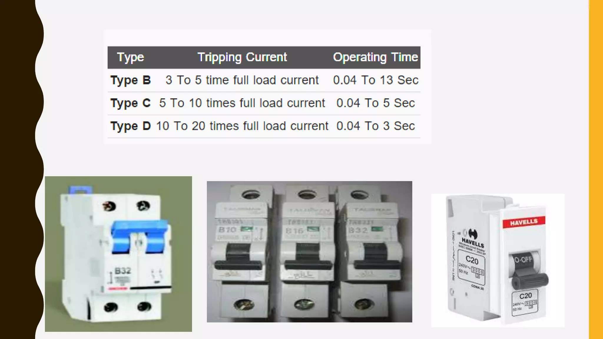
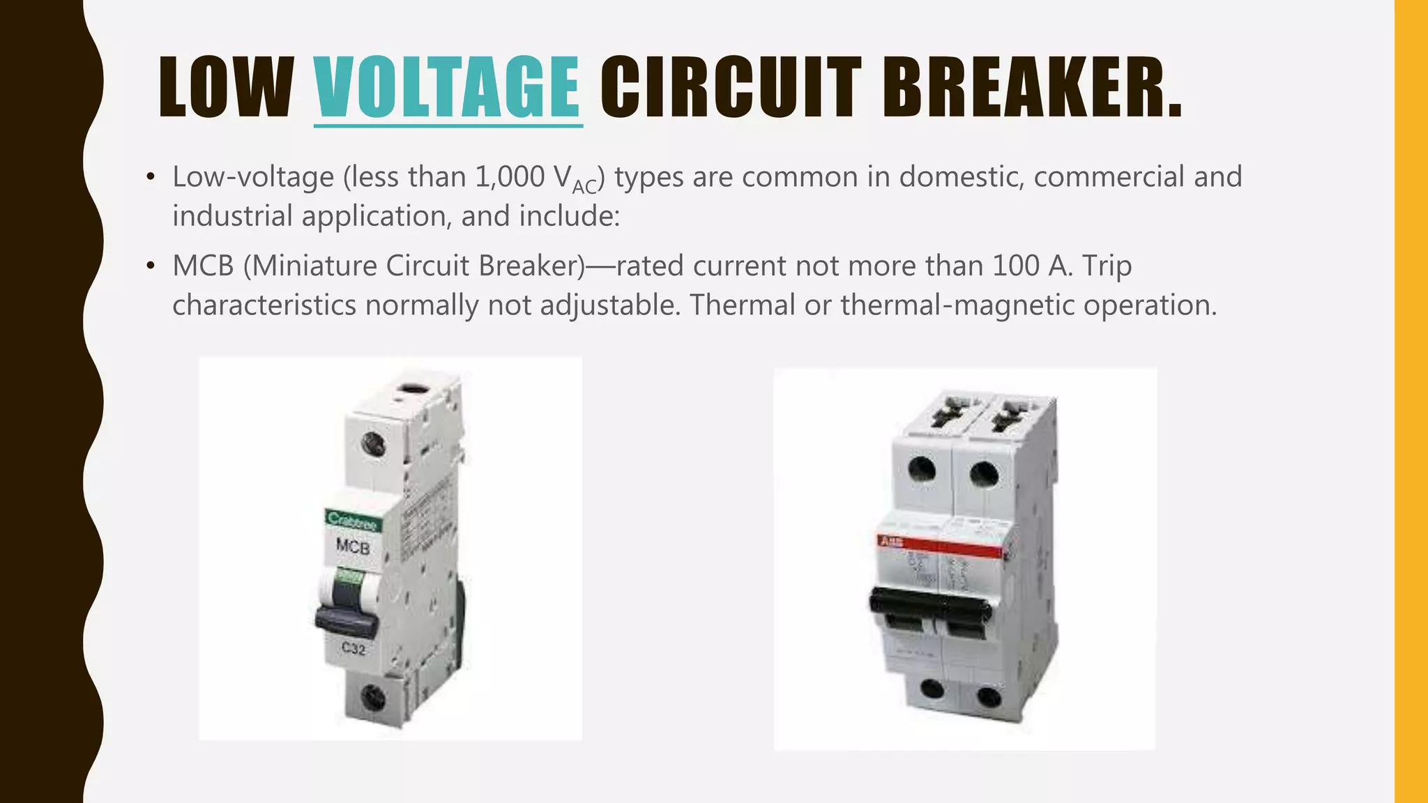
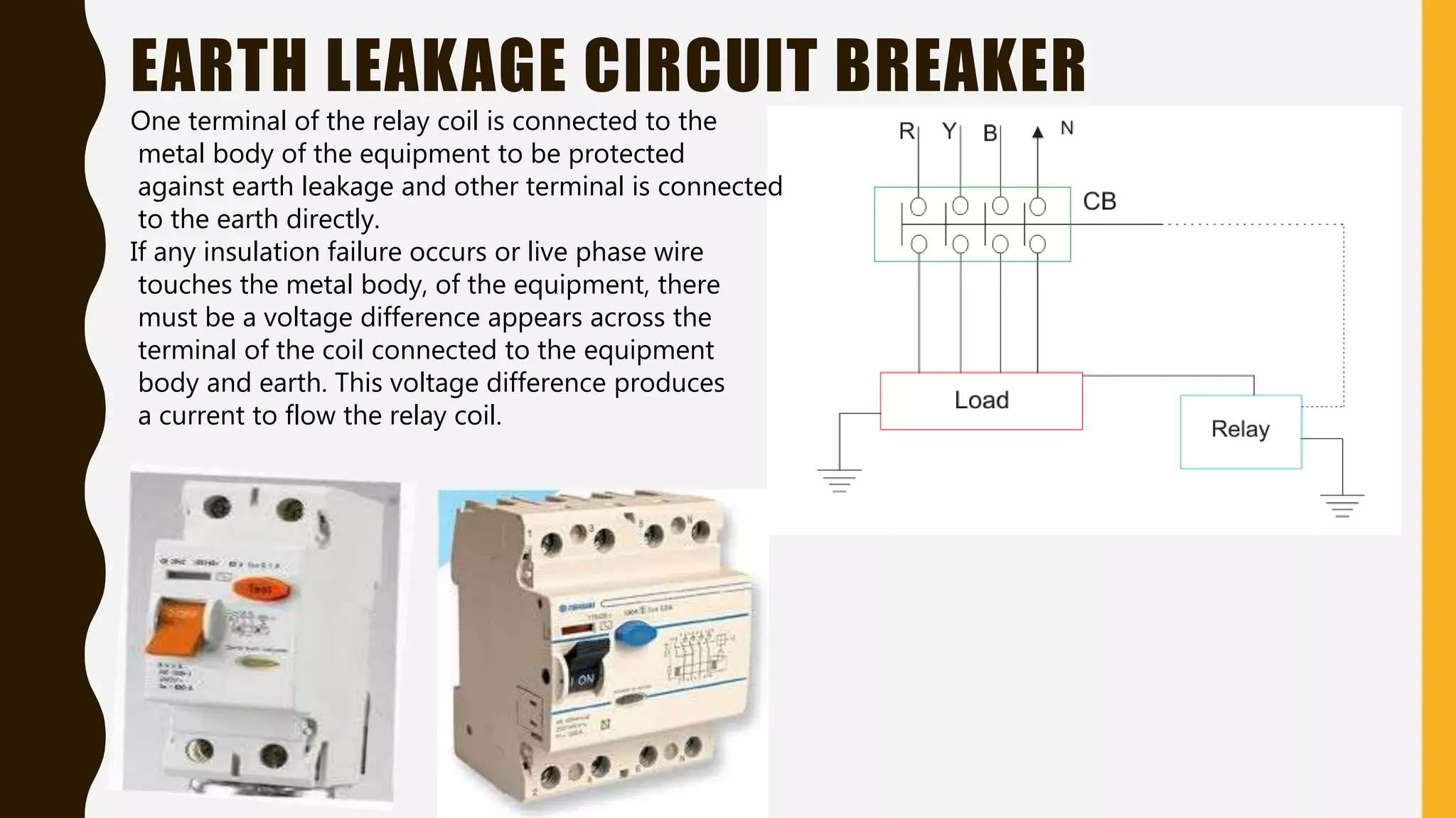
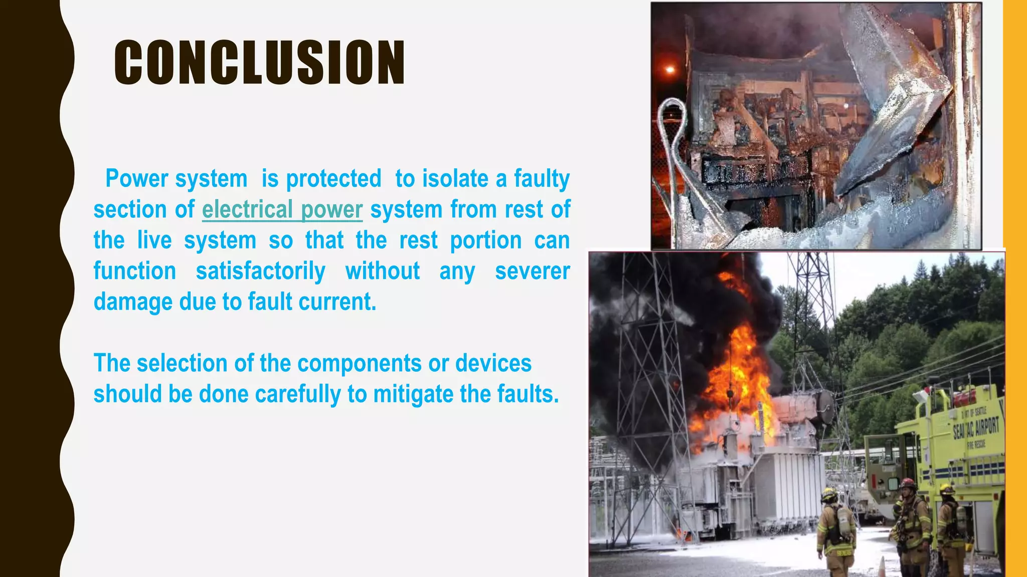
POWER SYSTEM
PROTECTION DEVICES
P R A K A S H K U M A R
THIS SEMINAR WILL COVER:
OBJECTIVE OF PROTECTION
COMPONENTS OF POWER SYSTEM NEED TO BE PROTECTED
PROTECTION DEVICES
RALAYS AND ITS TYPE
CIRCUIT BREAEKRS AND ITS TYPE
OTHER BREAKERS
OBJECTIVE OF POWER SYSTEM PROTECTION
• To isolate a faulty section of electrical power system
from rest of the live system so that the rest portion
can function satisfactorily without any severer damage
due to fault current.
Selection of protective relays requires compromises:
• Maximum and Reliable protection at minimum equipment
cost
• High Sensitivity to faults and insensitivity to maximum load
currents
• High-speed fault clearance with correct selectivity
• Ability to operate correctly under all predictable power
system conditions.
ART & SCIENCE OF PROTECTION
COMPONENTS OF POWER SYSTEM
NEEDS TO BE PROTECTED.
• GENERATORS
• TRANSFORMERS
• BUS-BARS
• TRANSMISSION LINES
PROTECTIVE SYSTEM ELEMENTS
• FUSES
• PROTECTIVE RELAYS
• CIRCUIT BREAKERS
• INSTRUMENT TRANSFORMERS (C.T. & P.T.)
• DC SUPPLY SYSTEM
FUSES
• A fuse is a type of low resistance resistor that acts as a sacrificial device to
provide overcurrent protection.
• A fuse interrupts an excessive current so that further damage by overheating or fire is
prevented.
RELAYS
A protective relay is a compact device designed to sense the abnormal condition and trip
a circuit breaker when a fault is detected
TYPES OF RELAYS:
• ELECTROMECHANICAL RELAYS
• STATIC RELAYS
• NUMERICAL RELAYS
• THERMAL RELAYS
ELECTROMECHANICAL RELAYS
STATIC RELAYS
• Static relays have no moving parts . Measuring elements of static relays have been
successfully and economically built up from diodes, zener diodes, p-n-p and n-p-n
transistors, field effect transistors or their combinations
• Higher sensitive than purely electromechanical relays.
• provide fast operation, long life and low maintenance.
THERMAL RELAYS
The basic working principle of thermal relay is that, when a bimetallic strip is heated up
by a heating coil carrying over current of the system, it bends and makes normally open
contacts.
NUMERICAL RELAYS
The relay has multiple microprocessor design. The microprocessors perform the software
function such as signal processing , protection algorithm , and handling the human
interface.
CIRCUIT BREAKER
• A circuit breaker is an automatically operated electrical switch designed to protect an
electrical circuit from damage caused by Overcurrent/overload or short circuit. Its basic
function is to interrupt current flow after Protective relays detect faults condition.
• The commonly-available preferred values for the
rated current are 6 A, 10 A, 13 A, 16 A, 20 A, 25 A,
32 A, 40 A, 50 A, 63 A, 80 A, 100 A and 125 A.
• The circuit breaker is labeled with the
rated current in amperes, but without
the unit symbol "A". Instead, the ampere
figure is preceded by a letter "B", "C" or "D",
which indicates the instantaneous tripping current
TYPES OF CIRCUIT BREAKER
According to their arc quenching media
the circuit breaker can be divided as-
• Oil circuit breaker.
• Air circuit breaker.
• SF6 circuit breaker.
• Vacuum circuit breaker.
According to the voltage level of installation types of
circuit breaker are referred as-
• High voltage circuit breaker.
• Medium voltage circuit breaker.
• Low voltage circuit breaker.
LOW VOLTAGE CIRCUIT BREAKER.
• Low-voltage (less than 1,000 VAC) types are common in domestic, commercial and
industrial application, and include:
• MCB (Miniature Circuit Breaker)—rated current not more than 100 A. Trip
characteristics normally not adjustable. Thermal or thermal-magnetic operation.
MEDIUM VOLTAGE CIRCUIT BREAKER
• Medium-voltage circuit breakers rated between 1 and 72 kV may be assembled into
metal-enclosed switchgear line ups for indoor use, or may be individual components
installed outdoors in a substation.
HIGH VOLTAGE CIRCUIT BREAKER
• Electrical power transmission networks are protected and controlled by high-voltage
breakers. The definition of high voltage varies but in power transmission work is
usually thought to be 72.5 kV or higher.
OTHER BREAKERS
• Recloser—A type of circuit breaker that closes
automatically after a delay. These are used on
overhead electric power distribution
systems, to prevent short duration faults
from causing sustained outages.
• Polyswitch —Also known as resettable fuse , made of crystalline
polymers. Used in computer power supply , aerospace and
nuclear application and loudspeakers.
EARTH LEAKAGE CIRCUIT BREAKER
One terminal of the relay coil is connected to the
metal body of the equipment to be protected
against earth leakage and other terminal is connected
to the earth directly.
If any insulation failure occurs or live phase wire
touches the metal body, of the equipment, there
must be a voltage difference appears across the
terminal of the coil connected to the equipment
body and earth. This voltage difference produces
a current to flow the relay coil.
Residual Current Circuit Breaker
One CT core is energized from both phase wire and neutral
wire. The polarity of the phase winding and neutral winding
on the core is so chosen that, in normal condition mmf of
one winding opposes that of another.
In normal operating conditions the current goes through the
phase wire will be returned via neutral wire if there's no
leakage in between.
• Current transformers are used to step primary system currents to
values usable by relays, meters, SCADA, transducers, etc.
• CT ratios are expressed as primary to secondary; 2000:5, 1200:5,
600:5, 300:5
• A 2000:5 CT has a “CTR” of 400
Current Transformers
VP
VS
Relay
• Voltage (potential) transformers are used to isolate and step down
and accurately reproduce the scaled voltage for the protective
device or relay
• VT ratios are typically expressed as primary to secondary;
14400:120, 7200:120
• A 4160:120 VT has a “VTR” of 34.66
Voltage Transformers
DC SUPPLY SYSTEM
All the circuit breakers of electrical power system
are DC (Direct Current) operated. Because DC
power can be stored in battery and if situation
comes when total failure of incoming power
occurs, still the circuit breakers can be operated
for restoring the situation by the power of storage
battery.
CONCLUSION
Power system is protected to isolate a faulty
section of electrical power system from rest of
the live system so that the rest portion can
function satisfactorily without any severer
damage due to fault current.
The selection of the components or devices
should be done carefully to mitigate the faults.
REFERENCES
http://www.electrical4u.com/protection-system-in-power-system/
https://en.wikipedia.org/wiki/Power-system_protection
www.electrical-engineering-portal.com
Protection-and-Switchgear-by-U.A.Bakshi-and-M.V.Bakshi

powersystemprotectiondevices-161120193617 (1).pdf

  • 1.
    POWER SYSTEM PROTECTION DEVICES PR A K A S H K U M A R
  • 2.
    THIS SEMINAR WILLCOVER: OBJECTIVE OF PROTECTION COMPONENTS OF POWER SYSTEM NEED TO BE PROTECTED PROTECTION DEVICES RALAYS AND ITS TYPE CIRCUIT BREAEKRS AND ITS TYPE OTHER BREAKERS
  • 3.
    OBJECTIVE OF POWERSYSTEM PROTECTION • To isolate a faulty section of electrical power system from rest of the live system so that the rest portion can function satisfactorily without any severer damage due to fault current.
  • 4.
    Selection of protectiverelays requires compromises: • Maximum and Reliable protection at minimum equipment cost • High Sensitivity to faults and insensitivity to maximum load currents • High-speed fault clearance with correct selectivity • Ability to operate correctly under all predictable power system conditions. ART & SCIENCE OF PROTECTION
  • 5.
    COMPONENTS OF POWERSYSTEM NEEDS TO BE PROTECTED. • GENERATORS • TRANSFORMERS • BUS-BARS • TRANSMISSION LINES
  • 6.
    PROTECTIVE SYSTEM ELEMENTS •FUSES • PROTECTIVE RELAYS • CIRCUIT BREAKERS • INSTRUMENT TRANSFORMERS (C.T. & P.T.) • DC SUPPLY SYSTEM
  • 7.
    FUSES • A fuseis a type of low resistance resistor that acts as a sacrificial device to provide overcurrent protection. • A fuse interrupts an excessive current so that further damage by overheating or fire is prevented.
  • 8.
    RELAYS A protective relayis a compact device designed to sense the abnormal condition and trip a circuit breaker when a fault is detected
  • 9.
    TYPES OF RELAYS: •ELECTROMECHANICAL RELAYS • STATIC RELAYS • NUMERICAL RELAYS • THERMAL RELAYS
  • 10.
  • 11.
    STATIC RELAYS • Staticrelays have no moving parts . Measuring elements of static relays have been successfully and economically built up from diodes, zener diodes, p-n-p and n-p-n transistors, field effect transistors or their combinations • Higher sensitive than purely electromechanical relays. • provide fast operation, long life and low maintenance.
  • 12.
    THERMAL RELAYS The basicworking principle of thermal relay is that, when a bimetallic strip is heated up by a heating coil carrying over current of the system, it bends and makes normally open contacts.
  • 13.
    NUMERICAL RELAYS The relayhas multiple microprocessor design. The microprocessors perform the software function such as signal processing , protection algorithm , and handling the human interface.
  • 14.
    CIRCUIT BREAKER • Acircuit breaker is an automatically operated electrical switch designed to protect an electrical circuit from damage caused by Overcurrent/overload or short circuit. Its basic function is to interrupt current flow after Protective relays detect faults condition. • The commonly-available preferred values for the rated current are 6 A, 10 A, 13 A, 16 A, 20 A, 25 A, 32 A, 40 A, 50 A, 63 A, 80 A, 100 A and 125 A. • The circuit breaker is labeled with the rated current in amperes, but without the unit symbol "A". Instead, the ampere figure is preceded by a letter "B", "C" or "D", which indicates the instantaneous tripping current
  • 16.
    TYPES OF CIRCUITBREAKER According to their arc quenching media the circuit breaker can be divided as- • Oil circuit breaker. • Air circuit breaker. • SF6 circuit breaker. • Vacuum circuit breaker. According to the voltage level of installation types of circuit breaker are referred as- • High voltage circuit breaker. • Medium voltage circuit breaker. • Low voltage circuit breaker.
  • 17.
    LOW VOLTAGE CIRCUITBREAKER. • Low-voltage (less than 1,000 VAC) types are common in domestic, commercial and industrial application, and include: • MCB (Miniature Circuit Breaker)—rated current not more than 100 A. Trip characteristics normally not adjustable. Thermal or thermal-magnetic operation.
  • 18.
    MEDIUM VOLTAGE CIRCUITBREAKER • Medium-voltage circuit breakers rated between 1 and 72 kV may be assembled into metal-enclosed switchgear line ups for indoor use, or may be individual components installed outdoors in a substation.
  • 19.
    HIGH VOLTAGE CIRCUITBREAKER • Electrical power transmission networks are protected and controlled by high-voltage breakers. The definition of high voltage varies but in power transmission work is usually thought to be 72.5 kV or higher.
  • 20.
    OTHER BREAKERS • Recloser—Atype of circuit breaker that closes automatically after a delay. These are used on overhead electric power distribution systems, to prevent short duration faults from causing sustained outages. • Polyswitch —Also known as resettable fuse , made of crystalline polymers. Used in computer power supply , aerospace and nuclear application and loudspeakers.
  • 21.
    EARTH LEAKAGE CIRCUITBREAKER One terminal of the relay coil is connected to the metal body of the equipment to be protected against earth leakage and other terminal is connected to the earth directly. If any insulation failure occurs or live phase wire touches the metal body, of the equipment, there must be a voltage difference appears across the terminal of the coil connected to the equipment body and earth. This voltage difference produces a current to flow the relay coil.
  • 22.
    Residual Current CircuitBreaker One CT core is energized from both phase wire and neutral wire. The polarity of the phase winding and neutral winding on the core is so chosen that, in normal condition mmf of one winding opposes that of another. In normal operating conditions the current goes through the phase wire will be returned via neutral wire if there's no leakage in between.
  • 23.
    • Current transformersare used to step primary system currents to values usable by relays, meters, SCADA, transducers, etc. • CT ratios are expressed as primary to secondary; 2000:5, 1200:5, 600:5, 300:5 • A 2000:5 CT has a “CTR” of 400 Current Transformers
  • 24.
    VP VS Relay • Voltage (potential)transformers are used to isolate and step down and accurately reproduce the scaled voltage for the protective device or relay • VT ratios are typically expressed as primary to secondary; 14400:120, 7200:120 • A 4160:120 VT has a “VTR” of 34.66 Voltage Transformers
  • 25.
    DC SUPPLY SYSTEM Allthe circuit breakers of electrical power system are DC (Direct Current) operated. Because DC power can be stored in battery and if situation comes when total failure of incoming power occurs, still the circuit breakers can be operated for restoring the situation by the power of storage battery.
  • 26.
    CONCLUSION Power system isprotected to isolate a faulty section of electrical power system from rest of the live system so that the rest portion can function satisfactorily without any severer damage due to fault current. The selection of the components or devices should be done carefully to mitigate the faults.
  • 27.