Downloaded 514 times

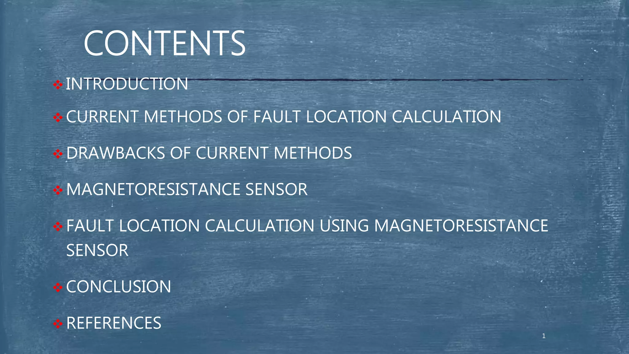


The seminar discusses fault location methods for overhead transmission lines, emphasizing current techniques like impedance-measurement and travelling-wave approaches, and their limitations. A novel method utilizing magnetoresistance sensors for fault detection is proposed, benefiting from advancements in sensor technology and data processing. This efficient and cost-effective solution aims to improve fault identification and location accuracy in power systems.