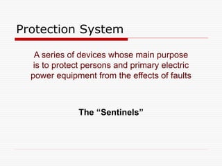
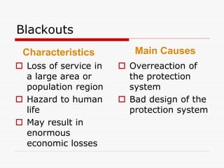
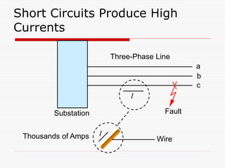
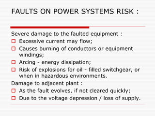
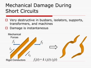
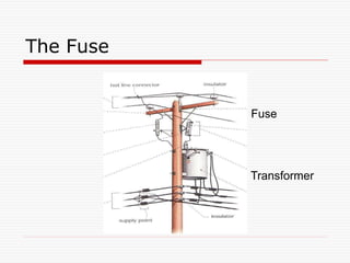
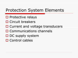
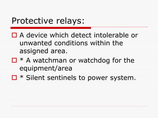
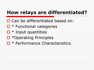
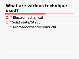
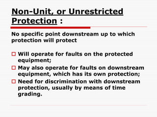
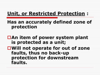
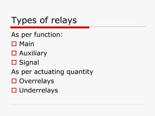
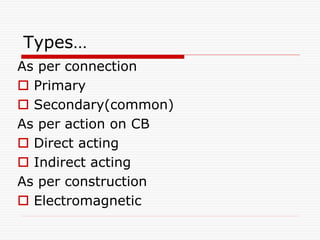
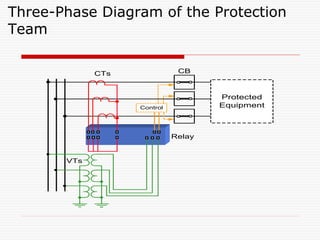
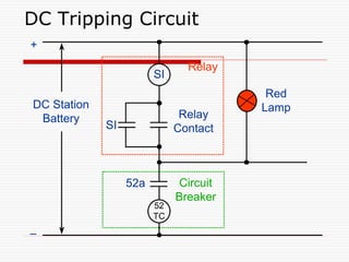
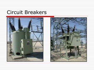
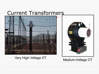
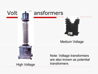
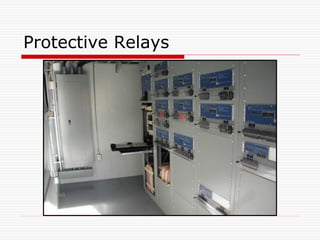
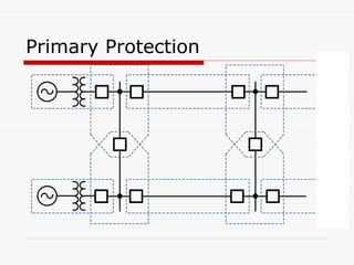
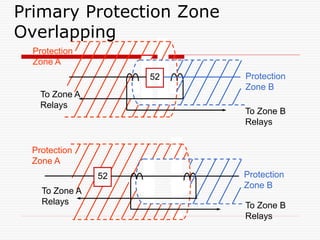
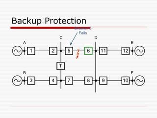
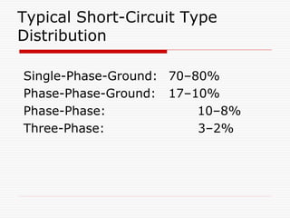
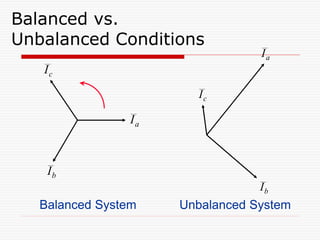
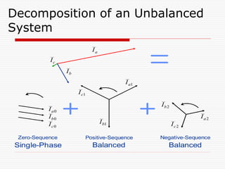
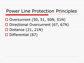
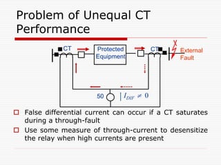
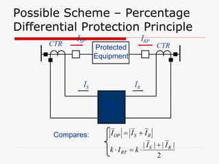
Agenda
 Why protection is needed
 Principles and elements of the
protection system
 Basic protection schemes
 Digital relay advantages and
enhancements
Disturbances: Light or Severe
 The power system must maintain acceptable
operation 24 hours a day
 Voltage and frequency must stay within certain
limits
 Small disturbances
 The control system can handle these
 Example: variation in transformer or generator
load
 Severe disturbances require a protection system
 They can jeopardize the entire power system
 They cannot be overcome by a control system
Power System Protection
Operation during severe disturbances:
 System element protection
 System protection
 Automatic reclosing
 Automatic transfer to alternate power
supplies
 Automatic synchronization
Electric Power System Exposure to
External Agents
Damage to Main Equipment
Protection System
A series of devices whose main purpose
is to protect persons and primary electric
power equipment from the effects of faults
The “Sentinels”
Blackouts
 Loss of service in
a large area or
population region
 Hazard to human
life
 May result in
enormous
economic losses
 Overreaction of
the protection
system
 Bad design of the
protection system
Characteristics Main Causes
Short Circuits Produce High
Currents
Fault
Substation
a
b
c
I
I
Wire
Three-Phase Line
Thousands of Amps
FAULTS ON POWER SYSTEMS RISK :
Severe damage to the faulted equipment :
 Excessive current may flow;
 Causes burning of conductors or equipment
windings;
 Arcing - energy dissipation;
 Risk of explosions for oil - filled switchgear, or
when in hazardous environments.
Damage to adjacent plant :
 As the fault evolves, if not cleared quickly;
 Due to the voltage depression / loss of supply.
Mechanical Damage During
Short Circuits
 Very destructive in busbars, isolators, supports,
transformers, and machines
 Damage is instantaneous
i1
i2
f1 f2
Rigid Conductors f1(t) = k i1(t) i2(t)
Mechanical
Forces
The Fuse
Fuse
Transformer
Essential qualities of
protection:
 Reliability
 Selectivity-
Absolute or relative
 Fastness
 Discrimination
Protection System Elements
 Protective relays
 Circuit breakers
 Current and voltage transducers
 Communications channels
 DC supply system
 Control cables
Protective relays:
 A device which detect intolerable or
unwanted conditions within the
assigned area.
 * A watchman or watchdog for the
equipment/area
 * Silent sentinels to power system.
How relays are differentiated?
 Can be differentiated based on:
 * Functional categories
 * Input quantities
 *Operating Principles
 * Performance Characteristics.
What are various design
criteria?
 * Dependability/Reliability
 * Security
 * Selectivity
 *Speed
 * Simplicity/flexibility
 *Stability
 *Performance Vs. Economy
What are various technique
used?
 * Electromechanical
 *Solid state/Static
 * Microprocessor/Numerical
Non-Unit, or Unrestricted
Protection :
No specific point downstream up to which
protection will protect
 Will operate for faults on the protected
equipment;
 May also operate for faults on downstream
equipment, which has its own protection;
 Need for discrimination with downstream
protection, usually by means of time
grading.
Unit, or Restricted Protection :
Has an accurately defined zone of
protection
An item of power system plant
is protected as a unit;
Will not operate for out of zone
faults, thus no back-up
protection for downstream
faults.
Types of relays
As per function:
 Main
 Auxiliary
 Signal
As per actuating quantity
 Overrelays
 Underrelays
Types…
As per connection
 Primary
 Secondary(common)
As per action on CB
 Direct acting
 Indirect acting
As per construction
 Electromagnetic
Types..
 Static
 Numerical
As per comparator types
 Single input comparator
 Two input comparator
 Multiple input comparator
Methods of disciminations:
 To locate fault
by time
by current grading
by time and direction
by distance
by time, current and distance
by current balance
by power direction comparison
 Type of fault
Three-Phase Diagram of the Protection
Team
CTs
VTs
Relay
CB
Control
Protected
Equipment
DC Tripping Circuit
SI
52
TC
DC Station
Battery
SI
Relay
Contact
Relay
Circuit
Breaker
52a
+
–
Red
Lamp
Circuit Breakers
Current Transformers
Very High Voltage CT
Medium-Voltage CT
Voltage Transformers
Medium Voltage
High Voltage
Note: Voltage transformers
are also known as potential
transformers
Protective Relays
Examples of Relay Panels
Old Electromechanical
Microprocessor-
Based Relay
How Do Relays Detect Faults?
 When a fault takes place, the current, voltage,
frequency, and other electrical variables behave in a
peculiar way. For example:
 Current suddenly increases
 Voltage suddenly decreases
 Relays can measure the currents and the voltages
and detect that there is an overcurrent, or an under
voltage, or a combination of both
 Many other detection principles determine the design
of protective relays
Primary Protection
Primary Protection Zone
Overlapping
Protection
Zone B
Protection
Zone A
To Zone B
Relays
To Zone A
Relays
52 Protection
Zone B
Protection
Zone A
To Zone B
Relays
To Zone A
Relays
52
Backup Protection
A
C D
E
Breaker 5
Fails
1 2 5 6 11 12
T
3 4 7 8 9 10
B F
Typical Short-Circuit Type
Distribution
Single-Phase-Ground: 70–80%
Phase-Phase-Ground: 17–10%
Phase-Phase: 10–8%
Three-Phase: 3–2%
Balanced vs.
Unbalanced Conditions
Balanced System Unbalanced System
c
I
a
I
b
I
a
I
c
I
b
I
Decomposition of an Unbalanced
System
Positive-Sequence
Balanced Balanced
Negative-Sequence
1
b
I
1
c
I
1
a
I
2
b
I
2
a
I
2
c
I
0
a
I
0
b
I
0
c
I
a
I
c
I
b
I
Zero-Sequence
Single-Phase
Power Line Protection Principles
 Overcurrent (50, 51, 50N, 51N)
 Directional Overcurrent (67, 67N)
 Distance (21, 21N)
 Differential (87)
Characteristics of overcurrent
relays:
 Definite time
 IDMT- inverse definite minimum time
 Very inverse
 Extremely inverse
Application of Inverse-Type
Relays
t
Relay
Operation
Time
I
Fault Load
Radial Line
Distance
Distance
t
I
  
T

Inverse-Time Relay
Coordination
T
 T

50/51 Relay Coordination
Distance
Distance
t
I
  
T
 T
 T

Directional Overcurrent Protection
Basic Applications
K
L
Distance Relay Principle
Three-Phase
Solid Fault
d
L
Radial
Line
21
Suppose Relay Is Designed to Operate
When:
|
||
|
)
8
.
0
(
|
| 1 a
L
a I
Z
V 
c
b
a I
I
I ,
,
c
b
a V
V
V ,
,
The Impedance Relay
Characteristic
2
1
2
2
r
Z
X
R 

R
X Plain Impedance Relay
Operation Zone
Zr1
Radius Zr1
1
r
Z
Z 
Need for Directionality
1 2 3 4 5 6
F1
F2
R
X
RELAY 3
Operation Zone
F1
F2
Nonselective
Relay Operation
Three-Zone Distance Protection
1 2 3 4 5 6
Zone 1
Zone 2
Zone 3
Time
Time
Zone 1 Is Instantaneous
Circular Distance Relay Characteristics
MHO
OFFSET
MHO (1)
PLAIN
IMPEDANCE
R
X
R
X
R
X
OFFSET
MHO (2)
R
X
LENS
(RESTRICTED MHO 1)
TOMATO
(RESTRICTED MHO 2)
R
X
R
X
Differential Protection Principle
No Relay Operation if CTs Are Considered Ideal
External
Fault
IDIF = 0
CT CT
50
Balanced CT Ratio
Protected
Equipment
Differential Protection Principle
Internal
Fault
IDIF > ISETTING
CTR CTR
50
Relay Operates
Protected
Equipment
Problem of Unequal CT
Performance
 False differential current can occur if a CT saturates
during a through-fault
 Use some measure of through-current to desensitize
the relay when high currents are present
External
Fault
Protected
Equipment
IDIF  0
CT CT
50
Possible Scheme – Percentage
Differential Protection Principle
Protected
Equipment
ĪR
ĪS
CTR CTR
Compares:
Relay
(87)
OP S R
I I I
 
| | | |
2
S R
RT
I I
k I k

  
ĪRP
ĪSP
Differential Protection
Applications
 Bus protection
 Transformer protection
 Generator protection
 Line protection
 Large motor protection
 Reactor protection
 Capacitor bank protection
 Compound equipment protection
Differential Protection
Summary
 The overcurrent differential scheme is simple
and economical, but it does not respond well to
unequal current transformer performance
 The percentage differential scheme responds
better to CT saturation
 Percentage differential protection can be
analyzed in the relay and the alpha plane
 Differential protection is the best alternative
selectivity/speed with present technology
Advantages of Digital Relays
Multifunctional
Compatibility with
digital integrated
systems
Low maintenance
(self-supervision)
Highly sensitive,
secure, and
selective
Adaptive
Highly reliable
(self-supervision)
Reduced burden
on
CTs and VTs
Programmable
Versatile
Low Cost
Why study this protection
scheme??
 Protection scheme plays a vital & important
role for the normal operation or the steady
state operation of different components of
power system network, which must be reliable,
fast and efficient.
 In order to achieve all these features, it is
essential that these should be proper care in
designing and choosing an appropriate and
efficient protection scheme.
 The protective relays functions as the
brain behind the whole schemes…
THANK YOU

Lecture 1. INTRODUCTION TO BASIC PROTECTION AND RELAYING SCHEMES.pptx

  • 1.
    Agenda  Why protectionis needed  Principles and elements of the protection system  Basic protection schemes  Digital relay advantages and enhancements
  • 2.
    Disturbances: Light orSevere  The power system must maintain acceptable operation 24 hours a day  Voltage and frequency must stay within certain limits  Small disturbances  The control system can handle these  Example: variation in transformer or generator load  Severe disturbances require a protection system  They can jeopardize the entire power system  They cannot be overcome by a control system
  • 3.
    Power System Protection Operationduring severe disturbances:  System element protection  System protection  Automatic reclosing  Automatic transfer to alternate power supplies  Automatic synchronization
  • 4.
    Electric Power SystemExposure to External Agents
  • 5.
    Damage to MainEquipment
  • 6.
    Protection System A seriesof devices whose main purpose is to protect persons and primary electric power equipment from the effects of faults The “Sentinels”
  • 7.
    Blackouts  Loss ofservice in a large area or population region  Hazard to human life  May result in enormous economic losses  Overreaction of the protection system  Bad design of the protection system Characteristics Main Causes
  • 8.
    Short Circuits ProduceHigh Currents Fault Substation a b c I I Wire Three-Phase Line Thousands of Amps
  • 9.
    FAULTS ON POWERSYSTEMS RISK : Severe damage to the faulted equipment :  Excessive current may flow;  Causes burning of conductors or equipment windings;  Arcing - energy dissipation;  Risk of explosions for oil - filled switchgear, or when in hazardous environments. Damage to adjacent plant :  As the fault evolves, if not cleared quickly;  Due to the voltage depression / loss of supply.
  • 10.
    Mechanical Damage During ShortCircuits  Very destructive in busbars, isolators, supports, transformers, and machines  Damage is instantaneous i1 i2 f1 f2 Rigid Conductors f1(t) = k i1(t) i2(t) Mechanical Forces
  • 11.
  • 12.
    Essential qualities of protection: Reliability  Selectivity- Absolute or relative  Fastness  Discrimination
  • 13.
    Protection System Elements Protective relays  Circuit breakers  Current and voltage transducers  Communications channels  DC supply system  Control cables
  • 14.
    Protective relays:  Adevice which detect intolerable or unwanted conditions within the assigned area.  * A watchman or watchdog for the equipment/area  * Silent sentinels to power system.
  • 15.
    How relays aredifferentiated?  Can be differentiated based on:  * Functional categories  * Input quantities  *Operating Principles  * Performance Characteristics.
  • 16.
    What are variousdesign criteria?  * Dependability/Reliability  * Security  * Selectivity  *Speed  * Simplicity/flexibility  *Stability  *Performance Vs. Economy
  • 17.
    What are varioustechnique used?  * Electromechanical  *Solid state/Static  * Microprocessor/Numerical
  • 18.
    Non-Unit, or Unrestricted Protection: No specific point downstream up to which protection will protect  Will operate for faults on the protected equipment;  May also operate for faults on downstream equipment, which has its own protection;  Need for discrimination with downstream protection, usually by means of time grading.
  • 19.
    Unit, or RestrictedProtection : Has an accurately defined zone of protection An item of power system plant is protected as a unit; Will not operate for out of zone faults, thus no back-up protection for downstream faults.
  • 20.
    Types of relays Asper function:  Main  Auxiliary  Signal As per actuating quantity  Overrelays  Underrelays
  • 21.
    Types… As per connection Primary  Secondary(common) As per action on CB  Direct acting  Indirect acting As per construction  Electromagnetic
  • 22.
    Types..  Static  Numerical Asper comparator types  Single input comparator  Two input comparator  Multiple input comparator
  • 23.
    Methods of disciminations: To locate fault by time by current grading by time and direction by distance by time, current and distance by current balance by power direction comparison  Type of fault
  • 24.
    Three-Phase Diagram ofthe Protection Team CTs VTs Relay CB Control Protected Equipment
  • 25.
    DC Tripping Circuit SI 52 TC DCStation Battery SI Relay Contact Relay Circuit Breaker 52a + – Red Lamp
  • 26.
  • 27.
    Current Transformers Very HighVoltage CT Medium-Voltage CT
  • 28.
    Voltage Transformers Medium Voltage HighVoltage Note: Voltage transformers are also known as potential transformers
  • 29.
  • 30.
    Examples of RelayPanels Old Electromechanical Microprocessor- Based Relay
  • 31.
    How Do RelaysDetect Faults?  When a fault takes place, the current, voltage, frequency, and other electrical variables behave in a peculiar way. For example:  Current suddenly increases  Voltage suddenly decreases  Relays can measure the currents and the voltages and detect that there is an overcurrent, or an under voltage, or a combination of both  Many other detection principles determine the design of protective relays
  • 32.
  • 33.
    Primary Protection Zone Overlapping Protection ZoneB Protection Zone A To Zone B Relays To Zone A Relays 52 Protection Zone B Protection Zone A To Zone B Relays To Zone A Relays 52
  • 34.
    Backup Protection A C D E Breaker5 Fails 1 2 5 6 11 12 T 3 4 7 8 9 10 B F
  • 35.
    Typical Short-Circuit Type Distribution Single-Phase-Ground:70–80% Phase-Phase-Ground: 17–10% Phase-Phase: 10–8% Three-Phase: 3–2%
  • 36.
    Balanced vs. Unbalanced Conditions BalancedSystem Unbalanced System c I a I b I a I c I b I
  • 37.
    Decomposition of anUnbalanced System Positive-Sequence Balanced Balanced Negative-Sequence 1 b I 1 c I 1 a I 2 b I 2 a I 2 c I 0 a I 0 b I 0 c I a I c I b I Zero-Sequence Single-Phase
  • 38.
    Power Line ProtectionPrinciples  Overcurrent (50, 51, 50N, 51N)  Directional Overcurrent (67, 67N)  Distance (21, 21N)  Differential (87)
  • 39.
    Characteristics of overcurrent relays: Definite time  IDMT- inverse definite minimum time  Very inverse  Extremely inverse
  • 40.
  • 41.
  • 42.
  • 43.
  • 44.
    Distance Relay Principle Three-Phase SolidFault d L Radial Line 21 Suppose Relay Is Designed to Operate When: | || | ) 8 . 0 ( | | 1 a L a I Z V  c b a I I I , , c b a V V V , ,
  • 45.
    The Impedance Relay Characteristic 2 1 2 2 r Z X R  R X Plain Impedance Relay Operation Zone Zr1 Radius Zr1 1 r Z Z 
  • 46.
    Need for Directionality 12 3 4 5 6 F1 F2 R X RELAY 3 Operation Zone F1 F2 Nonselective Relay Operation
  • 47.
    Three-Zone Distance Protection 12 3 4 5 6 Zone 1 Zone 2 Zone 3 Time Time Zone 1 Is Instantaneous
  • 48.
    Circular Distance RelayCharacteristics MHO OFFSET MHO (1) PLAIN IMPEDANCE R X R X R X OFFSET MHO (2) R X LENS (RESTRICTED MHO 1) TOMATO (RESTRICTED MHO 2) R X R X
  • 49.
    Differential Protection Principle NoRelay Operation if CTs Are Considered Ideal External Fault IDIF = 0 CT CT 50 Balanced CT Ratio Protected Equipment
  • 50.
    Differential Protection Principle Internal Fault IDIF> ISETTING CTR CTR 50 Relay Operates Protected Equipment
  • 51.
    Problem of UnequalCT Performance  False differential current can occur if a CT saturates during a through-fault  Use some measure of through-current to desensitize the relay when high currents are present External Fault Protected Equipment IDIF  0 CT CT 50
  • 52.
    Possible Scheme –Percentage Differential Protection Principle Protected Equipment ĪR ĪS CTR CTR Compares: Relay (87) OP S R I I I   | | | | 2 S R RT I I k I k     ĪRP ĪSP
  • 53.
    Differential Protection Applications  Busprotection  Transformer protection  Generator protection  Line protection  Large motor protection  Reactor protection  Capacitor bank protection  Compound equipment protection
  • 54.
    Differential Protection Summary  Theovercurrent differential scheme is simple and economical, but it does not respond well to unequal current transformer performance  The percentage differential scheme responds better to CT saturation  Percentage differential protection can be analyzed in the relay and the alpha plane  Differential protection is the best alternative selectivity/speed with present technology
  • 55.
    Advantages of DigitalRelays Multifunctional Compatibility with digital integrated systems Low maintenance (self-supervision) Highly sensitive, secure, and selective Adaptive Highly reliable (self-supervision) Reduced burden on CTs and VTs Programmable Versatile Low Cost
  • 56.
    Why study thisprotection scheme??  Protection scheme plays a vital & important role for the normal operation or the steady state operation of different components of power system network, which must be reliable, fast and efficient.  In order to achieve all these features, it is essential that these should be proper care in designing and choosing an appropriate and efficient protection scheme.  The protective relays functions as the brain behind the whole schemes…
  • 57.