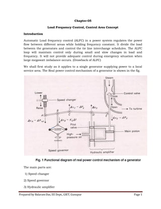
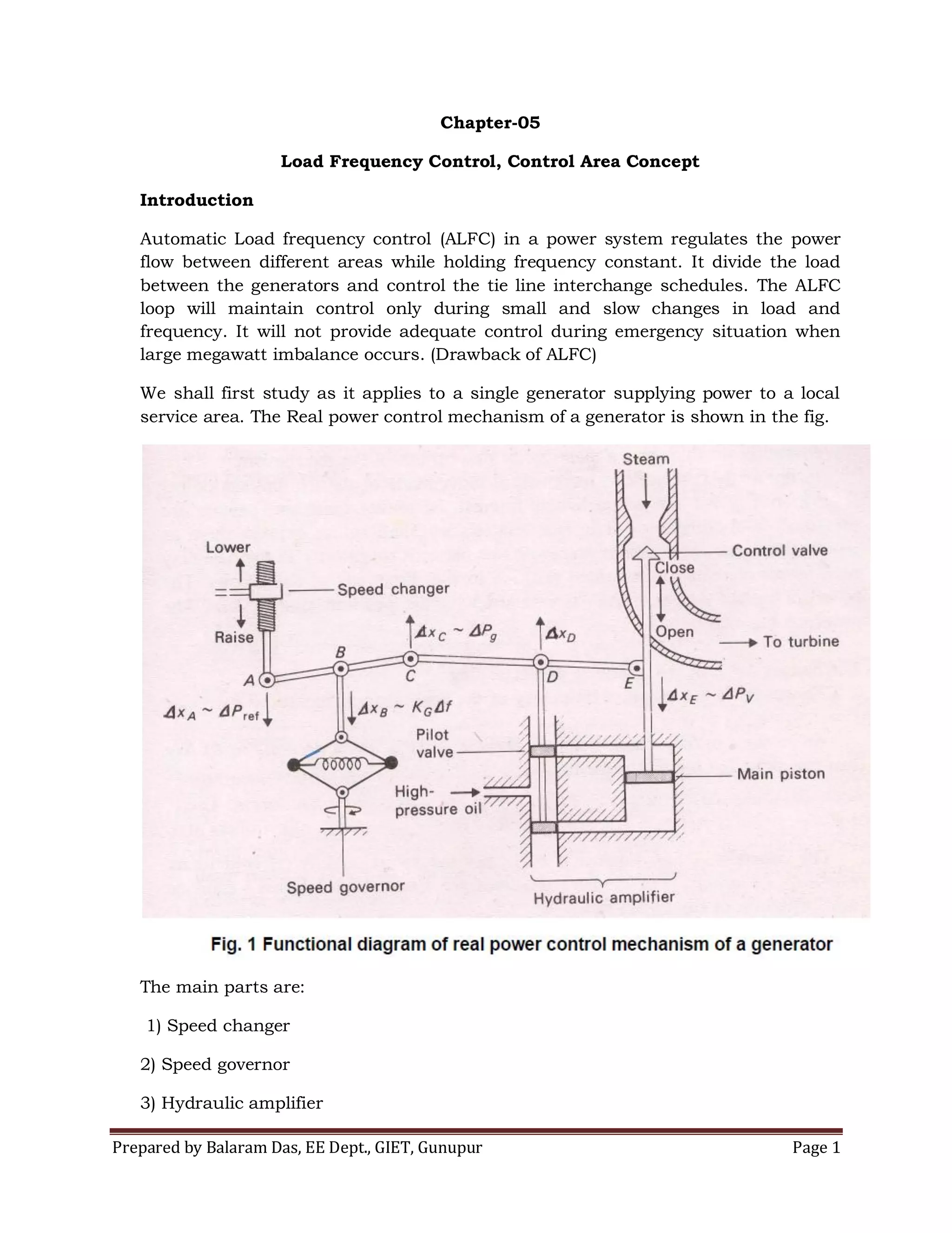
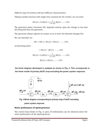
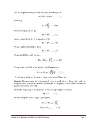
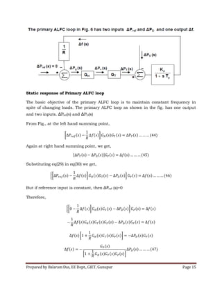
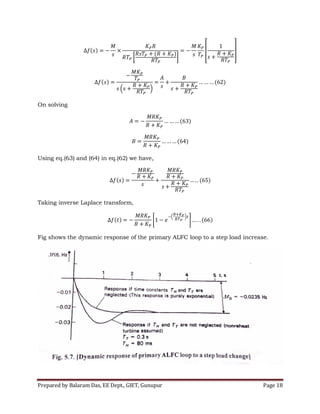
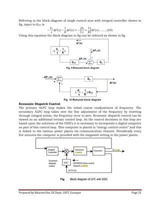
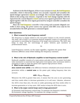
The document discusses Automatic Load Frequency Control (ALFC) in power systems, describing its operation to regulate power distribution between generators while maintaining frequency stability during small load and frequency changes. It outlines the components involved, such as speed governors and hydraulic amplifiers, and explains the dynamic and static responses of control loops in managing load frequency. Additionally, it addresses the need for secondary and tertiary control loops to fine-tune frequency adjustments and the role of area control error in balancing generation within a control area.
![Prepared by Balaram Das, EE Dept., GIET, Gunupur Page 12
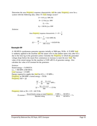
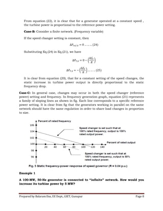
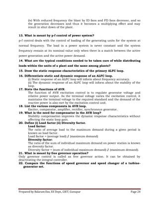
1. A 300 MW turbo generator has a speed regulation of 0.045pu on its own rated
capacity as base. Determine the increase in power output when the frequency
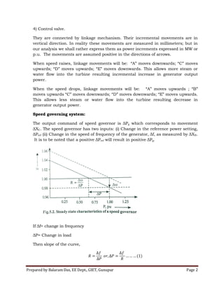
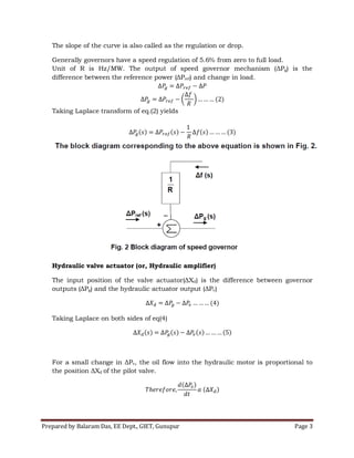
drops from normal 50Hz to a steady state value of 49.95 Hz. (2015) [5]
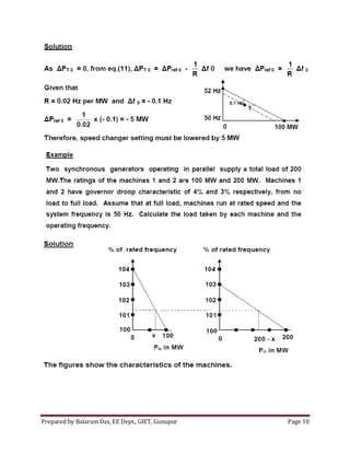
Solution:
Given the generator power, = 100 MW
Speed regulation = 0.045 pu.
Drop in frequency, Δf = -0.05Hz
Increase in turbine power = ?
Regulation parameter,
Increase in turbine power at the frequency drop of -0.05Hz
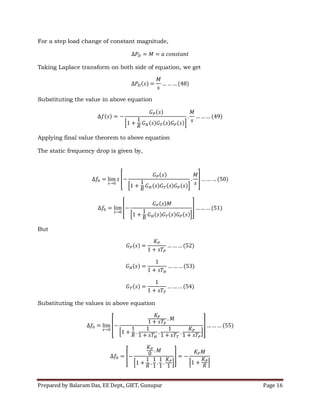
Closing the ALFC Loop
The “old” load is a function of voltage magnitude and frequency. The old area load
depends on the frequency given by
For area power balance, the increase in turbine power is equal to the sum of old and
new load changes plus the rate of change of kinetic energy.
Therefore area power balance is given by
Turbine power = old load change + new load change + rate of change of kinetic energy
If Δf = change in frequency relative to f0
f0 = frequency at normal state
The new frequency, f = f0 + Δf
Substituting the value of f, we get](https://image.slidesharecdn.com/automaticloadfrequencycontrol-180503124713/85/Automatic-load-frequency-control-12-320.jpg)
![Prepared by Balaram Das, EE Dept., GIET, Gunupur Page 27
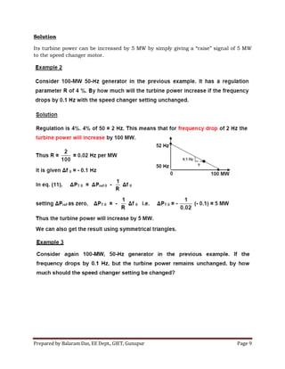
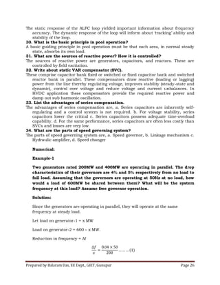
From equation(1),
From equation(2),
Comparing equation (2) and (3), we have
Therefore load on generator-1 is 231 MW
Load on generator-2 is 600-x = 600-231 = 369MW
System frequency =
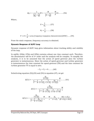
Example-2:
Two generators rated with 221MW and 429MW are operating in Parallel. The
drop characteristics of their governors are 4.15% and 5.35% respectively
from no-load to full load. The speed changers are so set that the generators
operate at 50 Hz sharing the full load of 650MW in the ratio of their ratings.
If the load reduces to 550 MW, what will be the load shared by each
generator? Also find out the system frequency under this condition. 2016 [5]
Solution:
Since the generators are operating in parallel, they will operate at the same
frequency at steady load.
Let load on generator-1(221MW) = x MW
Load on generator-2(429MW) = 550 – x MW.
Reduction in frequency = Δf](https://image.slidesharecdn.com/automaticloadfrequencycontrol-180503124713/85/Automatic-load-frequency-control-27-320.jpg)