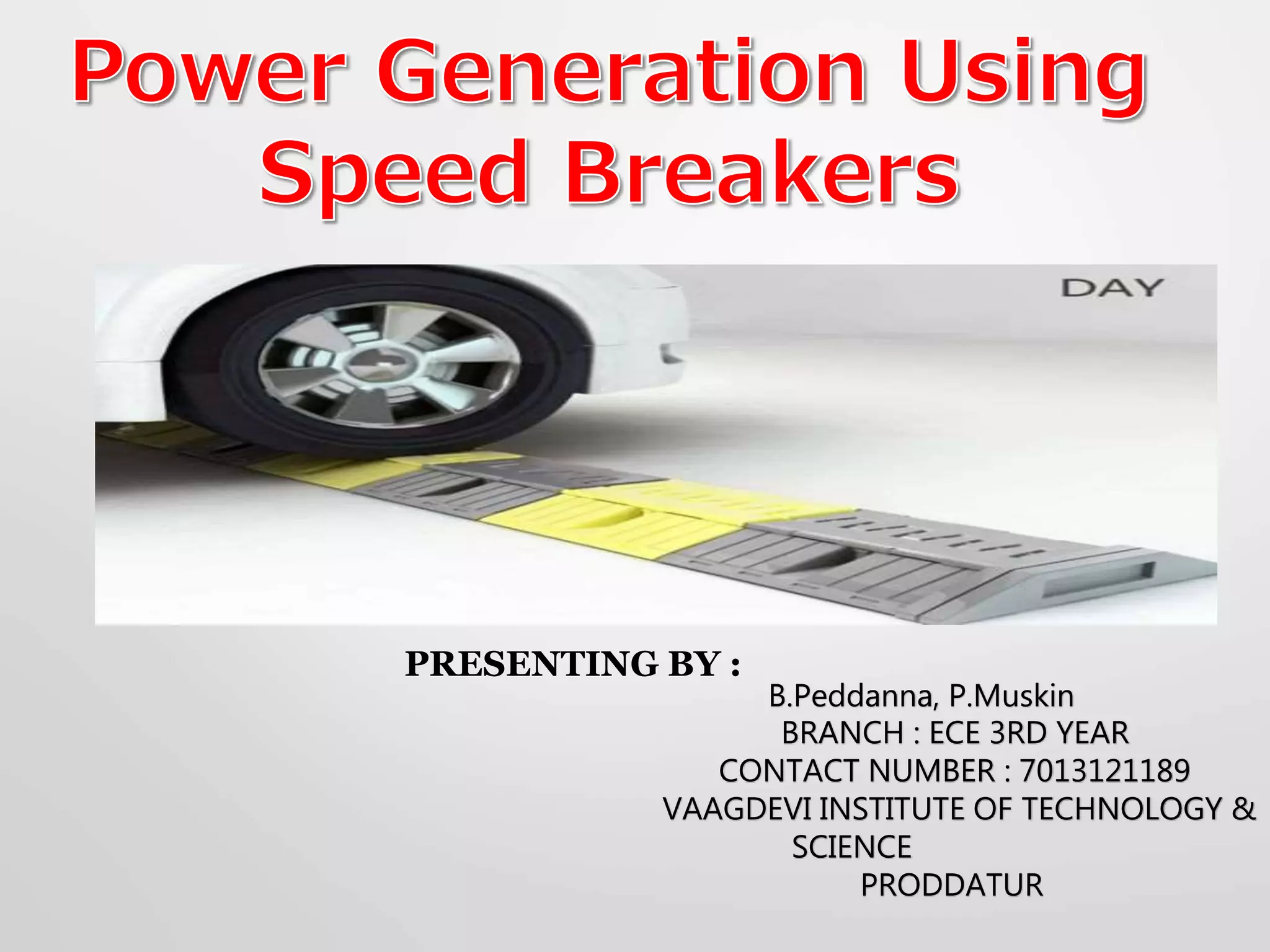
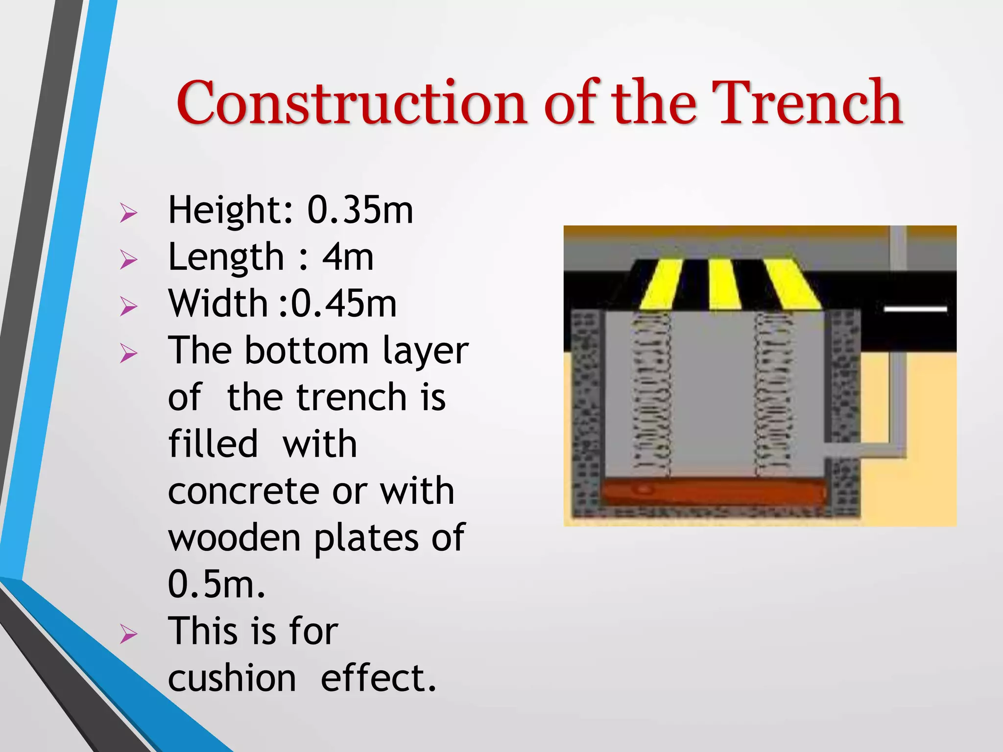
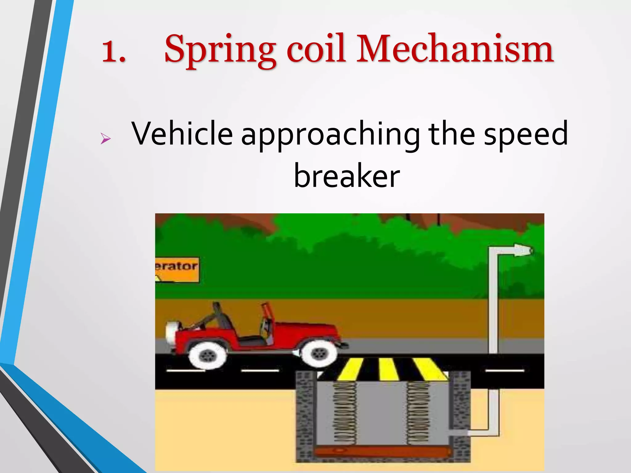
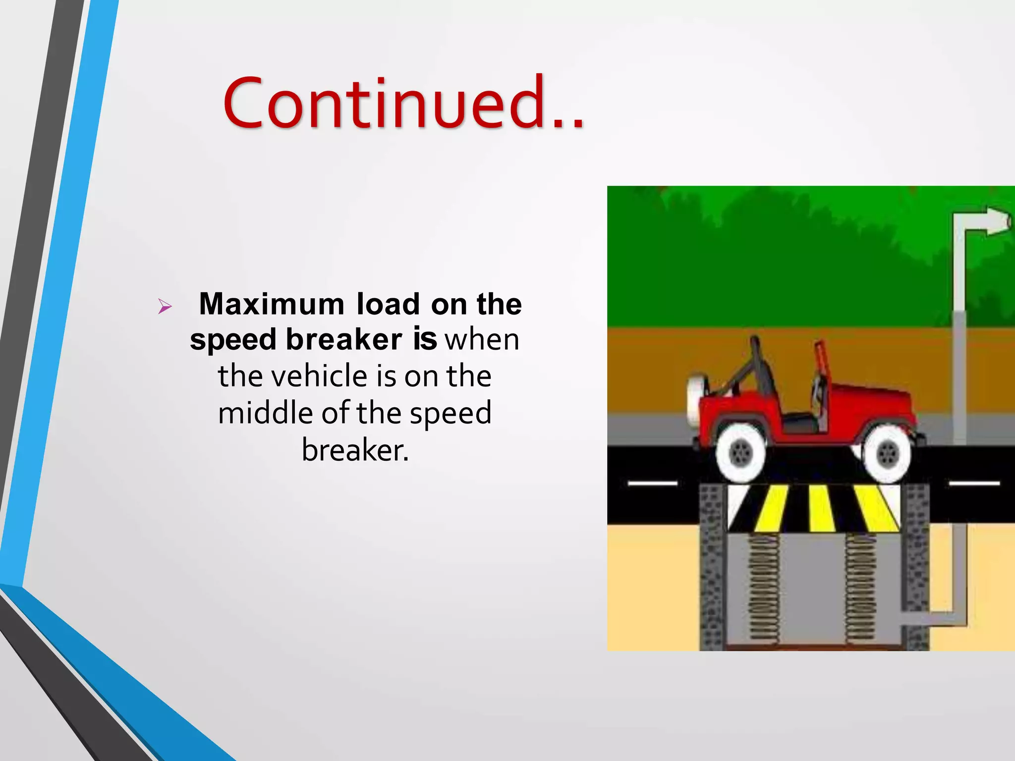
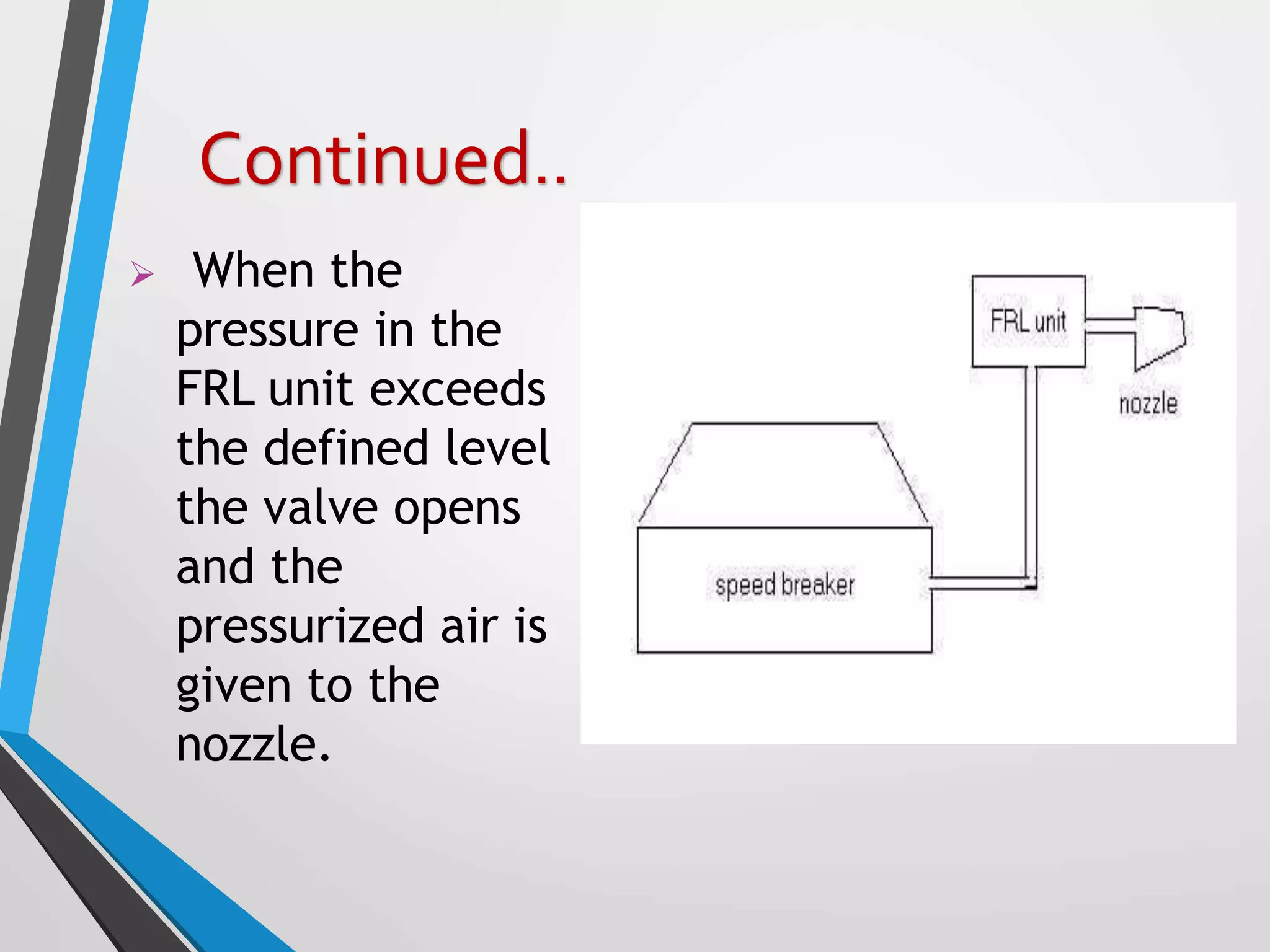
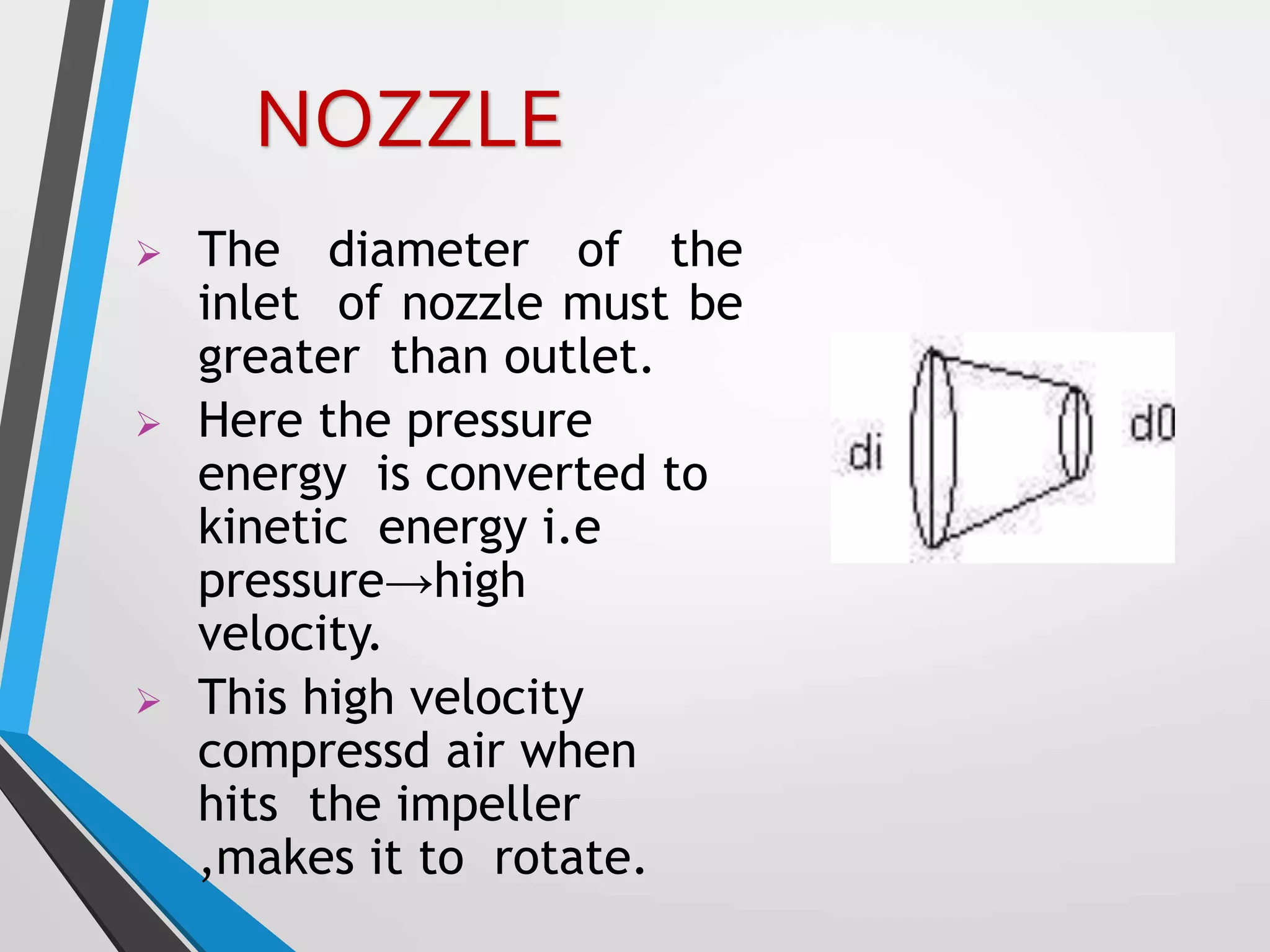
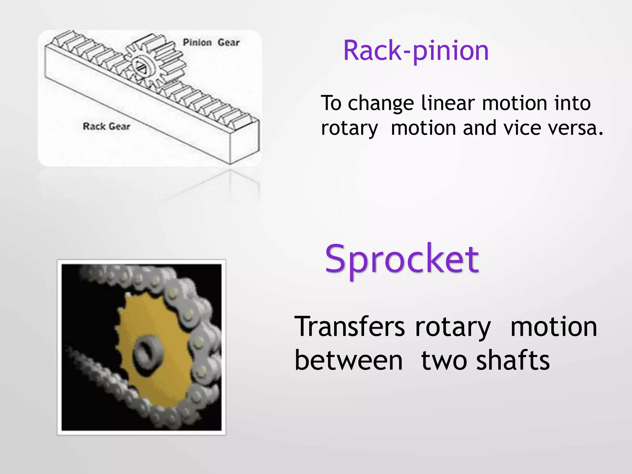
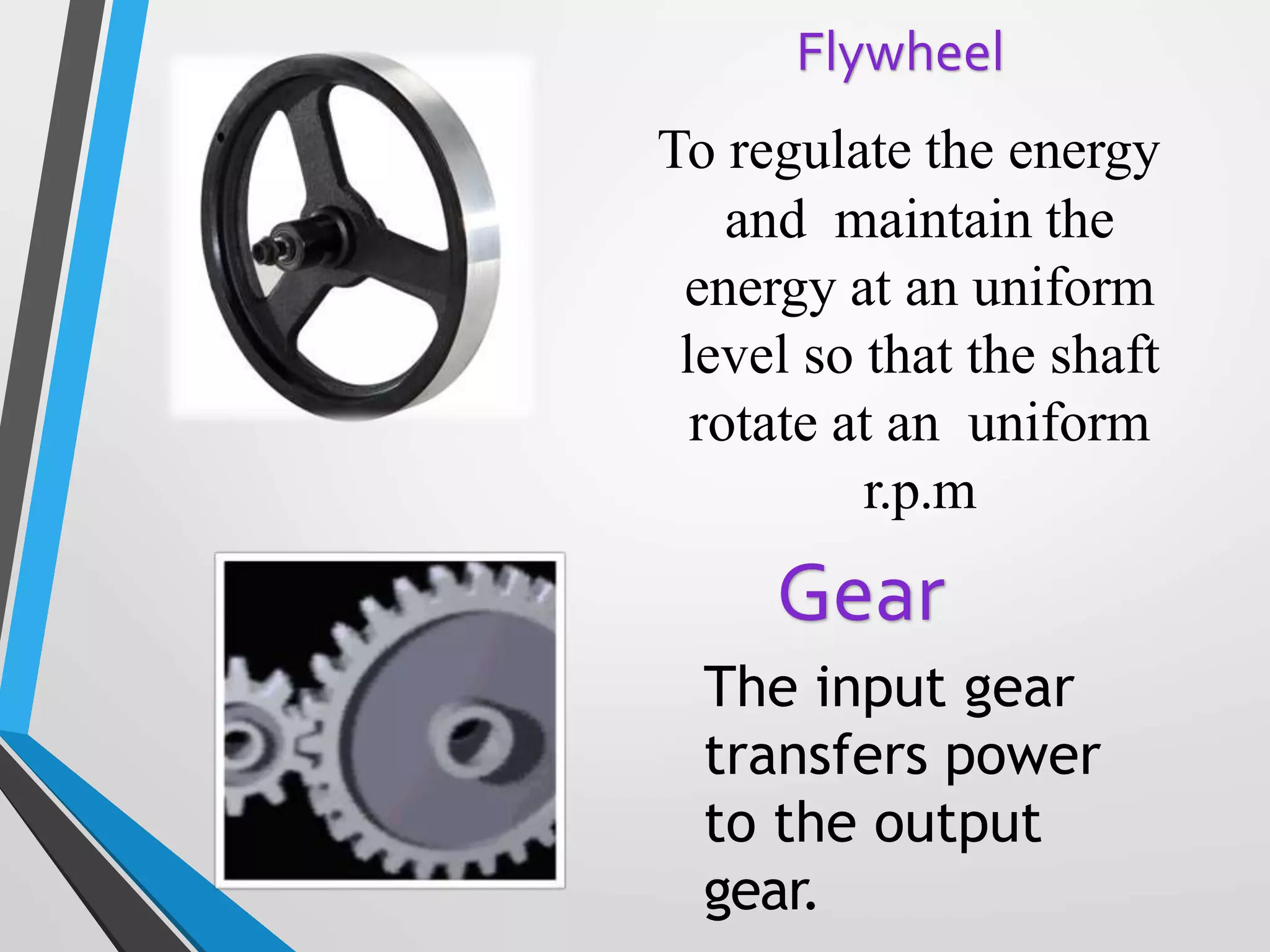
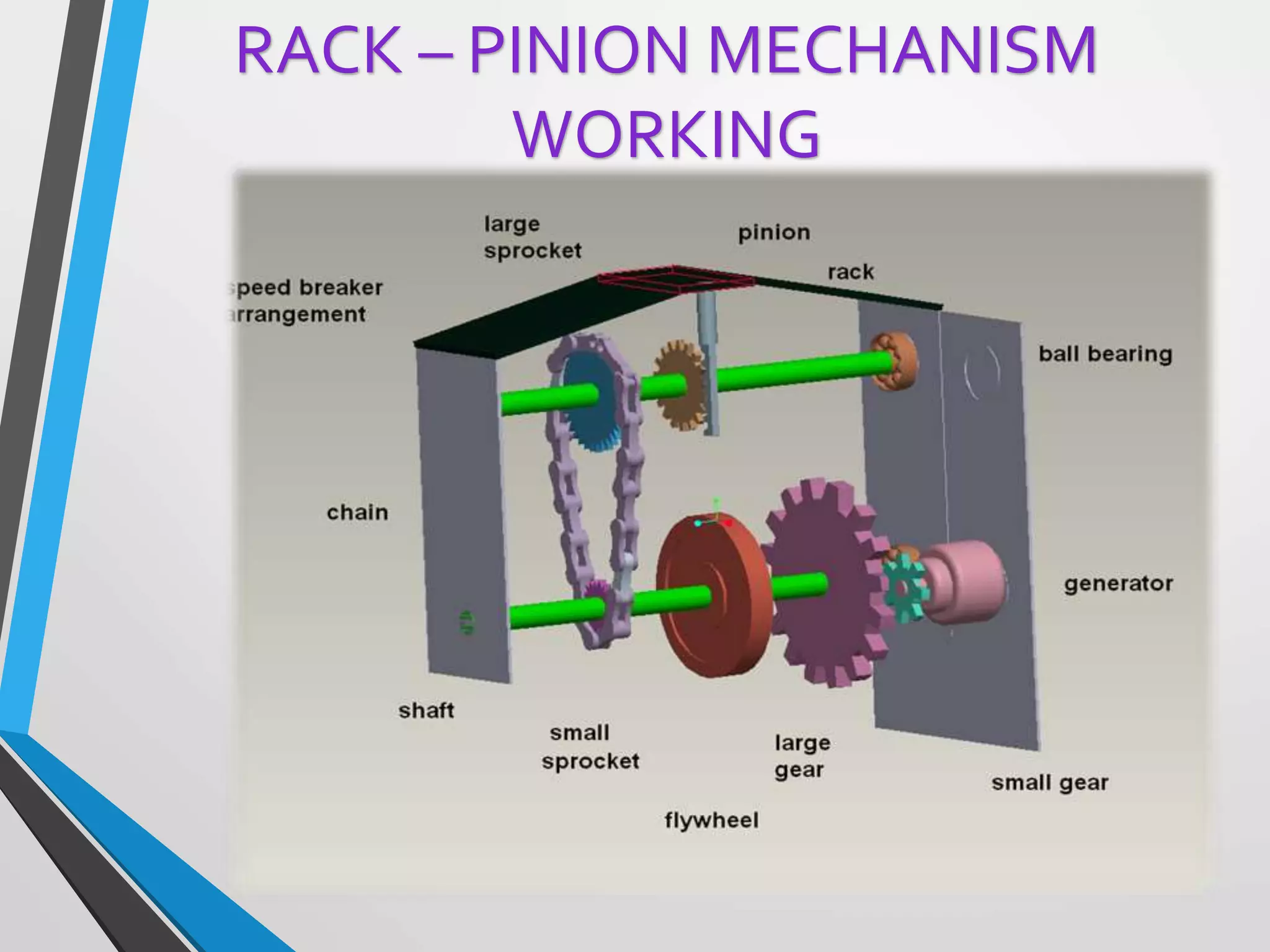
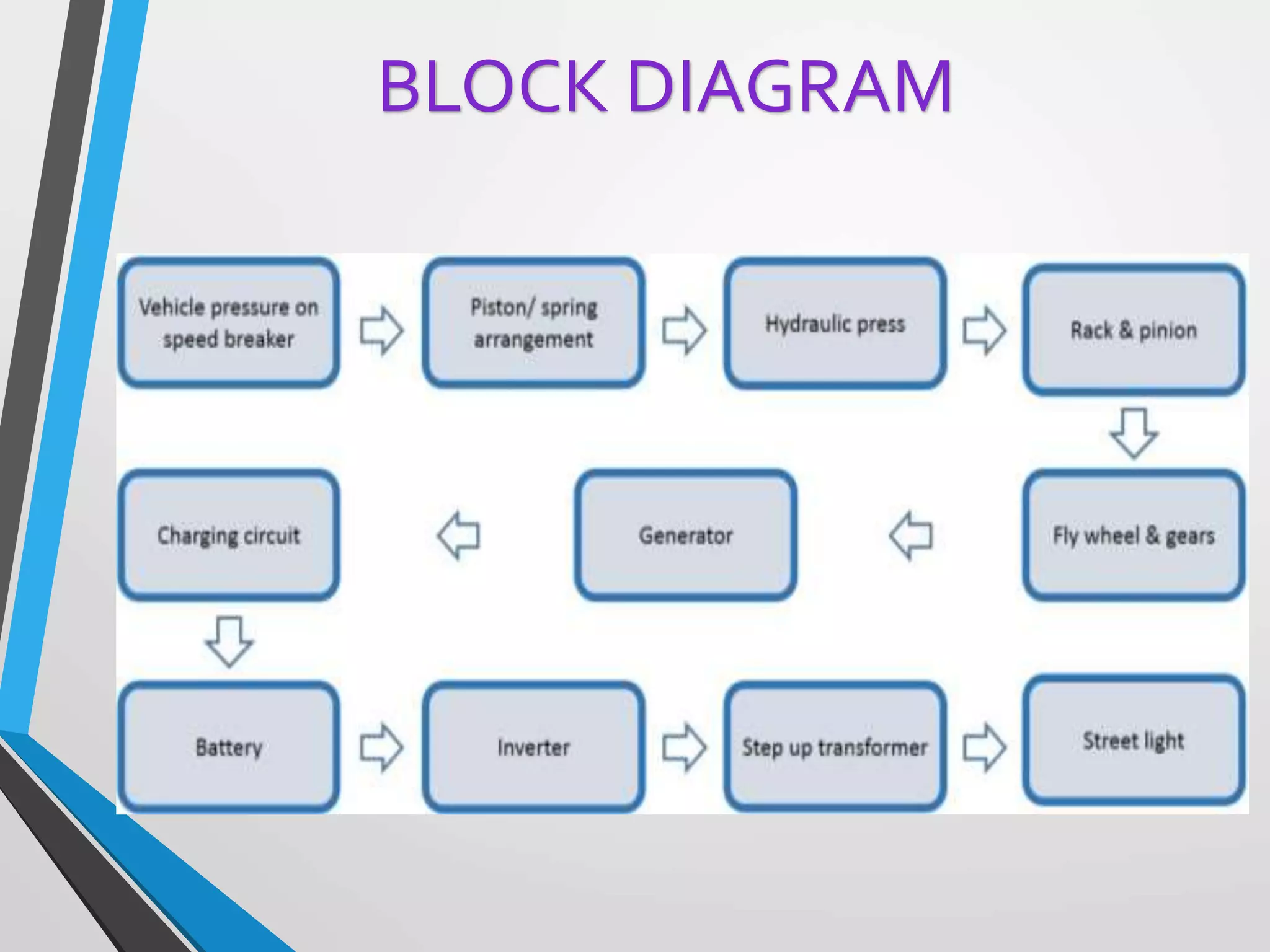
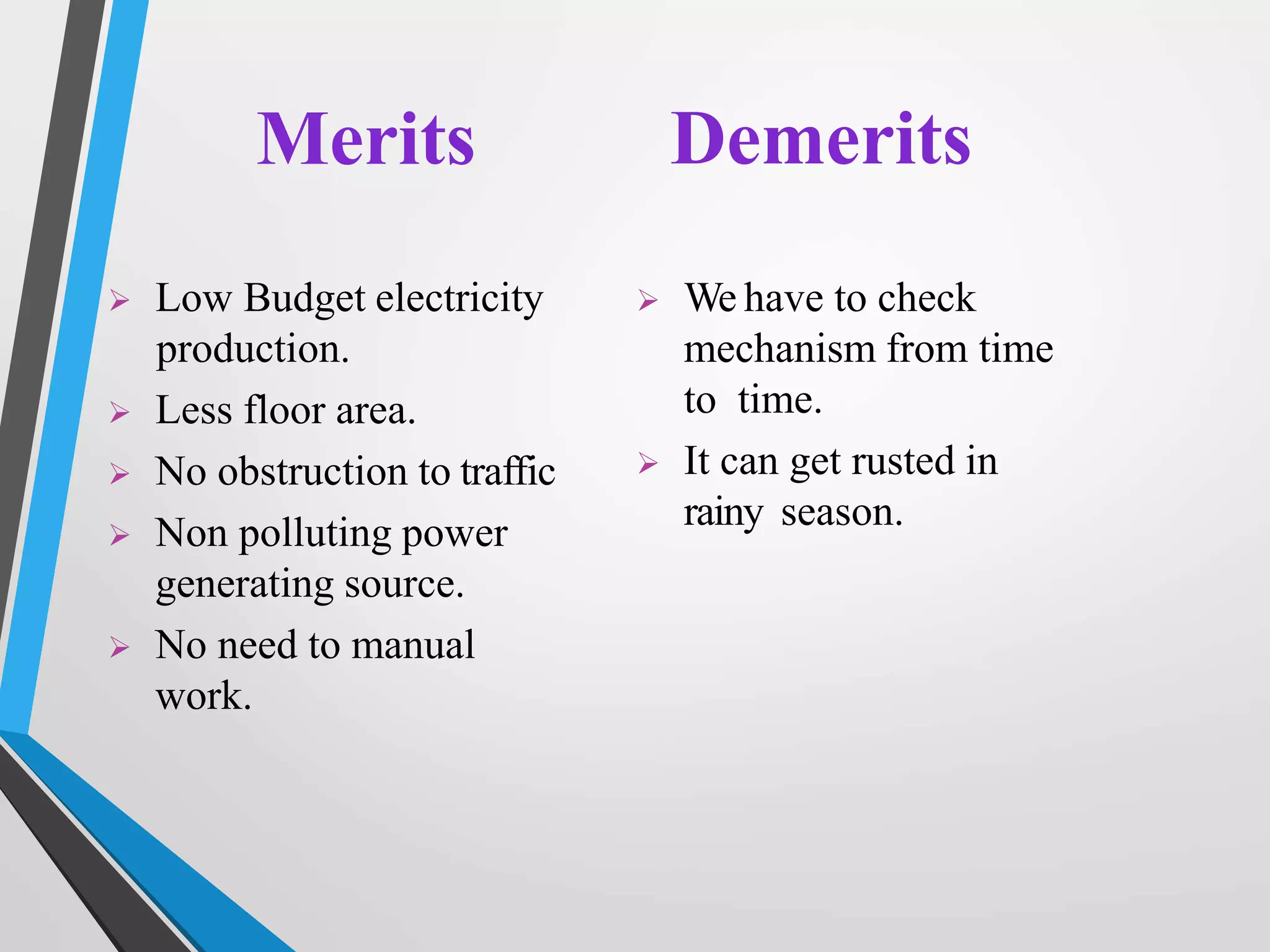
PRESENTING BY :
B.Peddanna, P.Muskin
BRANCH : ECE 3RD YEAR
CONTACT NUMBER : 7013121189
VAAGDEVI INSTITUTE OF TECHNOLOGY &
SCIENCE
PRODDATUR
 Introduction
 Different mechanisms
 Spring coil mechanism
 Rack pinion mechanism
 Merits and demerit
 scope and uses
 Conclusion
CONTENTS
 A large amount of energy is wasted at
the speed breakers through friction ,
every time a vehicle passes over it.
So electricity can be generated using the
vehicle weight (potential energy) as
input.
So, this is a small step to try to
improve this situation.
INTRODUCTION
POSSIBLE USING DIFFERENT MECHANISM
1.Spring coil mechanism.
2.Rack- pinion mechanism.
3.Crank-shaft mechanism.
4.Roller mechanism.
 Conversion of mechanical energy
to pneumatic energy.
which is converted to electrical
energy
Working principle
 The material used
in construction of
speed breakers is
steel.
 The shape of speed
breaker is
trapezoidal .
Design of the speed Breaker
 Here we are making the speed breaker of
vibrating type, when a vehicle crosses
the speed breaker, it gets pressed and
then it gets back to its original position.
 Dimensions of speed breaker:-
Height
Width
Length
: 0.2m
: 0.4m
: 4m
Construction of the speed Breaker
 Height: 0.35m
 Length : 4m
 Width :0.45m
 The bottom layer
of the trench is
filled with
concrete or with
wooden plates of
0.5m.
 This is for
cushion effect.
Construction of the Trench
 Vehicle approaching the speed
breaker
1. Spring coil Mechanism
 Maximum load on the
speed breaker is when
the vehicle is on the
middle of the speed
breaker.
Continued..
 When the
pressure in the
FRL unit exceeds
the defined level
the valve opens
and the
pressurized air is
given to the
nozzle.
Continued..
 The diameter of the
inlet of nozzle must be
greater than outlet.
 Here the pressure
energy is converted to
kinetic energy i.e
pressure→high
velocity.
 This high velocity
compressd air when
hits the impeller
,makes it to rotate.
NOZZLE
CONSISTS -
 Casing
 Runner and buckets
CASING-
 This is provided to safeguard device
against accidents.
IMPELLER
 It consists of a
circular disc on the
periphery of which
have number of
buckets evenly
spaced are fixed.
Each bucket is
divided in to 2
symmetrical parts by
a dividing wall is
know as splitter.
 When the air strikes
the runner ,it
rotates &
continues rotation
due to inertia.
RUNNER
 An electrical generator is a machine
which converts mechanical energy into
electrical energy.
 The output of the alternator is used to
light the street lights & is rectified &
stored in batteries.
ALTERNATOR
The various machine elements used in the
construction of power hump are
i. RACK-PINION
ii. SPROCKETS
iii. GEARS
iv. FLY WHEEL
v. SHAFT
vi. ELECTRIC GENERATOR
2.RACK PINION MECHANISM:
Sprocket
Transfers rotary motion
between two shafts
Rack-pinion
To change linear motion into
rotary motion and vice versa.
To regulate the energy
and maintain the
energy at an uniform
level so that the shaft
rotate at an uniform
r.p.m
Flywheel
Gear
The input gear
transfers power
to the output
gear.
RACK – PINION MECHANISM
WORKING
BLOCK DIAGRAM
Merits Demerits
 Low Budget electricity
production.
 Less floor area.
 No obstruction to traffic
 Non polluting power
generating source.
 No need to manual
work.
 We have to check
mechanism from time
to time.
 It can get rusted in
rainy season.
.
Future scope:
 Suitable at parking of multiplexes, malls, toll
booths, signals, etc.
 Uses: Charging batteries and using them to
light up the streets, etc.
 Such speed breakers can be designed for
heavy vehicles, thus increasing input torque
and ultimately output of generator.
 More suitable and compact mechanisms to
enhance efficiency.
 It can be implemented at metropolitan cities,
So that more electric power is produced.
 Arrangement of whole setup is easier and it
is eco friendly
 The stored electricity could satisfy the daily
requirement of electric power.
CONCLUSION
Power generation using speed breakers

Power generation using speed breakers

  • 1.
    PRESENTING BY : B.Peddanna,P.Muskin BRANCH : ECE 3RD YEAR CONTACT NUMBER : 7013121189 VAAGDEVI INSTITUTE OF TECHNOLOGY & SCIENCE PRODDATUR
  • 2.
     Introduction  Differentmechanisms  Spring coil mechanism  Rack pinion mechanism  Merits and demerit  scope and uses  Conclusion CONTENTS
  • 3.
     A largeamount of energy is wasted at the speed breakers through friction , every time a vehicle passes over it. So electricity can be generated using the vehicle weight (potential energy) as input. So, this is a small step to try to improve this situation. INTRODUCTION
  • 4.
    POSSIBLE USING DIFFERENTMECHANISM 1.Spring coil mechanism. 2.Rack- pinion mechanism. 3.Crank-shaft mechanism. 4.Roller mechanism.
  • 5.
     Conversion ofmechanical energy to pneumatic energy. which is converted to electrical energy Working principle
  • 6.
     The materialused in construction of speed breakers is steel.  The shape of speed breaker is trapezoidal . Design of the speed Breaker
  • 7.
     Here weare making the speed breaker of vibrating type, when a vehicle crosses the speed breaker, it gets pressed and then it gets back to its original position.  Dimensions of speed breaker:- Height Width Length : 0.2m : 0.4m : 4m Construction of the speed Breaker
  • 8.
     Height: 0.35m Length : 4m  Width :0.45m  The bottom layer of the trench is filled with concrete or with wooden plates of 0.5m.  This is for cushion effect. Construction of the Trench
  • 9.
     Vehicle approachingthe speed breaker 1. Spring coil Mechanism
  • 10.
     Maximum loadon the speed breaker is when the vehicle is on the middle of the speed breaker. Continued..
  • 11.
     When the pressurein the FRL unit exceeds the defined level the valve opens and the pressurized air is given to the nozzle. Continued..
  • 12.
     The diameterof the inlet of nozzle must be greater than outlet.  Here the pressure energy is converted to kinetic energy i.e pressure→high velocity.  This high velocity compressd air when hits the impeller ,makes it to rotate. NOZZLE
  • 13.
    CONSISTS -  Casing Runner and buckets CASING-  This is provided to safeguard device against accidents. IMPELLER
  • 14.
     It consistsof a circular disc on the periphery of which have number of buckets evenly spaced are fixed. Each bucket is divided in to 2 symmetrical parts by a dividing wall is know as splitter.  When the air strikes the runner ,it rotates & continues rotation due to inertia. RUNNER
  • 15.
     An electricalgenerator is a machine which converts mechanical energy into electrical energy.  The output of the alternator is used to light the street lights & is rectified & stored in batteries. ALTERNATOR
  • 16.
    The various machineelements used in the construction of power hump are i. RACK-PINION ii. SPROCKETS iii. GEARS iv. FLY WHEEL v. SHAFT vi. ELECTRIC GENERATOR 2.RACK PINION MECHANISM:
  • 17.
    Sprocket Transfers rotary motion betweentwo shafts Rack-pinion To change linear motion into rotary motion and vice versa.
  • 18.
    To regulate theenergy and maintain the energy at an uniform level so that the shaft rotate at an uniform r.p.m Flywheel Gear The input gear transfers power to the output gear.
  • 19.
    RACK – PINIONMECHANISM WORKING
  • 20.
  • 21.
    Merits Demerits  LowBudget electricity production.  Less floor area.  No obstruction to traffic  Non polluting power generating source.  No need to manual work.  We have to check mechanism from time to time.  It can get rusted in rainy season.
  • 22.
    . Future scope:  Suitableat parking of multiplexes, malls, toll booths, signals, etc.  Uses: Charging batteries and using them to light up the streets, etc.  Such speed breakers can be designed for heavy vehicles, thus increasing input torque and ultimately output of generator.  More suitable and compact mechanisms to enhance efficiency.
  • 23.
     It canbe implemented at metropolitan cities, So that more electric power is produced.  Arrangement of whole setup is easier and it is eco friendly  The stored electricity could satisfy the daily requirement of electric power. CONCLUSION