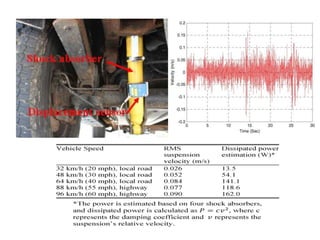
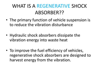
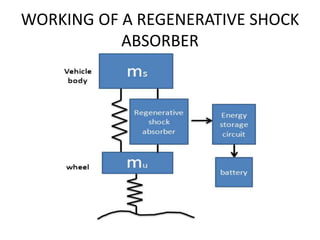
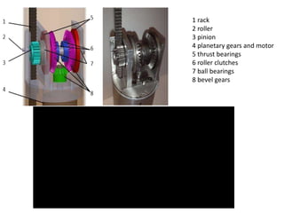
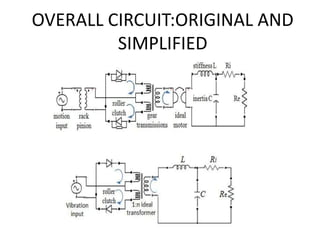
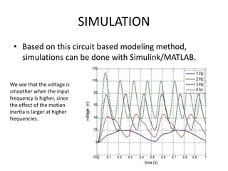
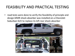
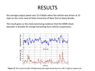
REGENERATIVE SHOCK
ABSORBER
Presented by:
NISHANT SARASWAT
USN:1DS11ME060
8TH SEM,SECTION-B
Presented on:
MARCH 4TH 2015
DEPARTMENT OF MECHANICAL ENGINEERING
dayananda sagar college of engineering
INTRODUCTION
• WHY THE NEED??
IN UNITED STATES ALONE,70% OF THE TOTAL
OIL CONSUMPTION IS UTILISED IN
TRANSPORTATION.
USEFUL: 10-16% OF THE TOTAL FUEL ENERGY !!
IMPROVEMENT OF FUEL EFFICIENCY
WHAT IS A REGENERATIVE SHOCK
ABSORBER??
• The primary function of vehicle suspension is
to reduce the vibration disturbance
• Hydraulic shock absorbers dissipate the
vibration energy into waste heat
• To improve the fuel efficiency of vehicles,
regenerative shock absorbers are designed to
harvest energy from the vibration.
WORKING OF A REGENERATIVE SHOCK
ABSORBER
REG. SHOCK
ABSORBERS
LINEAR TYPE
ROTARY
TYPE
• LINEAR TYPE:
utilize the relative motion
between magnetic field and
coils to directly generate
power based on Faraday’s
law of electromagnetic
induction
• ROTARY TYPE:
The rotary shock absorbers
transfer linear motion of
suspension vibration to rotary
motion to drive permanent
magnetic dc generators.
ROTARY TYPE REG. SHOCK ABSORBERS
• rotary shock absorbers are capable of generating more
power and getting a larger damping coefficient for the
given space
• Convert linear vibrations to rotary via 2 mechanisms:
>ball-screw mechanism
>rack and pinion mechanism
• Ball screw mechanism yield in lower efficiency at high
frequencies of vibration
• Preferred: rack and pinion mechanism
DESIGN PRINCIPLE
ADDITION OF MMR
• MMR = MECHANICAL MOTION RECTIFIER
• Analogous to a sine wave rectifier in an electric circuit
• A “motion rectifier” is created to “commutate” oscillatory
motion
• Converts 2-directional linear movement to a 1 direction
rotary movement
• The key components of “motion rectifier” are two one-way
roller clutches that transmit rotation only in one direction
and dive the motion in two different routes
• As a result, the shaft of the motor and planetary gear will
move always in one direction.
1 rack
2 roller
3 pinion
4 planetary gears and motor
5 thrust bearings
6 roller clutches
7 ball bearings
8 bevel gears
OVERALL CIRCUIT:ORIGINAL AND
SIMPLIFIED
SIMULATION
• Based on this circuit based modeling method,
simulations can be done with Simulink/MATLAB.
We see that the voltage is
smoother when the input
frequency is higher, since
the effect of the motion
inertia is larger at higher
frequencies.
FEASIBILITY AND PRACTICAL TESTING
• road tests were done to verify the feasibility of principle and
design.MMR shock absorber was installed on a Chevrolet
Suburban SUV to replace its left rear shock absorber
RESULTS
the average output power was 15.4 Watts when the vehicle was driven at 15
mph on the circle road of State University of New York at Stony Brooks.
The result gives us the most convincing evidence that the MMR shock
absorber is feasible for energy harvesting from vehicle suspensions.
CONCLUSLION
• A rack–pinion-based electromagnetic regenerative
shock absorber is developed and tested, which can
generate electric power from the road-induced
suspension vibration of vehicles.
• Road tests were carried out to verify the performance
of the new designed regenerative shock absorber. The
experiment results indicate that the generated voltage
reflects the road irregularities well
• Mechanical motion rectifier was adopted for enhanced
efficiency and reliability
REFERENCES
• Electromagnetic Energy-Harvesting Shock Absorbers: Design,
Modeling, and Road Tests by Zhongjie Li, Lei Zuo, George Luhrs,
Liangjun Lin, and Yi-xian Qin
IEEE TRANSACTIONS ON VEHICULAR TECHNOLOGY, VOL. 62, NO. 3,
MARCH 2013
• Efatpenah K Beno JH and Nichols SP 2000 Energy requirements of a
passive and an electromechanical active suspension system Vehicle
System Dynamics 34, 437-458
• Experimental Study of Damping and Energy Regeneration
Characteristics of a Hydraulic Electromagnetic Shock Absorber by
Zhigang Fang, Xuexun Guo, Lin Xu, and Han Zhang
Hindawi Publishing Corporation Advances in Mechanical Engineering
Volume 2013, Article ID 943528, 9 pages
http://dx.doi.org/10.1155/2013/943528

REGENERATIVE SHOCK ABSORBER

  • 1.
    REGENERATIVE SHOCK ABSORBER Presented by: NISHANTSARASWAT USN:1DS11ME060 8TH SEM,SECTION-B Presented on: MARCH 4TH 2015 DEPARTMENT OF MECHANICAL ENGINEERING dayananda sagar college of engineering
  • 2.
    INTRODUCTION • WHY THENEED?? IN UNITED STATES ALONE,70% OF THE TOTAL OIL CONSUMPTION IS UTILISED IN TRANSPORTATION. USEFUL: 10-16% OF THE TOTAL FUEL ENERGY !! IMPROVEMENT OF FUEL EFFICIENCY
  • 4.
    WHAT IS AREGENERATIVE SHOCK ABSORBER?? • The primary function of vehicle suspension is to reduce the vibration disturbance • Hydraulic shock absorbers dissipate the vibration energy into waste heat • To improve the fuel efficiency of vehicles, regenerative shock absorbers are designed to harvest energy from the vibration.
  • 5.
    WORKING OF AREGENERATIVE SHOCK ABSORBER
  • 6.
    REG. SHOCK ABSORBERS LINEAR TYPE ROTARY TYPE •LINEAR TYPE: utilize the relative motion between magnetic field and coils to directly generate power based on Faraday’s law of electromagnetic induction • ROTARY TYPE: The rotary shock absorbers transfer linear motion of suspension vibration to rotary motion to drive permanent magnetic dc generators.
  • 7.
    ROTARY TYPE REG.SHOCK ABSORBERS • rotary shock absorbers are capable of generating more power and getting a larger damping coefficient for the given space • Convert linear vibrations to rotary via 2 mechanisms: >ball-screw mechanism >rack and pinion mechanism • Ball screw mechanism yield in lower efficiency at high frequencies of vibration • Preferred: rack and pinion mechanism
  • 8.
  • 9.
    ADDITION OF MMR •MMR = MECHANICAL MOTION RECTIFIER • Analogous to a sine wave rectifier in an electric circuit • A “motion rectifier” is created to “commutate” oscillatory motion • Converts 2-directional linear movement to a 1 direction rotary movement • The key components of “motion rectifier” are two one-way roller clutches that transmit rotation only in one direction and dive the motion in two different routes • As a result, the shaft of the motor and planetary gear will move always in one direction.
  • 10.
    1 rack 2 roller 3pinion 4 planetary gears and motor 5 thrust bearings 6 roller clutches 7 ball bearings 8 bevel gears
  • 11.
  • 12.
    SIMULATION • Based onthis circuit based modeling method, simulations can be done with Simulink/MATLAB. We see that the voltage is smoother when the input frequency is higher, since the effect of the motion inertia is larger at higher frequencies.
  • 13.
    FEASIBILITY AND PRACTICALTESTING • road tests were done to verify the feasibility of principle and design.MMR shock absorber was installed on a Chevrolet Suburban SUV to replace its left rear shock absorber
  • 14.
    RESULTS the average outputpower was 15.4 Watts when the vehicle was driven at 15 mph on the circle road of State University of New York at Stony Brooks. The result gives us the most convincing evidence that the MMR shock absorber is feasible for energy harvesting from vehicle suspensions.
  • 15.
    CONCLUSLION • A rack–pinion-basedelectromagnetic regenerative shock absorber is developed and tested, which can generate electric power from the road-induced suspension vibration of vehicles. • Road tests were carried out to verify the performance of the new designed regenerative shock absorber. The experiment results indicate that the generated voltage reflects the road irregularities well • Mechanical motion rectifier was adopted for enhanced efficiency and reliability
  • 16.
    REFERENCES • Electromagnetic Energy-HarvestingShock Absorbers: Design, Modeling, and Road Tests by Zhongjie Li, Lei Zuo, George Luhrs, Liangjun Lin, and Yi-xian Qin IEEE TRANSACTIONS ON VEHICULAR TECHNOLOGY, VOL. 62, NO. 3, MARCH 2013 • Efatpenah K Beno JH and Nichols SP 2000 Energy requirements of a passive and an electromechanical active suspension system Vehicle System Dynamics 34, 437-458 • Experimental Study of Damping and Energy Regeneration Characteristics of a Hydraulic Electromagnetic Shock Absorber by Zhigang Fang, Xuexun Guo, Lin Xu, and Han Zhang Hindawi Publishing Corporation Advances in Mechanical Engineering Volume 2013, Article ID 943528, 9 pages http://dx.doi.org/10.1155/2013/943528