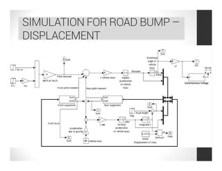
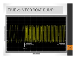
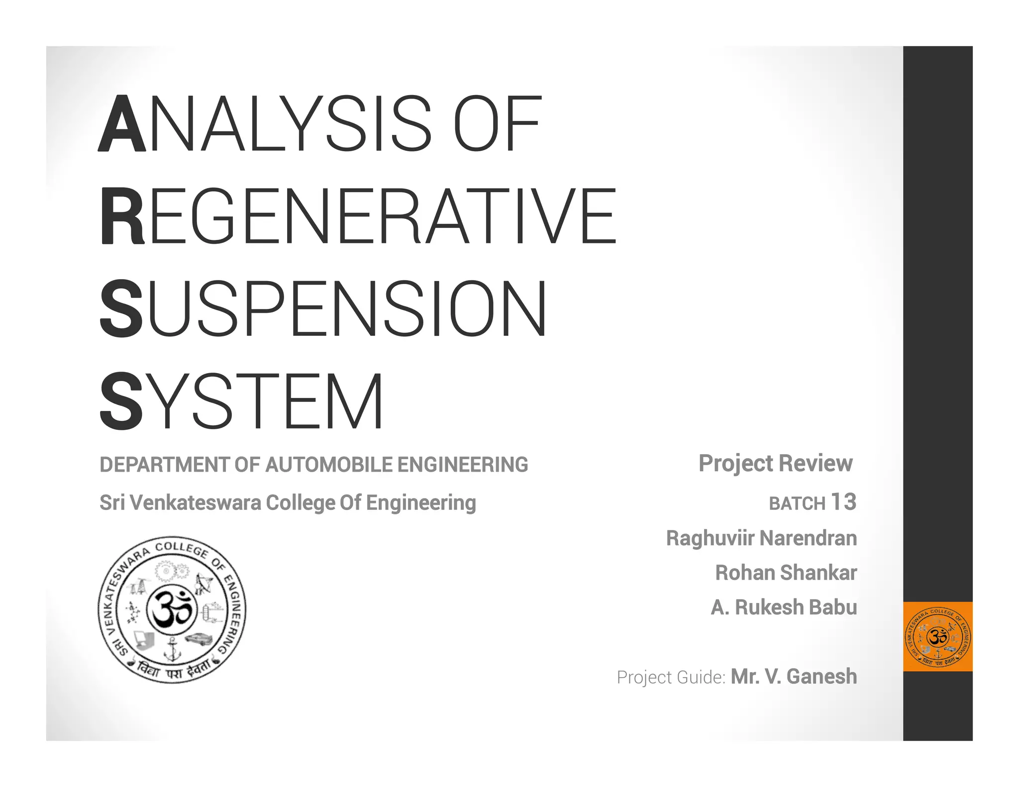
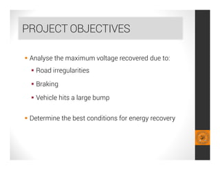
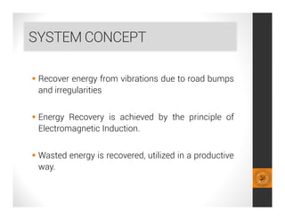
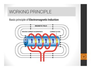
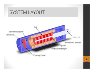
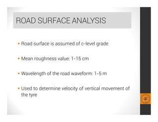
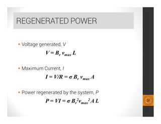
This document analyzes a regenerative suspension system that recovers wasted energy from vehicle vibrations and road irregularities using electromagnetic induction. The objectives are to determine the maximum voltage recovered from road bumps, braking, and large bumps, and the best conditions for energy recovery. It describes the system concept of recovering energy from vertical suspension movements through coils and magnets. Simulation results show the instantaneous voltage generated from different velocities and road bump displacements. The system aims to conserve normally wasted vibration energy.
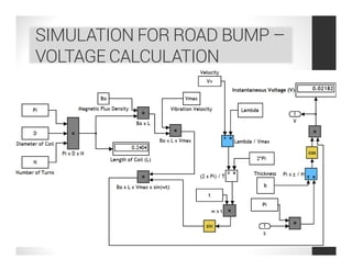
![INSTANTANEOUS VOLTAGE (V)
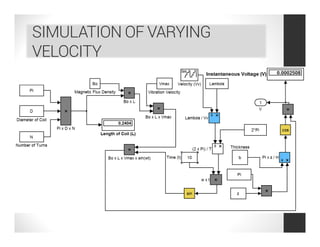
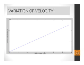
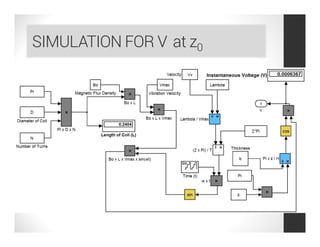
instantaneous voltage of one coil centred at z0 is
V = B0 L cos { π [z0 – (vmax/ω) cos ωt]/H} vmax sinωt](https://image.slidesharecdn.com/121f9b0b-165f-4cfd-8bdc-b033b6265eb0-161123182304/85/Regenerative-Suspension-System-Project-Review-Compatibility-Mode-13-320.jpg)
![INSTANTANEOUS VOLTAGE
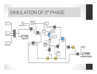
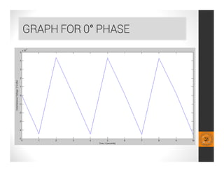
In order to account for practicality, we consider,
0° phase of the coil,
V = B0 L cos {π [(vmax/ω) cosωt]/b} vmax sinωt
90° phase
V = B0 L sin {π [(vmax/ω) cosωt]/b} vmax sinωt](https://image.slidesharecdn.com/121f9b0b-165f-4cfd-8bdc-b033b6265eb0-161123182304/85/Regenerative-Suspension-System-Project-Review-Compatibility-Mode-15-320.jpg)