Downloaded 1,286 times
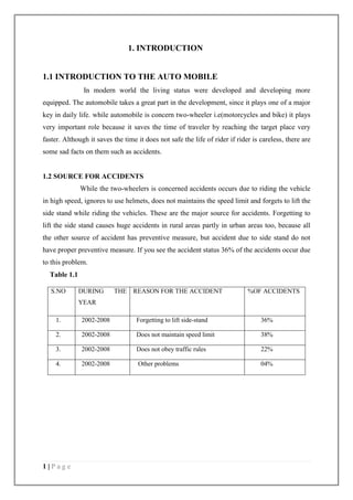
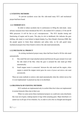


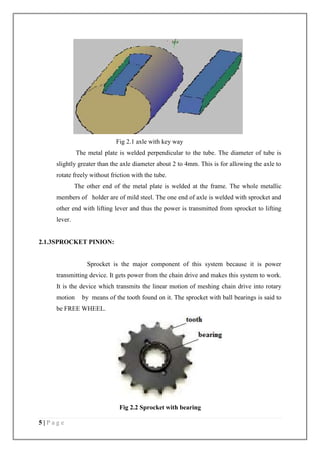


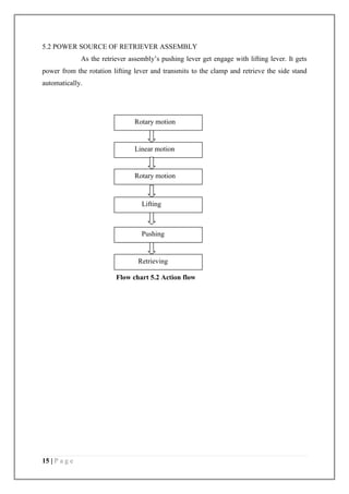


This document provides an introduction and overview of a proposed "sprocket-side stand retrieve system" for motorcycles. It discusses that 36% of motorcycle accidents are caused by riders forgetting to lift the side stand. Existing solutions like ECU indicators and mechanical retrieval systems have drawbacks. The proposed system uses a sprocket connected to the drive chain to power a lifting lever mechanism. When the engine is started, the sprocket would rotate and automatically lift the side stand via engaging the lifting lever with a pushing lever attached to the side stand. Detailed specifications and diagrams of the sprocket, axle, lifting lever, pushing lever, and other components are provided. The document concludes by discussing assembly of the system components.


