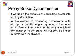
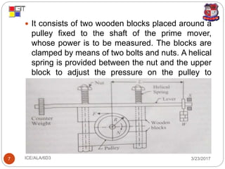
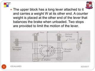
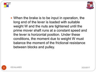
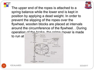
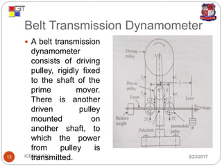
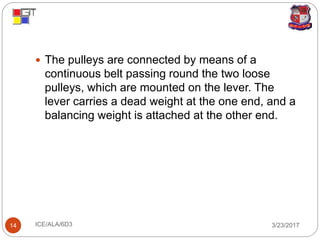
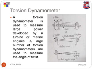
GANDHINAGAR INSTITUTE OF
TECHNOLOGY
INTERNAL COMBUSTION ENGINES
ACTIVE LEARNING ASSIGNMENT
DYNAMOMETERS
PREPARED BY
VADI RAKSHIT D (150123119055)
MECHANICAL 6
D3
Contents
3/23/2017ICE/ALA/6D32
 Dynamometers.
 Types of dynamometers.
 Absorption type dynamometers.
 Transmission type dynamometers.
Dynamometer
3/23/2017ICE/ALA/6D33
 Dynamometer is a device to measure the output (brake
power) of a prime mover. The power is measured by
applying the frictional torque by means of a brake. By
knowing the frictional torque, the power of the engine
can be calculated.
`
Types of Dynamometers
3/23/2017ICE/ALA/6D34
 Absorption Dynamometers
I. Prony Brake Dynamometers
II. Rope Brake Dynamometers
 Transmission Dynamometers
I. Belt Transmission Dynamometer
II. Torsion Dynamometer
Absorption Dynamometers
3/23/2017ICE/ALA/6D35
 In these types of dynamometers, the entire power
produced by the prime mover is absorbed by the
frictional resistance of the brake and is
transformed into heat, during the process of
measurement
 Examples of such dynamometers are
• Prony brake dynamometer.
• Rope brake dynamometer.
Prony Brake Dynamometer
3/23/2017ICE/ALA/6D36
 It works on the principle of converting power into
heat by dry friction.
 In this method of measuring horsepower is to
attempt to stop the engine by means of a brake
on the flywheel and measure the weight which an
arm attached to the brake will support, as it tries
to rotate with the flywheel.
3/23/2017ICE/ALA/6D37
 It consists of two wooden blocks placed around a
pulley fixed to the shaft of the prime mover,
whose power is to be measured. The blocks are
clamped by means of two bolts and nuts. A helical
spring is provided between the nut and the upper
block to adjust the pressure on the pulley to
control its speed.
3/23/2017ICE/ALA/6D38
 The upper block has a long lever attached to it
and carries a weight W at its other end. A counter
weight is placed at the other end of the lever that
balances the brake when unloaded. Two stops
are provided to limit the motion of the lever.
3/23/2017ICE/ALA/6D39
 When the brake is to be input in operation, the
long end of the lever is loaded with suitable
weight W and the nuts are tightened until the
prime mover shaft runs at a constant speed and
the lever is horizontal position. Under these
conditions, the moment due to weight W must
balance the moment of the frictional resistance
between blocks and pulley.
Rope Brake Dynamometer
3/23/2017ICE/ALA/6D310
 It consists of a number of turns of rope wound
around the rotating drum attached to the output
shaft. One side of rope is connected to a spring
balance and the other to a loading device.
 The power is absorbed in friction between the
rope and the drum. The drum therefore require
cooling.
 Rope brake is cheap and easily constructed.
 It is not very accurate because of changes in the
friction coefficient of the rope with temperature.
3/23/2017ICE/ALA/6D311
 The upper end of the ropes is attached to a
spring balance while the lower end is kept in
position by applying a dead weight. In order to
prevent the slipping of the ropes over the
flywheel, wooden blocks are placed at intervals
around the circumference of the flywheel. . During
operation of the brake, the prime mover is made
to run at constant speed.
Transmission Dynamometers
3/23/2017ICE/ALA/6D312
 In these dynamometers, the energy is used for
doing work. The power developed by the prime
mover is transmitted through the dynamometers
to some other machine where the power is
suitably measured.
 This type of dynamometer can be classified as
follows:
• Belt Transmission Dynamometer
• Torsion Dynamometer
Belt Transmission Dynamometer
3/23/2017ICE/ALA/6D313
 A belt transmission
dynamometer
consists of driving
pulley, rigidly fixed
to the shaft of the
prime mover.
There is another
driven pulley
mounted on
another shaft, to
which the power
from pulley is
transmitted.
3/23/2017ICE/ALA/6D314
 The pulleys are connected by means of a
continuous belt passing round the two loose
pulleys, which are mounted on the lever. The
lever carries a dead weight at the one end, and a
balancing weight is attached at the other end.
Torsion Dynamometer
3/23/2017ICE/ALA/6D315
 A torsion
dynamometer is
used to measure
large power
developed by a
turbine or marine
engines. A large
number of torsion
dynamometers are
used to measure
the angle of twist.
3/23/2017ICE/ALA/6D316

presentation on dynamometers

  • 1.
    GANDHINAGAR INSTITUTE OF TECHNOLOGY INTERNALCOMBUSTION ENGINES ACTIVE LEARNING ASSIGNMENT DYNAMOMETERS PREPARED BY VADI RAKSHIT D (150123119055) MECHANICAL 6 D3
  • 2.
    Contents 3/23/2017ICE/ALA/6D32  Dynamometers.  Typesof dynamometers.  Absorption type dynamometers.  Transmission type dynamometers.
  • 3.
    Dynamometer 3/23/2017ICE/ALA/6D33  Dynamometer isa device to measure the output (brake power) of a prime mover. The power is measured by applying the frictional torque by means of a brake. By knowing the frictional torque, the power of the engine can be calculated. `
  • 4.
    Types of Dynamometers 3/23/2017ICE/ALA/6D34 Absorption Dynamometers I. Prony Brake Dynamometers II. Rope Brake Dynamometers  Transmission Dynamometers I. Belt Transmission Dynamometer II. Torsion Dynamometer
  • 5.
    Absorption Dynamometers 3/23/2017ICE/ALA/6D35  Inthese types of dynamometers, the entire power produced by the prime mover is absorbed by the frictional resistance of the brake and is transformed into heat, during the process of measurement  Examples of such dynamometers are • Prony brake dynamometer. • Rope brake dynamometer.
  • 6.
    Prony Brake Dynamometer 3/23/2017ICE/ALA/6D36 It works on the principle of converting power into heat by dry friction.  In this method of measuring horsepower is to attempt to stop the engine by means of a brake on the flywheel and measure the weight which an arm attached to the brake will support, as it tries to rotate with the flywheel.
  • 7.
    3/23/2017ICE/ALA/6D37  It consistsof two wooden blocks placed around a pulley fixed to the shaft of the prime mover, whose power is to be measured. The blocks are clamped by means of two bolts and nuts. A helical spring is provided between the nut and the upper block to adjust the pressure on the pulley to control its speed.
  • 8.
    3/23/2017ICE/ALA/6D38  The upperblock has a long lever attached to it and carries a weight W at its other end. A counter weight is placed at the other end of the lever that balances the brake when unloaded. Two stops are provided to limit the motion of the lever.
  • 9.
    3/23/2017ICE/ALA/6D39  When thebrake is to be input in operation, the long end of the lever is loaded with suitable weight W and the nuts are tightened until the prime mover shaft runs at a constant speed and the lever is horizontal position. Under these conditions, the moment due to weight W must balance the moment of the frictional resistance between blocks and pulley.
  • 10.
    Rope Brake Dynamometer 3/23/2017ICE/ALA/6D310 It consists of a number of turns of rope wound around the rotating drum attached to the output shaft. One side of rope is connected to a spring balance and the other to a loading device.  The power is absorbed in friction between the rope and the drum. The drum therefore require cooling.  Rope brake is cheap and easily constructed.  It is not very accurate because of changes in the friction coefficient of the rope with temperature.
  • 11.
    3/23/2017ICE/ALA/6D311  The upperend of the ropes is attached to a spring balance while the lower end is kept in position by applying a dead weight. In order to prevent the slipping of the ropes over the flywheel, wooden blocks are placed at intervals around the circumference of the flywheel. . During operation of the brake, the prime mover is made to run at constant speed.
  • 12.
    Transmission Dynamometers 3/23/2017ICE/ALA/6D312  Inthese dynamometers, the energy is used for doing work. The power developed by the prime mover is transmitted through the dynamometers to some other machine where the power is suitably measured.  This type of dynamometer can be classified as follows: • Belt Transmission Dynamometer • Torsion Dynamometer
  • 13.
    Belt Transmission Dynamometer 3/23/2017ICE/ALA/6D313 A belt transmission dynamometer consists of driving pulley, rigidly fixed to the shaft of the prime mover. There is another driven pulley mounted on another shaft, to which the power from pulley is transmitted.
  • 14.
    3/23/2017ICE/ALA/6D314  The pulleysare connected by means of a continuous belt passing round the two loose pulleys, which are mounted on the lever. The lever carries a dead weight at the one end, and a balancing weight is attached at the other end.
  • 15.
    Torsion Dynamometer 3/23/2017ICE/ALA/6D315  Atorsion dynamometer is used to measure large power developed by a turbine or marine engines. A large number of torsion dynamometers are used to measure the angle of twist.
  • 16.