Download to read offline

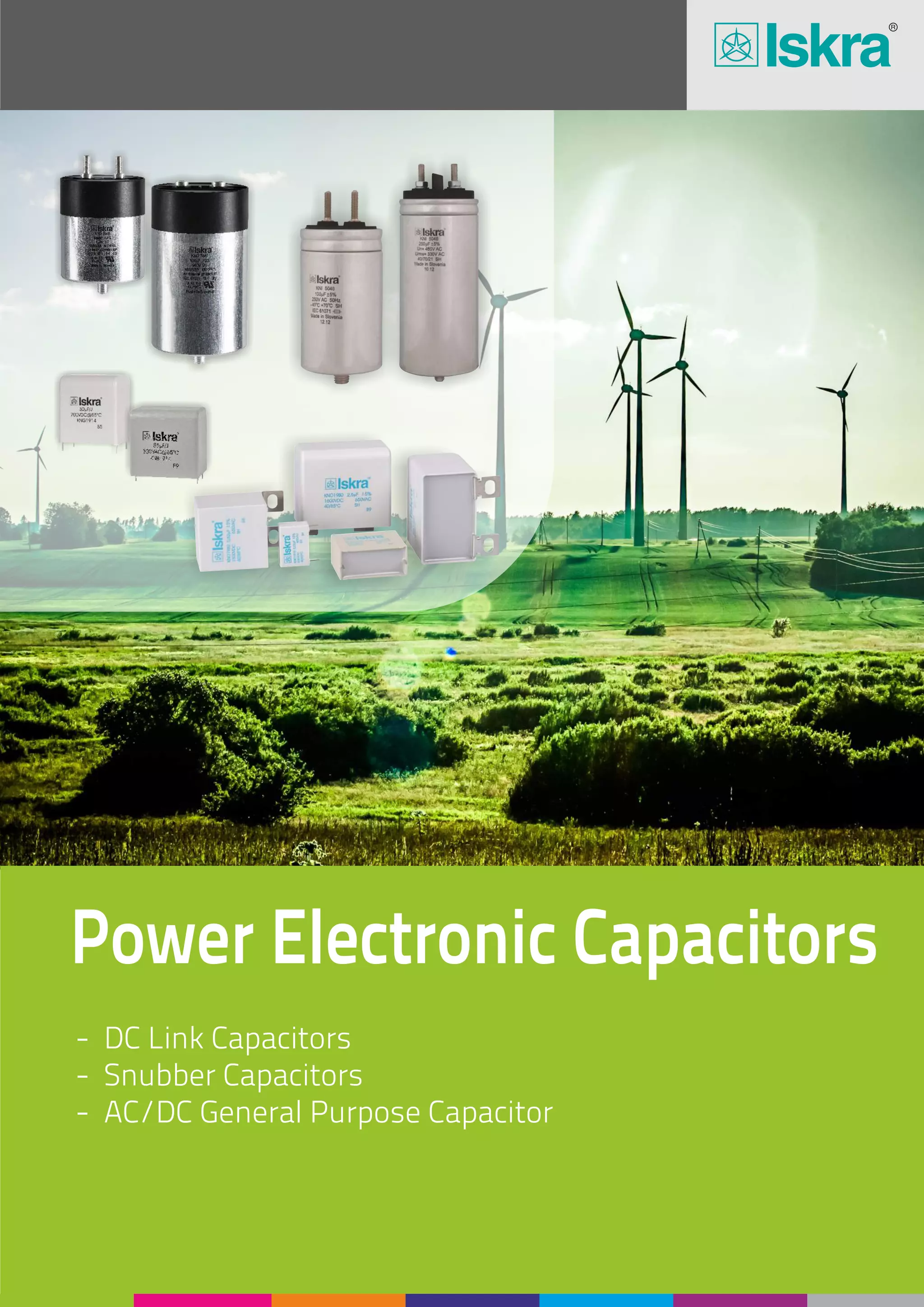


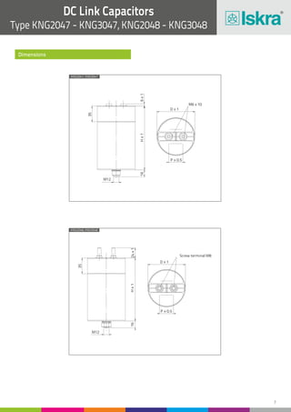
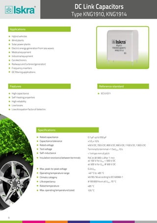
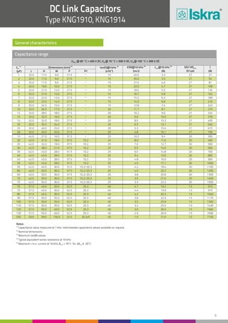
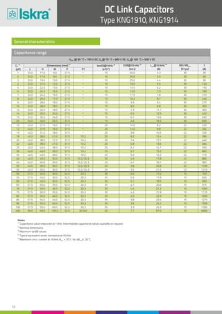

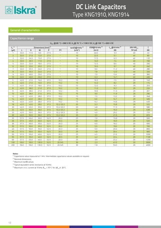
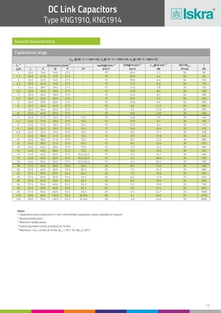
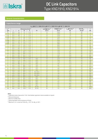
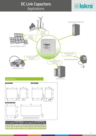
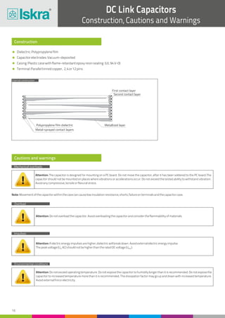
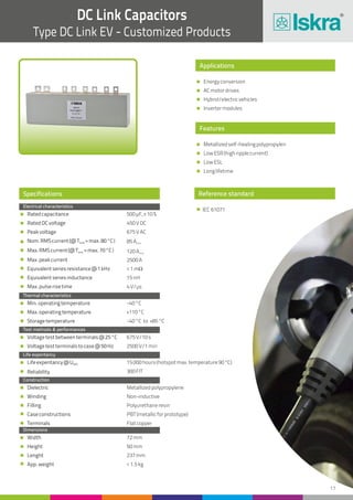
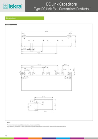
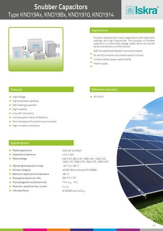
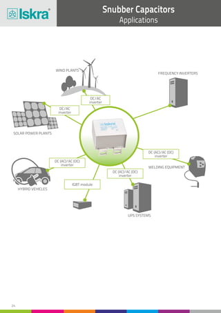
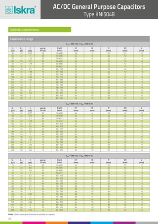
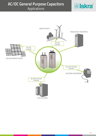


The document discusses various types of power electronic capacitors produced by Iskra, including DC link capacitors and snubber capacitors used in electric circuits such as inverters and power supplies. It outlines their applications, specifications, and key performance characteristics, emphasizing their suitability for a range of systems like wind and solar power, electric vehicles, and industrial equipment. Additionally, the document provides detailed technical data and standards for different capacitor models.


![Getting Started with Apache Spark: Big Data Made Simple [Free Meetup]](https://cdn.slidesharecdn.com/ss_thumbnails/apachesparkgettingstarted-260203175547-8361bcc3-thumbnail.jpg?width=640&height=640&fit=bounds)


