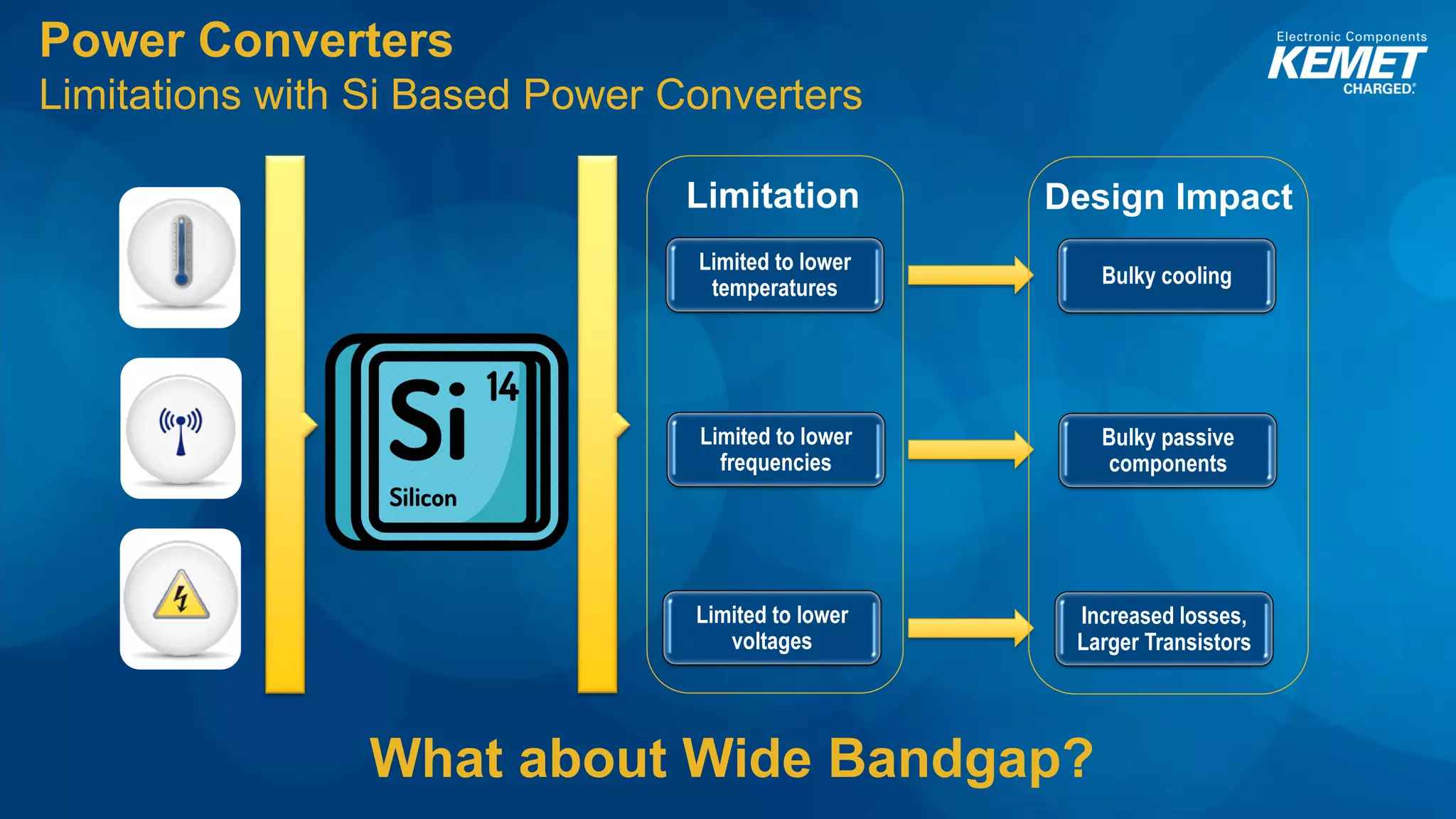
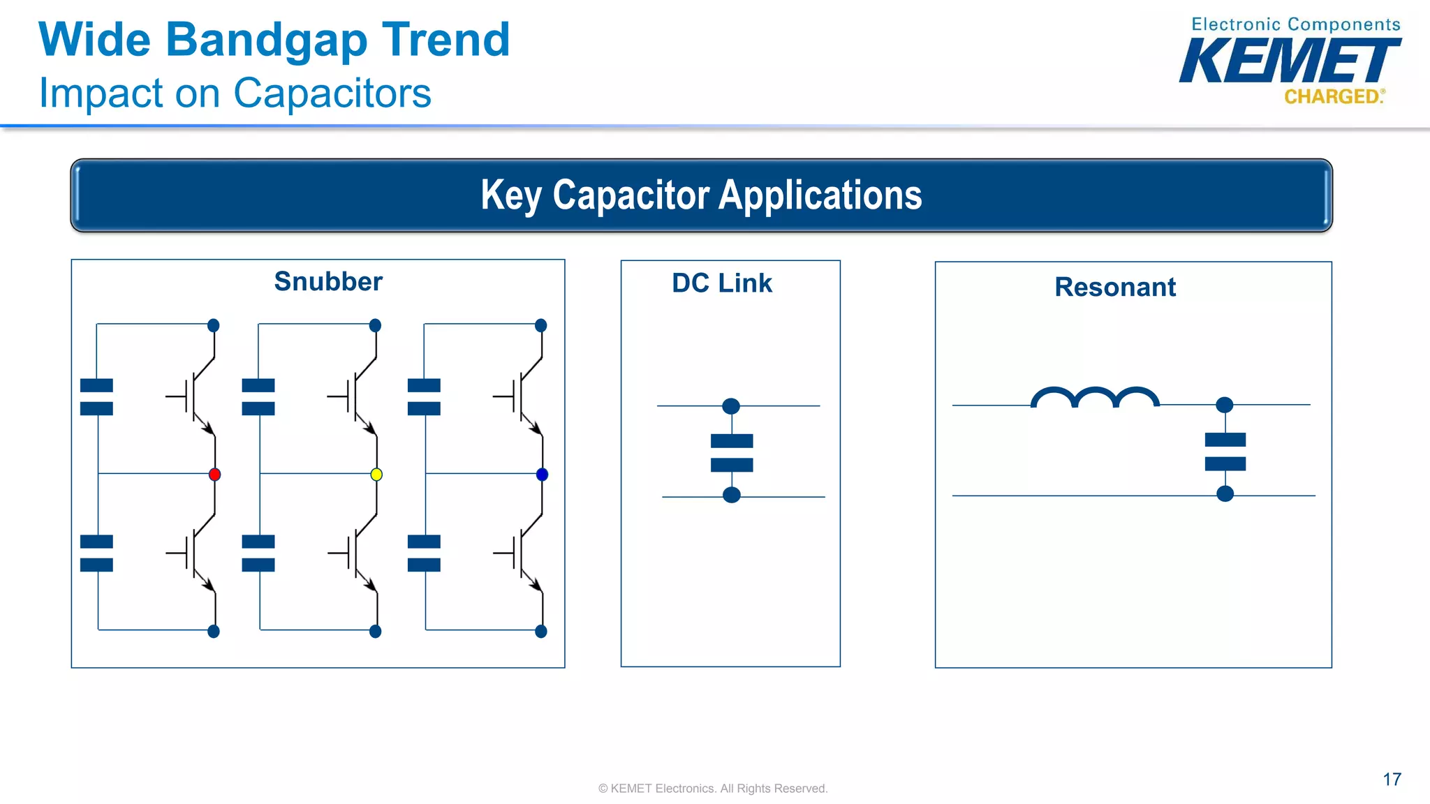
What’s a Ceramic KC-LINK Capacitor
Doing in My Power Converter?
Webinar
October 22nd, 2018
Outline
1. Power Conversion
2. Wide Bandgap Semiconductor Technology
3. KC-LINK: Overview, Performance,
Competition, Ordering
4. Future Developments
5. Summary
Power Conversion
Phone charger
Electric vehicles
Power conversion
involves converting
one type of electrical
power to another.
Solar panels
4© KEMET Electronics. All Rights Reserved.
Power Converters
Basic topologies, AC-AC
AC
DC
DC
AC
Input Power Output Power
AC-AC
1
5© KEMET Electronics. All Rights Reserved.
Power Converters
Basic topologies, DC-AC
Input Power Output Power
DC-AC
2
AC
DC
6© KEMET Electronics. All Rights Reserved.
Power Converters
Basic topologies, AC-DC
AC-DC
3
AC
DC
DC
DC
Input Power Output Power
Power Converters
Transistors Make it Possible!
Transistors (Electronic Switch)
Traditionally Silicon Based (Si)
Power Converters
3 Design Goals
WeightSize Efficiency
Input Output
1 2 3
Power Converters
Efficiency Explained
Input Power Output Power
100kW 100kW
Input Power Output Power
100kW 90kW
Actual Power Converter
Ideal Power Converter
Efficiency=100%
Efficiency=90%
𝐸𝑓𝑓𝑖𝑐𝑖𝑒𝑛𝑐𝑦 =
𝑂𝑢𝑡𝑝𝑢𝑡 𝑃𝑜𝑤𝑒𝑟
𝐼𝑛𝑝𝑢𝑡 𝑃𝑜𝑤𝑒𝑟
x 100%
Power Converters
Solar Energy Electric Vehicles Data Centers
90% to 90.5% (+0.5%) = BIG SAVINGS
Every 0.5% Matters!
12© KEMET Electronics. All Rights Reserved.
Power Converters
Improving Size, Weight, and Efficiency
Increase Allowable
Transistor
Temperature
Increase
Frequency
Increase
Voltage
No bulky
cooling Smaller passive
components
Lower losses
Lower
losses
Reduced
Weight
Smaller
Size
Improved
Efficiency
1 2 3
Power Converters
Limitations with Si Based Power Converters
Limited to lower
temperatures
Bulky cooling
Limited to lower
frequencies
Bulky passive
components
Limited to lower
voltages
Increased losses,
Larger Transistors
Limitation Design Impact
What about Wide Bandgap?
Wide Bandgap (WBG) Semiconductors
Density of StatesElectronEnergy
Non-Conductive band
Semiconductor Material
Bandgap
Energy (eV)
Germanium (Ge) 0.7
Silicon (Si) 1.1
Silicon Carbide (SiC) 3.3
Gallium Nitride (GaN) 3.4
WBG
ConductorsInsulators Semiconductors
10-20 10810410010-410-810-1210-16
Conductivity (S/cm)
Frequency (Hz)
Power(W)
100 1k 10k 100k 1M 10M 100M 1G 10G 100G
10
100
1k
10k
100k
1M
10M
100M The BIG 3 for WBG
-Higher Voltages
-Higher Frequencies
-Higher Temperatures
Si
SiC
Si
Power Converter
GaN
Wide Bandgap (WBG) Semiconductors
Wide Bandgap Based Power Converters
Smaller (Higher Power
Densities)
Less Cooling
More EfficientPower
Conversion
Si Based
WBG Based on GaN
or SiC
DC to DC 85% 95%
AC to DC 85% 90%
DC to AC 96% 99%
Source: Mouser Electronics, L. Culberson, 2016
Typical Si
50kW inverter
WBG SiC
50kW inverter
17© KEMET Electronics. All Rights Reserved.
Wide Bandgap Trend
Impact on Capacitors
Snubber DC Link Resonant
Key Capacitor Applications
18© KEMET Electronics. All Rights Reserved.
0.00
0.01
0.10
1.00
10.00
10 100 1,000 10,000
Capacitance(uF)
Frequency kHz
DC-LINK Capacitance vs Switching Frequency and Voltage
10kW Power Converter
400V 650V 1000V
Wide Bandgap Trend
Impact on Capacitors
* Source: Prof. R. Kennel, Technical University Munich, Germany
Higher Voltage = Lower Capacitance
With WBG
adoption,
Ceramic Caps
play a key role
supporting
semiconductors for
improving
efficiency in
power conversion.
Wide Bandgap Trend
Impact on Capacitors
Capacitor RequirementThe BIG 3 for WBG
Smaller, low ESR, low ESL low loss
capacitors with high current handling
capability
Higher Switching Frequencies
20kHz → 100kHz → 100’s MHz
Higher Operation Voltages
400V → 900V →1200V→1700V
Reliable performance at higher voltages
High Junction Temperatures
105oC → 125oC → 200oC+
Reliable performance at elevated
temperatures ≥ 125oC with robust mechanical
performance
Packaging close to the hot semiconductor to:
• Lower ESL
• Minimize cooling costs
KC-LINK
• AEC-Q200 automotive qualified
• Very high ripple current capability
• Extremely low ESR
• Extremely low ESL
• Operating temperature range of −55°C to +150°C
• High frequency operation (>10 MHz)
• No capacitance shift with voltage
• No piezoelectric noise
• High thermal stability
• RoHS Pb-free
• Wide bandgap (WBG), silicon carbide (SiC) and gallium
nitride (GaN) systems
• EV/HEV (drive systems, charging)
• Wireless charging
• Photovoltaic systems
• Power converters
• Inverters
• LLC resonant converters
• DC-Link
• Snubber
Features and Benefits Applications
Competition
KEMET KC-LINK TDK CeraLink
Tale of the Tape
KEMET KC-LINK TDK CeraLink
220nF Capacitance ~600nF
CaZrO3 Dielectric Cu PLZT
Yes Pb-Free No
Yes RoHS
Yes, only by
exemption
150oC Operating Temp 150oC
< 0.10% DF (%) @1kHz < 2.0%
<4mΩ
Typical ESR
@100kHz
~65mΩ
17.1 Arms
Ripple Current
@100kHz, 105oC
9.7 Arms
~1nH Typical ESL ~2.5nH
No, not required Lead Frame Yes, required
>250
Average MOR
(MPa)
<125
26© KEMET Electronics. All Rights Reserved.
KC-LINK vs TDK CeraLink
Capacitance Stability
* Source: TDK CeraLink Datasheet
KEMET KC-LINK TDK CeraLink
KEMET’S KC-LINK remains ultra stable
over voltage and temperature!
27© KEMET Electronics. All Rights Reserved.
0
5
10
15
20
25
30
35
0 5 10 15 20
TemperatureRise(°C)
Ripple Current (ARMS)
Frequency (100kHz)
KC-Link
CeraLink
KC-LINK vs TDK CeraLink
Impedance, ESR, and Ripple Current
1.0E-04
1.0E-03
1.0E-02
1.0E-01
1.0E+00
1.0E+01
1.0E+02
10 100 1,000 10,000 100,000
Impedance&ESR(Ω)
Frequency (kHz)
KC-Link Impedance
KC-Link ESR
CeraLink Impedance
CeraLink ESR
KEMET’S KC-LINK ESR is lower, providing excellent ripple current handling.
KC-LINK’s temperature rise remains very low (20°C) at higher ripple currents.
28© KEMET Electronics. All Rights Reserved.
KC-LINK vs TDK CeraLink
Accelerated Life Testing
0%
10%
20%
30%
40%
50%
60%
70%
80%
90%
CummulativeFailures(%)
Time (hours)
KC-LINK
CeraLink
0 250 500 750 1000
Accelerated Life Testing @600Vdc 200oC
KEMET’S KC-LINK had no
failures during the entire
test!
KC-LINK: How to Order
Commercial & Auto grade available
KC-LINK Under Development Offering
Available to order now:
CKC33C224KCGACTU
Rest of the waterfall:
UD
KC-LINK with KONNEKT Technology
Under Development
Voltage KC-LINK 150°C
Case size 3640
Chips 4
500V 0.88uF
650V 0.60uF
1000V 220nF
1200V 190nF
1700V 88nF
Uses innovative
Transient Liquid Phase
Sintering –TLPS–
technology to bond
component
terminations together
Cross section of KONNEKT ceramic capacitor
Standard
mounting
Low-loss
mounting
Summary
• Wide Band Gap – Remember the BIG 3!
• Higher Voltages
• Higher Frequencies
• Higher Temperatures
• KEMET KC-LINK
• Extremely low equivalent series resistance (ESR)
• Extremely low equivalent series inductance (ESL)
• Very high ripple current capability
• Ideal solution for snubber, DC-LINK and resonant applications
Snubber DC Link Resonant
Thank you!
Ana Ogui Magaña
Technical Product Specialist - Ceramic Business Unit
KEMET Electronics
Office Phone: +1-864-963-4580
anamagana@kemet.com

Kemet KC-LINK Webinar

  • 1.
    What’s a CeramicKC-LINK Capacitor Doing in My Power Converter? Webinar October 22nd, 2018
  • 2.
    Outline 1. Power Conversion 2.Wide Bandgap Semiconductor Technology 3. KC-LINK: Overview, Performance, Competition, Ordering 4. Future Developments 5. Summary
  • 3.
    Power Conversion Phone charger Electricvehicles Power conversion involves converting one type of electrical power to another. Solar panels
  • 4.
    4© KEMET Electronics.All Rights Reserved. Power Converters Basic topologies, AC-AC AC DC DC AC Input Power Output Power AC-AC 1
  • 5.
    5© KEMET Electronics.All Rights Reserved. Power Converters Basic topologies, DC-AC Input Power Output Power DC-AC 2 AC DC
  • 6.
    6© KEMET Electronics.All Rights Reserved. Power Converters Basic topologies, AC-DC AC-DC 3 AC DC DC DC Input Power Output Power
  • 7.
    Power Converters Transistors Makeit Possible! Transistors (Electronic Switch) Traditionally Silicon Based (Si)
  • 8.
    Power Converters 3 DesignGoals WeightSize Efficiency Input Output 1 2 3
  • 9.
    Power Converters Efficiency Explained InputPower Output Power 100kW 100kW Input Power Output Power 100kW 90kW Actual Power Converter Ideal Power Converter Efficiency=100% Efficiency=90% 𝐸𝑓𝑓𝑖𝑐𝑖𝑒𝑛𝑐𝑦 = 𝑂𝑢𝑡𝑝𝑢𝑡 𝑃𝑜𝑤𝑒𝑟 𝐼𝑛𝑝𝑢𝑡 𝑃𝑜𝑤𝑒𝑟 x 100%
  • 10.
    Power Converters Solar EnergyElectric Vehicles Data Centers 90% to 90.5% (+0.5%) = BIG SAVINGS Every 0.5% Matters!
  • 11.
    12© KEMET Electronics.All Rights Reserved. Power Converters Improving Size, Weight, and Efficiency Increase Allowable Transistor Temperature Increase Frequency Increase Voltage No bulky cooling Smaller passive components Lower losses Lower losses Reduced Weight Smaller Size Improved Efficiency 1 2 3
  • 12.
    Power Converters Limitations withSi Based Power Converters Limited to lower temperatures Bulky cooling Limited to lower frequencies Bulky passive components Limited to lower voltages Increased losses, Larger Transistors Limitation Design Impact What about Wide Bandgap?
  • 13.
    Wide Bandgap (WBG)Semiconductors Density of StatesElectronEnergy Non-Conductive band Semiconductor Material Bandgap Energy (eV) Germanium (Ge) 0.7 Silicon (Si) 1.1 Silicon Carbide (SiC) 3.3 Gallium Nitride (GaN) 3.4 WBG ConductorsInsulators Semiconductors 10-20 10810410010-410-810-1210-16 Conductivity (S/cm)
  • 14.
    Frequency (Hz) Power(W) 100 1k10k 100k 1M 10M 100M 1G 10G 100G 10 100 1k 10k 100k 1M 10M 100M The BIG 3 for WBG -Higher Voltages -Higher Frequencies -Higher Temperatures Si SiC Si Power Converter GaN Wide Bandgap (WBG) Semiconductors
  • 15.
    Wide Bandgap BasedPower Converters Smaller (Higher Power Densities) Less Cooling More EfficientPower Conversion Si Based WBG Based on GaN or SiC DC to DC 85% 95% AC to DC 85% 90% DC to AC 96% 99% Source: Mouser Electronics, L. Culberson, 2016 Typical Si 50kW inverter WBG SiC 50kW inverter
  • 16.
    17© KEMET Electronics.All Rights Reserved. Wide Bandgap Trend Impact on Capacitors Snubber DC Link Resonant Key Capacitor Applications
  • 17.
    18© KEMET Electronics.All Rights Reserved. 0.00 0.01 0.10 1.00 10.00 10 100 1,000 10,000 Capacitance(uF) Frequency kHz DC-LINK Capacitance vs Switching Frequency and Voltage 10kW Power Converter 400V 650V 1000V Wide Bandgap Trend Impact on Capacitors * Source: Prof. R. Kennel, Technical University Munich, Germany Higher Voltage = Lower Capacitance With WBG adoption, Ceramic Caps play a key role supporting semiconductors for improving efficiency in power conversion.
  • 18.
    Wide Bandgap Trend Impacton Capacitors Capacitor RequirementThe BIG 3 for WBG Smaller, low ESR, low ESL low loss capacitors with high current handling capability Higher Switching Frequencies 20kHz → 100kHz → 100’s MHz Higher Operation Voltages 400V → 900V →1200V→1700V Reliable performance at higher voltages High Junction Temperatures 105oC → 125oC → 200oC+ Reliable performance at elevated temperatures ≥ 125oC with robust mechanical performance Packaging close to the hot semiconductor to: • Lower ESL • Minimize cooling costs
  • 19.
    KC-LINK • AEC-Q200 automotivequalified • Very high ripple current capability • Extremely low ESR • Extremely low ESL • Operating temperature range of −55°C to +150°C • High frequency operation (>10 MHz) • No capacitance shift with voltage • No piezoelectric noise • High thermal stability • RoHS Pb-free • Wide bandgap (WBG), silicon carbide (SiC) and gallium nitride (GaN) systems • EV/HEV (drive systems, charging) • Wireless charging • Photovoltaic systems • Power converters • Inverters • LLC resonant converters • DC-Link • Snubber Features and Benefits Applications
  • 20.
  • 21.
    Tale of theTape KEMET KC-LINK TDK CeraLink 220nF Capacitance ~600nF CaZrO3 Dielectric Cu PLZT Yes Pb-Free No Yes RoHS Yes, only by exemption 150oC Operating Temp 150oC < 0.10% DF (%) @1kHz < 2.0% <4mΩ Typical ESR @100kHz ~65mΩ 17.1 Arms Ripple Current @100kHz, 105oC 9.7 Arms ~1nH Typical ESL ~2.5nH No, not required Lead Frame Yes, required >250 Average MOR (MPa) <125
  • 22.
    26© KEMET Electronics.All Rights Reserved. KC-LINK vs TDK CeraLink Capacitance Stability * Source: TDK CeraLink Datasheet KEMET KC-LINK TDK CeraLink KEMET’S KC-LINK remains ultra stable over voltage and temperature!
  • 23.
    27© KEMET Electronics.All Rights Reserved. 0 5 10 15 20 25 30 35 0 5 10 15 20 TemperatureRise(°C) Ripple Current (ARMS) Frequency (100kHz) KC-Link CeraLink KC-LINK vs TDK CeraLink Impedance, ESR, and Ripple Current 1.0E-04 1.0E-03 1.0E-02 1.0E-01 1.0E+00 1.0E+01 1.0E+02 10 100 1,000 10,000 100,000 Impedance&ESR(Ω) Frequency (kHz) KC-Link Impedance KC-Link ESR CeraLink Impedance CeraLink ESR KEMET’S KC-LINK ESR is lower, providing excellent ripple current handling. KC-LINK’s temperature rise remains very low (20°C) at higher ripple currents.
  • 24.
    28© KEMET Electronics.All Rights Reserved. KC-LINK vs TDK CeraLink Accelerated Life Testing 0% 10% 20% 30% 40% 50% 60% 70% 80% 90% CummulativeFailures(%) Time (hours) KC-LINK CeraLink 0 250 500 750 1000 Accelerated Life Testing @600Vdc 200oC KEMET’S KC-LINK had no failures during the entire test!
  • 25.
    KC-LINK: How toOrder Commercial & Auto grade available
  • 26.
    KC-LINK Under DevelopmentOffering Available to order now: CKC33C224KCGACTU Rest of the waterfall: UD
  • 27.
    KC-LINK with KONNEKTTechnology Under Development Voltage KC-LINK 150°C Case size 3640 Chips 4 500V 0.88uF 650V 0.60uF 1000V 220nF 1200V 190nF 1700V 88nF Uses innovative Transient Liquid Phase Sintering –TLPS– technology to bond component terminations together Cross section of KONNEKT ceramic capacitor Standard mounting Low-loss mounting
  • 28.
    Summary • Wide BandGap – Remember the BIG 3! • Higher Voltages • Higher Frequencies • Higher Temperatures • KEMET KC-LINK • Extremely low equivalent series resistance (ESR) • Extremely low equivalent series inductance (ESL) • Very high ripple current capability • Ideal solution for snubber, DC-LINK and resonant applications Snubber DC Link Resonant
  • 29.
    Thank you! Ana OguiMagaña Technical Product Specialist - Ceramic Business Unit KEMET Electronics Office Phone: +1-864-963-4580 anamagana@kemet.com