Epcos 5
•
0 likes•2,070 views

catalogo de seleccion de condensadores electricos para poder bajar el consumo de arranque de motores electricos al momento de encerder el equipo.

Recommended
More Related Content
What's hot
What's hot (20)
Similar to Epcos 5
Similar to Epcos 5 (20)
Recently uploaded
Recently uploaded (20)
Epcos 5
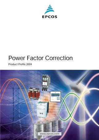
- 1. Power Factor Correction Product Profile 2004 www.epcos.com
- 2. L1 L2 L3 U I
- 3. Preview General Awareness of the necessity of power quality is increasing, and power factor correction (PFC) will be implemented on a growing scale in future. Enhancing power quality – improvement of power factor – saves costs and ensures a fast return on investment. In power distribution, in low- and medium-voltage networks, PFC focuses on the power flow (cos ϕ) and the optimization of voltage stability by generating reactive power – to improve voltage quality and reliability at distribution level. How reactive power is generated Every electric load that works with magnetic fields (motors, chokes, transformers, inductive heating, arc-welding generators) produces a varying degree of electrical lag, which is called inductance. This lag of inductive loads maintains the current sense (e.g. positive) for a time even though the negative-going voltage tries to reverse it. This phase shift between current and voltage is maintained, current and voltage having opposite signs. During this time, negative power or energy is produced and fed back into the network. When cur-rent and voltage have the same sign again, the same amount of energy is again needed to build up the magnetic fields in inductive loads. This magnetic reversal energy is called reactive power. In AC networks (50/60 Hz) such a process is repeated 50 or 60 times a second. So an obvious solution is to briefly store the magnetic reversal energy in capacitors and relieve the network (supply line) of this reactive energy. For this reason, automatic reactive power compensation systems (detuned/conventional) are installed for larger loads like industrial machinery. Such systems consist of a group of capacitor units that can be cut in and cut out and which are driven and switched by a power factor controller. Power factor Low power factor (cos ϕ) Low cos ϕ results in higher energy consumption and costs, less power distributed via the network, power loss in the network, higher transformer losses, increased voltage drop in power distribution networks. Power factor improvement Power factor improvement can be achieved by compensation of reactive power with capacitors, active compensation – using semiconductors, overexcited synchronous machine (motor/generator). Types of PFC (detuned or conventional) individual or fixed compensation (each reactive power producer is individually compensated), group compensation (reactive power producers connected as a group and compensated as a whole), central or automatic compensa-tion (by a PFC system at a central point), mixed compensation. EPCOS AG 3
- 4. Contents PFC capacitor series overview 6 Five PFC capacitor series cover all requirements for power factor correction and detuned filters Information about PFC capacitors 8 Design of capacitors – MKK/MKP technology – Self-healing – Vacuum impregnation – Overpressure disconnector Cautions – Temperature class of capacitors to standard IEC 831-1 – Enclosure of capacitors (IPxx) – Current rating / Maximum admissible overcurrent – Maximum admissible overvoltage – Mean life expectancy – Fuse protection – Switching of capacitors – Discharging – Capacitors in networks with harmonics – Installation – Mechanical damage – Vibration resistance – Connection – Grounding – Storage and operating condition 4 EPCOS AG
- 5. PFC capacitors PhaseCap Premium capacitors (230 … 525 V, 5.0 … 33.8 kvar/premium) ............................ 16 PhaseCap HD capacitors (400 … 525 V, 40.0 … 60.0 kvar/heavy duty) ...................... 23 WindCap capacitors (690 … 800 V, 5.0 … 36.0 kvar/wind turbine) ...................... 27 PhiCap capacitors (230 … 525 V, 0.5 … 30.0 kvar/economical) ........................ 32 MKV Cap capacitors (400 … 690 V, 5.0 … 18.0 kvar/ up to + 70 °C ambient temperature) .................................... 41 PFC controllers BR604 and BR6000 series .................................................. 44 Capacitor contactors 50 Reactors Antiresonance harmonic filter reactor .................................. 54 Discharge reactor ................................................................ 60 Dynamic power factor correction Thyristor module TSM-LC.................................................... 62 Fundamentals of power factor correction General information ............................................................ 66 Formulas ............................................................................ 68 Cautions, installation and maintenance ................................ 71 Selection tables .................................................................. 75 Detuned filtering .................................................................. 77 Table of required kvar .......................................................... 79 Component selection table .................................................. 80 Further publications ............................................................ 87 1 2 3 4 5 6 EPCOS AG 5
- 6. PFC Capacitor Series Overview Five PFC capacitor series for power factor correction and detuned filter Parameter Symbol / Unit PhaseCap™ Premium PhaseCap™ HD Power QR [kvar] 5.0 ... 33.8 40.0 ... 60.0 Rated voltage VR [VAC] 230 ... 525 400 ... 525 Inrush current IS [A] up to 200 * IR up to 200 * IR Temperature class –25/D –25/D Max. temp. 55 °C Max. temp. 55 °C Max. mean 24 h = 45 °C Max. mean 24 h = 45 °C Max. mean 1 year = 35 °C Max. mean 1 year = 35 °C Losses: – Dielectric QL [W/kvar] 0.2 0.2 – Total QL [W/kvar] 0.45 0.35 Max. humidity Hrel 95% 95% Safety – triple (self-healing, overpressure triple (self-healing, overpressure disconnector, dry technology) disconnector, dry technology) Impregnation – inert gas inert gas Mean life expectancy DB(co) up to 115 000 h up to 130 000 h Connection – SIGUT™, block-type, SIGUT™, block-type, safety terminal safety terminal Cooling – natural natural Case/shape – aluminum/cylindrical aluminum/cylindrical Enclosure IPxx IP20, optionally IP54 IP20 Standard IEC 831-1+2, UL 810 5th edition, IEC 831-1+2, UL 810 5th edition cULfile # E238746 Application PFC and detuned systems PFC and detuned systems 6 EPCOS AG
- 7. WindCap™ PhiCap MKV Cap 5.0 ... 36.0 0.5 ... 30.0 5.0 … 18.0 690 ... 800 230 ... 525 400 … 690 up to 300 * IR up to 200 * IR up to 300 * IR –25/D –25/D –25 ... +70 °C Max. temp. 55 °C Max. temp. 55 °C Max. temp. 70 °C Max. mean 24 h = 45 °C Max. mean 24 h = 45 °C Max. mean 24 h = 55 °C Max. mean 1 year = 35 °C Max. mean 1 year = 35 °C Max. mean 1 year = 45 °C 0.2 0.2 0.2 0.4 0.45 0.5 95% 95% 95% triple (self-healing, overpressure dual (self-healing, overpressure disconnector) dual (self-healing, overpressure disconnector, dry technology) disconnector) inert gas soft resin oil up to 130 000 h up to 100 000 h up to 150 000 h SIGUT™, block-type, B32344 series: screw terminal safety terminal SIGUT™, block-type, safety terminal B32340/B32343 series: fast-on terminals natural natural natural aluminum/cylindrical aluminum/cylindrical aluminum/cylindrical IP20, optionally IP54 IP00, IP20, optionally IP54 IP00 IEC 831-1+2, UL 810 5th edition, IEC 831-1+2, UL 810 5th edition IEC 831-1+2, cUL file # E96954 cUL file # E238746 PFC, detuned systems and wind turbines PFC and detuned systems PFC and harmonic filtering EPCOS AG 7
- 8. Information about PFC Capacitors Wavy cut design Capacitor windings Film and film-free margin Metalization Metalization Metal spraying layer (Zn) Design of capacitors MKK/MKP technology The broad field of application for capacitors combined with physical and economic considerations creates the need for different dielectric technologies. When it comes to low-voltage power factor correction, MKK/MKP technology (metalized plastic film/polypropylene) has turned out as currently the most suitable and most economic technology. The thickness of the dielectric differs as Section A Section A Heavy edge EPCOS wavy cut Metalization Metalization Metalization Film and film-free margin Flame-sprayed contact area (Zn) Large effective contact area a function of voltage rating. The metalization (with zinc and alu-minum as its major constituents) and edge enhancement with extra junctions or cross-profile metalization play a significant role in achieving high current handling and stable capacitance. Heavy-edge and special film cutting technique (optimized combination Solid contact zone Heavy edge Without EPCOS wavy cut Cracks possible Flame-sprayed area of wavy and smooth cuts) pro-duces a maximum effective surface for the metal spraying or contacting process (winding design). This results in high surge current with-stand capability. The buckling effect on the film edge of the winding – the cause of contact edge problems – is eliminated in this way. 8 EPCOS AG
- 9. Self-healing 30 μm 10 μm Self-healing An electric breakdown is possible as the result of thermal or electric overload or at the end of useful life. This results in a small arc that evaporates the metalization in the region of the breakdown in a matter of microseconds. The gas pressure caused at this spot by the high temperature blows the now vaporous metalization out of the breakdown region. 4 2 6 2 4 5 1 9 7 9 3 1 10 r 8 10 1 5 4 2 1 Dielectric 2 Metalized electrodes 3 Material displacing shock wave 4 Air gap with metal vapor 5,6 Plasma zone 7 Boundary layer between gas phase dielectric and plasma 8 Breakdown channel 9 Gas phase dielectric 10 Zone of displaced metalization and dielectric (isolating region) x 2 4 6 7 9 3 10 1 10 This means that a non-conducting isolation region free of metalization is formed here. During and after the breakdown the capacitor is fully functional. The reduction in capacitance caused by self-healing is less than 100 pF, i.e. of an order that can only be verified by a precision measuring instrument. Vacuum impregnation The active winding elements are heated and then dried for a defined period. Impregnation (e.g. by gas) is performed under vacuum. In this way air and moisture are extracted from the inner capacitor, and oxidation of the electrodes as well as partial discharges are avoided. Afterwards capacitors are hermetically sealed in cases (e.g. aluminum). The elaborate process ensures excellent capaci-tance stability and long service life. EPCOS AG 9
- 10. Overpressure disconnector Expansion bead Expansion top Solid connected Overpressure disconnector Electrical components do not have unlimited life expectancy; this applies to self-healing capacitors too. As polypropylene-type capaci-tors seldom produce a pronounced short circuit, HCR fuses or circuit breakers alone do not offer sufficient protection. All capacitors featured in this cata-log are consequently fitted with a disconnector that responds only to overpressure. If numerous electric Overpressure disconnector activated Pressure breakdowns occur over time or as the result of thermal or electric overload (within IEC 831 specifica-tion), the formation of gas pro-duces a rise in pressure inside the capacitor case. This causes a change in length because of curva-ture of the lid or stretching of the expansion bead. Expansion beyond a certain degree will sepa-rate the internal wires and discon-nect the capacitor from the line. FAILURE TO FOLLOW CAUTIONS (P. 10–13) MAY RESULT, WORST CASE, IN PREMATURE FAILURES, BURSTING AND FIRE. Caution: To ensure full functionality of an overpressure disconnector, the following is required: 1. The elastic elements must not be hindered, i.e. – connecting lines must be flexible leads (cables), – there must be sufficient space for expansion above the connections (stated for the different models), – folding beads must not be retained by clamps. 2. Maximum allowed fault current of 10 000 A in accordance with UL 810-standard must not be exceeded. 3. Stress parameters of the capacitor must be within IEC 831 specification. 10 EPCOS AG
- 11. Cautions Temperature class of capacitors (according IEC 831-1) Temperature class Temperature of capacitor surrounding air Maximum Maximum mean for 24 h Maximum mean for 1 year B 45 °C 35 °C 25 °C C 50 °C 40 °C 30 °C D 55 °C 45 °C 35 °C Enclosure of capacitors (IPxx) Enclosure First digit Second digit IP00 No protection against finger touch and ingress of solid foreign bodies No protection against ingress of water IP20 Protection against finger touch and solid foreign bodies ≥ 12.5 mm diameter No protection against ingress of water IP41 Protection against tool touch and solid foreign bodies ≥ 1 mm diameter Drip-water protection IP54 Protection against tool touch and solid foreign bodies ≥ 1 mm diameter, Splash water protection protection against dust deposit Maximum admissible overvoltage Frequency Max. voltage Max. duration Remarks 50/60 Hz (Vrms) Line frequency 1.00 * VR Continuous duty Highest mean during entire operating time of capacitor; exceptions (see below) are admissible for times of 24 h Line frequency 1.10 * VR 8 h daily Line voltage fluctuations Line frequency 1.15 * VR 30 min daily Line voltage fluctuations Line frequency 1.20 * VR 5 min daily Line voltage fluctuations Line frequency 1.30 * VR 1 min daily Line voltage fluctuations Line frequency Such that current does not exceed maximum admissible figure (Imax. = 1.3 * IR) with harmonics Temperature class of capaci-tors to standard IEC 831-1 Capacitors are divided into tem-perature classes. Each class is represented by a number followed by a letter, e.g. –25/D. The number is the lowest ambient temperature at which a capacitor may operate. The upper limit temperature is indicated by the letter (see table above). The useful life of a capacitor depends very much on tempera-ture. Proper cooling of a capacitor must ensure that the maximum temperature is not exceeded, other-wise useful life is degraded. When configuring a circuit, one should make sure that capacitors are not subjected to heat from adjacent components (reactors, bus bars, etc). Forced cooling is preferable for compact designs. And it is highly inadvisable to arrange capacitors directly above reactors. Exeeding specified temperature limits may set in worst case the safety device out of operation. Enclosure of capacitors (IPxx) For different models there are different types of enclosure. The type of enclosure is indicated by a designation consisting of the two letters IP followed by two digits. Current rating/maximum admissible overcurrent The rated current (IR) is the current resulting for rated voltage (VR) and frequency (in Hz), excluding transients. Maximum permitted RMS current for each particular capacitor is specified in the data sheet. Continuously exceeding of the nomi-nal current will lead to increased self-heating of the capacitor and reduce life time. The maximum admissible overcurrent (Imax) of 1.3*IR to IEC standard 831 is maintained by all capacitors in this catalog. The figures for overcurrent allow for the combined effects of harmonics, over-voltage and capacitance tolerance. Maximum admissible overvoltage Capacitors from EPCOS are suit-able for operation on overvoltages quoted by IEC 831 (see table). Overvoltages higher than 1.15 *VR reduce life time of the capacitor and must not occur more than 200 times during life time of capacitor. Overvoltages above 1.3 *VR must not occur at all, appropriate over-voltage protection (e.g. against lightning strikes) must be ensured. Mean life expectancy The mean life expectancy of power capacitors is mainly governed by the following factors: – duration of overload, – ambient temperature and the resulting case temperature, – maximum rms current and the resulting case temperature, – voltage height and duration. The calculated life expectancy of the various series is stated for nominal operating conditions. If components are stressed less than the IEC 831 factors, longer useful life can be expected, and a correspondingly shorter one or increased failure rate if nominal parameters are exceeded. EPCOS AG 11
- 12. Cautions Fuse protection Power capacitors have to be pro-tected against short circuits by fuses or thermal magnetic overcur-rent relays. Slow-blow, low-voltage high-breaking-capacity fuses (HRC) are preferable. The fuse rating should be 1.6 to 1.8 times the rated current of the capacitor. Magnetic short circuit relays should be set to between 9 and 12 times rated cur-rent to prevent them responding to high inrush currents. Maximum allowed fault current of 10 000 A in accordance with UL 810 standard must be ensured by the application design. HRC fuses must not be used for switching. Resulting electric arcing can cause death! It may also cause capacitor failures, and result, worst case, in capacitor bursting and fire. Switching of capacitors When a capacitor is switched to an AC system, the result is a resonant circuit damped to a greater or less-er degree. In addition to the rated current, the capacitor accepts a transient current that is a multiple of (up to 200 times) its rated cur-rent. Fast switching, low-bounce contactors should be used, and have the switching capacity for capacitive currents stated by the producer. Special capacitor con-tactors with leading contacts that feature precharging resistors to damp inrush currents are recom-mended. As per IEC 831 standard, a maximum of 5 000 switching operations per year is acceptable. Before considering a higher number of switching operations, please contact EPCOS. Discharging Capacitors must be discharged to a maximum of 10 % of rated volt-age before they are switched in again. This prevents an electric impulse discharge in the applica-tion, influences the capacitor‘s useful life in PFC systems, and protects against electric shock. The capacitor must be discharged to 75 V or less within 3 min. There must not be any switch, fuse or any other disconnecting device in the circuit between the power capacitor and the discharging device. EPCOS supplies capacitor discharge resistors to all series, alternatively discharge reactors are available. Caution: Discharge and short circuit capacitor before handling! Capacitors in networks with harmonics Harmonics are produced in the operation of electric loads with a nonlinear voltage/current charac-teristic (e.g. rectifiers and inverters for drives, welding apparatus and uninterruptible power supplies). Harmonics are sinusoidal voltages and currents with higher frequen-cies of a multiple of the 50 or 60 Hz line frequency. In low-voltage three-phase systems the 5th and 7th harmonics are especially troublesome. Detuned capacitors should be used for power factor correction in systems subject to harmonics. These represent a series resonant circuit of power capacitor and reactor. The circuit is tuned so that the series resonant frequency is below the lowest harmonics appearing in the system. This produces an inductive response to all frequencies above the series resonant frequency, avoiding resonances with system inductances. Depending on the selected series resonant frequency, part of the harmonic current is taken up by the detuned power capacitors. The remainder of the harmonic current flows into the superordinate system. The use of detuned power capacitors thus contributes to reducing voltage distortion through harmonics and lessens the disturbing effect on proper operation of other electric loads. Most international standards limit THD-V on LV side to 5 %. However it has to be noted that in many grids these levels are exceeded and even lower distortion, e.g. 3–4 % THD-V can generate extreme overcurrents in case of resonance condition. Maximum overcurrents as specified under technical data of each series must not be exceeded. Resonance must be avoided by appropriate panel design. Resonance may cause very high overcurrents which can lead to capacitor failures, and worst case, to explosion and fire. Installation Specifications like IEC 61921, VDE 0100, VDE 0101, VDE 0560 part 4 and 46, EN 60831 and IEC 831 apply to the installation and operation of power capacitors. Capacitors should be sited in cool and well ventilated locations away from other heat-radiating elements. Natural heat dissipation is generally sufficient for cooling purposes if enough air is able to flow to and away from them and the capacitors are spaced at least 50 mm apart. Otherwise, in a less well ventilated environment, forced cooling (fans) will be necessary, scaled so that the maximum admissible ambient temperature is not exceeded. Useful life of capacitors strongly depends on the operating tempera-ture (refer to page 11, temperature classes of capacitors). Exceeding maximum allowed tem-perature may set the safety device out of operation. FAILURE TO FOLLOW CAUTIONS (P. 10–13) MAY RESULT, WORST CASE, IN PREMATURE FAILURES, 12 EPCOS AG
- 13. Cautions Mechanical damage: In case of dents or any other mechanical damage, capacitors must not be used at all. Vibration resistance: The resistance to vibration of capacitors corresponds to IEC 68, part 2–6. Max. test conditions: Test duration 2 h corresponding to max. 0.7 g Frequency Test duration range 2 10 h ... 55 Hz corresponding to max. 0.7 g Displacement Frequency range amplitude 10 0.75 ... mm 55 Hz corresponding corresponding to to max. max. 0.7 0.7 g g These Displacement figures apply amplitude to the 0.75 capacitor mm alone. Because the fixing and the terminals may influence the vibration properties, it is necessary to check stability when a capacitor is built in and exposed to vibration. Irrespective of this, you are advised not to locate capacitors where vibration amplitude reaches the maximum in strongly vibrating equipment. Connection: Make sure connection cables are of flexible type or flexible copper bands are used. This is mandatory to allow the overpressure disconnector work and avoid mechanical stress on the terminals and feedthroughs. The connection cables to the capacitor should be designed for a current of at least 1.5 times the rated current so that no heat is conducted into the capacitor. If reactors are used in an application, the distance between reactor and capacitor must be great enough so that no heat of the reactors, which are operating at a much higher tem-perature level, is conducted via connection cable to the capacitors. Avoid bending cable lugs, cables or other mechanical force on the terminals. Otherwise leakages may set the safety device out of operation. Ensure firm fixing of terminals, fixing torque to be applied as per individual specification. Maximum specified terminal current (please refer to technical data of specific series) must not be exceeded at any case. Grounding: The threaded bottom stud of the capacitor has to be used for grounding. In case grounding is done via metal chassis that the capacitor is mounted to, the layer of varnish beneath the washer and nut should be removed. Storage and operating conditions: Do not use or store capacitors in corrosive atmosphere, especially where chloride gas, sulfide gas, acid, alkali, salt or the like are present. In dusty environments regular maintenance and cleaning especially of the terminals is required to avoid conductive path between phases and/or phases and ground. FAILURE TO FOLLOW CAUTIONS (P. 10–13) MAY RESULT, WORST CASE, IN PREMATURE FAILURES, BURSTING AND FIRE. EPCOS AG 13
- 14. 14 EPCOS AG
- 15. PFC controller Grid high voltage Capacitor contactor Harmonics suppression reactor Overview Transformer Low voltage Protection Load structure M 3~ M 3~ Discharge reactor Dynamic PFC Current transformer Capacitor 1 2 3 4 5 6 PFC capacitors PhaseCap Premium .............. 16 PhaseCap HD ...................... 23 WindCap .............................. 27 PhiCap .................................. 32 MKVCap .............................. 41 PFC controllers BR604 and BR6000 series .... 44 Capacitor contactors .... 50 Reactors Antiresonance harmonic filter reactor .......... 54 Discharge reactor.................. 60 Dynamic power factor correction Thyristor module TSM-LC ................................ 62 Fundamentals of PFC General information................ 66 Formulas ................................ 68 Cautions, installation and maintenance.................... 71 Selection tables...................... 75 Detuned filtering .................... 77 Table of required kvar ............ 79 Component selection table .... 80 EPCOS AG 15
- 16. PhaseCap Premium PFC Capacitors Gas-impregnated Dry type Concentric winding Wavy cut Triple safety system General PhaseCap capacitors in cylindrical aluminum cases have been designed for power factor correc-tion in low-voltage plant. Loads like motors and transformers consume active power as well as reactive power. Generators, supply cables and other electrical distribution equipment, in turn, should be relieved of reactive power. The MKK (metalized plastic compact) AC series ( 5.0 to 33.8 kvar) is intended to increase packing den-sity per bank and cut component costs. Improved thermal response and simplified installation are advantages of the cylindrical aluminum case. Applications Automatic PFC equip-ment, capacitor banks Individual fixed PFC (e.g. motors, transformers, lighting) Group fixed PFC Tuned and detuned capacitor banks Features Electrical Long life expectancy High pulse current withstand capability (up to 200 * IR) Corona-free Mechanical and maintenance Reduced mounting costs Maintenance-free Safety Self-healing Overpressure disconnector Touch-proof terminals Longterm approved Environmental Dry design, inert gas No oil leakage Please read information about PFC capacitors and cautions, page 8–13, and installation and maintenance instructions, page 71–74, to ensure optimum performance and prevent products from failing, and in worst case, bursting and fire, etc. Products shown in this catalog reflect typical specifications. 16 EPCOS AG
- 17. PhaseCap Premium PFC Capacitors Gas-impregnated Dry type Concentric winding Wavy cut Triple safety system The compact PhaseCap capacitor is a self-healing, metalized polypropy-lene film capacitor. The current-carrying metal layer (electrode) is vapor-deposited onto one side of the film. Compact design – low height, weight and volume Three electrically separated capaci-tor elements are wound concentri-cally in a single operation onto an insulated metal core tube, which guarantees excellent winding preci-sion. The electrodes are connected by metal spraying the face ends of the winding elements. The capacitor elements are star, delta or series connected. The compact MKK winding ele-ments are housed in a cylindrical aluminum case and hermetically sealed by a press-rolled metal lid. Triple safety system Dry technology: instead of a liquid impregnating agent, the capacitor is filled with gas. So there is no risk of leaking oil. Self-healing: the capacitor repairs itself after overload (to IEC 831). Overpressure disconnector: Refer to page 10. Innovative and reliable SIGUT connection technology SIGUT terminals ensure reliable and straightforward connection, even in a parallel capacitor circuit, with benefits like: Simplified parallel connection, Protection against electric shock hazard (IP20 to VDE 0106 part 100), Separate connection of discharge resistors, Clamping device to prevent loosening of screws, Cable cross-sections up to 16 mm2, Max. 50 A total RMS current. Life expectancy of up to 115 000 hours After a long drying phase under vacuum to eliminate moisture from the active element, the capacitor is impregnated. The case is filled with inert gas and sealed. Then routine tests are performed for gas leakage. This production process helps to avoid oxidation and partial dis-charges (corona effect), promoting capacitance stability over a long period, an essential in detuned PFC. High inrush current withstand capability is crucial Capacitors used for power factor correction undergo a lot of switch-ing operations. The high inrush currents that go along with this must be handled without degrading life expectancy. The pulse strength of this technology comes in partic-ular from the enlarged, sensitive contact area (improved metal spraying). The breakthrough came with a Siemens patent called the wavy cut, plus heavy-edge film design. PhaseCap capacitors can handle inrush currents of up to 200 times rated current (max. 5 000 switching operations p.a. accord-ing to IEC 831 standard). Please read information about PFC capacitors and cautions, page 8–13, and installation and maintenance instructions, page 71–74, to ensure optimum performance and prevent products from failing, and in worst case, bursting and fire, etc. Products shown in this catalog reflect typical specifications. EPCOS AG 17
- 18. PhaseCap Premium PFC Capacitors Gas-impregnated Dry type Concentric winding Wavy cut Triple safety system Technical Data and Limit Values Standards IEC 831-1+2, EN 60831-1+2, UL 810 5th edition Overvoltage Vmax VR + 10% (up to 8 h daily) / VR + 15% (up to 30 min daily) / VR + 20% (up to 5 min daily) / VR + 30% (up to 1 min daily) Overcurrent Imax 1.5 * IR (including combined effects of harmonics, overvoltages and capacitance tolerance) Inrush current IS up to 200 * IR Losses: – Dielectric 0.2 W/kvar – Total 0.45 W/kvar Rated frequency f 50/60 Hz Capacitance tolerance –5% / +10% Test voltage, terminal/terminal VTT 2.15 * VR1, AC, 10 s Test voltage, terminal/case VTC up to VR ≤ 660 V: 3000 VAC, 10 s; above VR = 660 V: 6000 VAC, 10 s Mean life expectancy t LD(Co) up to 115 000 h Ambient temperature –25/D; max. temp. 55 °C; max. mean 24 h = 45 °C; max. mean 1 year = 35 °C; lowest temperature = – 25 °C Cooling natural or forced Humidity Hrel max. 95% Altitude max. 4 000 m above sea level Mounting position random Mounting and grounding threaded M12 stud on bottom of case Safety dry technology, overpressure disconnector, self-healing, maximum allowed fault current 10 000 A in accordance with UL 810-standard Discharge resistors discharge module included Case extruded aluminum Enclosure IP20, indoor mounting (optionally with terminal cap for IP54) Dielectric polypropylene film Impregnation inert gas Terminals SIGUT terminal strip with electric shock protection (IP20), (VDE 0106 part 100), max. 16 mm2 cable cross-section, max. current 50 A Certification cUL file # E238746 Number of switching operations max. 5 000 switchings per year according to IEC831 Overpressure disconnector (tear-off fuse) Overpressure tear-off fuse Detail B Terminal block Compact winding with C1,2,3 Connected Detail A Disconnected Please read information about PFC capacitors and cautions, page 8–13, and installation and maintenance instructions, page 71–74, to ensure optimum performance and prevent products from failing, and in worst case, bursting and fire, etc. Products shown in this catalog reflect typical specifications. 18 EPCOS AG
- 19. PhaseCap Premium PFC Capacitors Gas-impregnated Dry type Concentric winding Wavy cut Triple safety system Three-Phase Capacitors Rated voltage 230 VAC, 50/60 Hz, delta connection Type 50 Hz 60 Hz CR d x h Weight Ordering code Packing Output IR Output IR unit 2) kvar A kvar A μF mm kg MKK230-D-05-01 5.0 13.1 6.3 15.7 3 * 104 121 x 164 1.3 B25667A2317A375 6 MKK230-D-07.5-01 7.5 18.8 9.0 22.6 3 * 150 121 x 164 1.3 B25667A2457A375 6 MKK230-D-10-01 10.4 26.1 12.5 31.4 3 * 209 121 x 164 1.5 B25667A2627A375 6 MKK230-D-12.5-01 12.5 31.4 15.01) 38.21) 3 * 250 121 x 200 1.7 B25667A2757A375 4 Rated voltage 400 VAC, 50/60 Hz, delta connection MKK400-D-05-01 5.0 7.2 6.0 8.7 3 * 33 121 x 164 1.2 B25667A3996A375 6 MKK400-D-07.5-01 7.5 10.8 9.0 13.0 3 * 50 121 x 164 1.2 B25667A3147A375 6 MKK400-D-10-01 10.4 15.0 12.5 18.0 3 * 69 121 x 164 1.3 B25667A3207A375 6 MKK400-D-12.5-01 12.5 18.0 15.0 21.7 3 * 83 121 x 164 1.3 B25667A3247A375 6 MKK400-D-15-01 15.0 21.7 18.0 26.0 3 * 100 121 x 164 1.5 B25667A3297A375 6 MKK400-D-20-01 20.8 30.0 25.0 36.0 3 * 138 142 x 200 2.0 B25667A3417A375 4 MKK400-D-25-01 25.0 36.0 30.0 39.41) 3 * 166 142 x 200 2.2 B25667A3497A375 4 Rated voltage 415 VAC, 50/60 Hz, delta connection MKK415-D-05-01 5.0 7.0 6.0 8.4 3 * 31 121 x 164 1.2 B25667A4926A375 6 MKK415-D-06.3-01 6.3 8.7 7.5 10.4 3 * 39 121 x 164 1.2 B25667A4117A375 6 MKK415-D-10-01 10.4 14.5 12.5 17.4 3 * 64 121 x 164 1.2 B25667A4197A375 6 MKK415-D-12.5-01 12.5 17.4 15.0 20.9 3 * 77 121 x 164 1.3 B25667A4237A375 6 MKK415-D-15-01 15.0 20.9 18.0 25.1 3 * 93 121 x 164 1.4 B25667A4277A375 6 MKK415-D-16.7-01 16.7 23.3 20.0 27.9 3 * 103 121 x 164 1.5 B25667A4307A375 6 MKK415-D-20-01 20.8 29.0 25.01) 34.81) 3 * 128 121 x 200 1.7 B25667A4387A375 4 MKK415-D-25-01 25.0 34.8 30.01) 41.81) 3 * 154 142 x 200 2.1 B25667A4467A375 4 Rated voltage 440 VAC, 50/60 Hz, delta connection MKK440-D-05-01 5.0 6.6 6.0 7.9 3 * 27 121 x 164 1.2 B25667A4826A375 6 MKK440-D-07.5-01 7.5 9.9 9.0 11.8 3 * 41 121 x 164 1.2 B25667A4127A375 6 MKK440-D-10-01 10.4 13.7 12.5 16.4 3 * 57 121 x 164 1.3 B25667A4177A375 6 MKK440-D-11.2-01 11.2 14.7 13.4 17.7 3 * 61 121 x 164 1.4 B25667A4187A375 6 MKK440-D-12.5-01 12.5 16.4 15.0 19.7 3 * 69 121 x 164 1.4 B25667A4207A375 6 MKK440-D-14.2-01 14.2 18.7 17.0 22.4 3 * 78 121 x 164 1.5 B25667A4237A365 6 MKK440-D-15-01 15.0 19.7 18.0 23.6 3 * 82 121 x 164 1.6 B25667A4247A375 6 MKK440-D-18.8-01 18.8 24.7 22.6 29.6 3 * 103 142 x 200 2.0 B25667A4307A365 4 MKK440-D-20-01 20.8 27.3 25.0 32.8 3 * 114 142 x 200 2.1 B25667A4347A375 4 MKK440-D-25-01 25.0 32.8 30.01) 39.41) 3 * 137 142 x 200 2.3 B25667A4417A375 4 MKK440-D-28-01 28.2 37.0 33.81) 44.41) 3 * 154 142 x 200 2.5 B25667A4467A365 4 MKK440-D-30-01 30.0 39.4 – – 3 * 164 142 x 200 2.5 B25667S4497J375 4 Customized products available upon request. Minimum order quantity 200 pieces. 1) Temperature class deviation –25/B max. 45 °C 2) Packing units for capacitors equal minimum order quantity. Orders will be rounded up to packing unit or multiple thereof. Please read information about PFC capacitors and cautions, page 8–13, and installation and maintenance instructions, page 71–74, to ensure optimum performance and prevent products from failing, and in worst case, bursting and fire, etc. Products shown in this catalog reflect typical specifications. EPCOS AG 19
- 20. PhaseCap Premium PFC Capacitors Gas-impregnated Dry type Concentric winding Wavy cut Triple safety system Three-Phase Capacitors Rated voltage 480 VAC, 50/60 Hz, delta connection Type 50 Hz 60 Hz CR d x h Weight Ordering code Packing Output IR Output IR unit 2) kvar A kvar A μF mm kg MKK480-D-05-01 5.0 6.0 6.0 7.2 3 * 23 121 x 164 1.1 B25667A4696A375 6 MKK480-D-06.5-01 6.5 7.5 7.8 9.0 3 * 29 121 x 164 1.2 B25667A4866A375 6 MKK480-D-08.3-01 8.3 10.0 10.0 12.0 3 * 38 121 x 164 1.2 B25667A4117A375 6 MKK480-D-10-01 10.4 12.5 12.5 15.0 3 * 48 121 x 164 1.3 B25667A4147A375 6 MKK480-D-12.5-01 12.5 15.1 15.0 18.1 3 * 58 121 x 164 1.5 B25667A4177A365 6 MKK480-D-15-01 15 18.1 18.0 21.7 3 * 69 121 x 200 1.7 B25667A4207A365 4 MKK480-D-16.7-01 16.7 20.0 20.1 24.0 3 * 77 121 x 200 1.8 B25667A4237A355 4 MKK480-D-20-01 20.8 25.0 25.0 30.1 3 * 96 142 x 200 2.2 B25667A4287A375 4 MKK480-D-25-01 25.0 30.0 30.01) 36.11) 3 * 115 142 x 200 2.4 B25667A4347A365 4 MKK480-D-31-01 31.0 37.0 – – 3 * 143 142 x 200 2.4 B25667S4427J375 4 Rated voltage 525 VAC, 50/60 Hz, delta connection MKK525-D-06.3-01 6.3 6.9 7.5 8.3 3 * 24 121 x 164 1.1 B25667A5726A375 6 MKK525-D-08.3-01 8.3 9.2 10.0 11.0 3 * 32 121 x 164 1.2 B25667A5966A375 6 MKK525-D-10-01 10.4 11.5 12.5 13.7 3 * 40 121 x 164 1.4 B25667A5127A375 6 MKK525-D-12.5-01 12.5 13.8 15.0 16.5 3 * 48 121 x 164 1.5 B25667A5147A375 6 MKK525-D-15-01 15.0 16.5 18.0 19.8 3 * 58 121 x 200 1.7 B25667A5177A375 4 MKK525-D-16.7-01 16.7 18.4 20.0 22.1 3 * 64 121 x 200 1.8 B25667A5197A375 4 MKK525-D-20-01 20.8 22.9 25.0 27.5 3 * 80 142 x 200 2.2 B25667A5247A375 4 MKK525-D-25-01 25.0 27.5 30.01) 33.01) 3 * 96 142 x 200 2.5 B25667A5287A375 4 MKK525-D-30-01 30 33 – – 3 * 115 142 x 200 2.4 B25667A5347J375 4 Customized products available upon request. Minimum order quantity 200 pieces. Discharge resistors included Discharge resistor set 1) Temperature class deviation –25/B max. 45 °C 2) Packing units for capacitors equal minimum order quantity. Orders will be rounded up to packing unit or multiple thereof. Please read information about PFC capacitors and cautions, page 8–13, and installation and maintenance instructions, page 71–74, to ensure optimum performance and prevent products from failing, and in worst case, bursting and fire, etc. Products shown in this catalog reflect typical specifications. 20 EPCOS AG
- 21. PhaseCap Premium PFC Capacitors Gas-impregnated Dry type Concentric winding Wavy cut Triple safety system Single-Phase Capacitors Rated voltage 230 VAC, 50/60 Hz Type 50 Hz 60 Hz CR d x h Weight Ordering code Packing Output IR Output IR unit 1) kvar A kvar A μF mm kg MKK230-I-05-01 5.2 22.6 6.2 27.0 313 121 x 164 1.1 B25667A2317A175 6 MKK230-I-08.3-01 8.3 36.2 10.0 44.0 502 121 x 164 1.3 B25667A2507A175 6 Rated voltage 400 VAC, 50/60 Hz MKK400-I-7.5-01 7.5 18.8 9.0 22.5 149 121 x 164 1.1 B25667A3147A175 6 MKK400-I-8.3-01 8.3 20.8 10.0 25.0 166 121 x 164 1.1 B25667A3167A175 6 MKK400-I-12.5-01 12.5 31.2 15.0 37.5 249 121 x 164 1.3 B25667A3247A175 6 Rated voltage 525 VAC, 50/60 Hz MKK525-I-12.5-01 12.5 23.8 15.0 28.6 144 121 x 164 1.5 B25667A5147A175 6 MKK525-I-15-01 15 28.6 18.0 34.3 173 121 x 200 1.7 B25667A5177A175 4 Plastic protective case for capacitor Capacitor Ø For cable gland Cable diameter outside Dimensions Ordering code l1 l2 l3 h mm mm mm 121 x 164 IP54 9–13 134 110 177 243 B44066X9122A000 121 x 200 / 142 x 200 IP54 10–18 154.5 130.5 186 280 B44066X9142A000 Plastic protective terminal cover Capacitor Ø For cable gland Cable diameter outside Dimensions Ordering code Ø d1 Ø d2 mm mm mm 121 x 164 PG 13,5 9–13 116 125 B44066K1211A000 121 x 200 PG 16 10–14 116 125 B44066K1212A000 142 x 200 PG 21 14–18 137 145 B44066K1421A000 Customized products available upon request. Minimum order quantity 200 pieces. Protective case for capacitor Protective terminal cover 1) Packing units for capacitors equal minimum order quantity. Orders will be rounded up to packing unit or multiple thereof. Please read information about PFC capacitors and cautions, page 8–13, and installation and maintenance instructions, page 71–74, to ensure optimum performance and prevent products from failing, and in worst case, bursting and fire, etc. Products shown in this catalog reflect typical specifications. EPCOS AG 21
- 22. PhaseCap Premium PFC Capacitors Gas-impregnated Dry type Concentric winding Wavy cut Triple safety system Dimensional Drawings Capacitor Protective case for capacitor Marking Torque T = 10 Nm Impregnating hole Torque T = 1.2 Nm KLK1393-M 16+1 5±0.5 M12 19.6±0.5 16.8±0,5 h +40 d ± 1 h ± 2 KLK1394-V Creepage distance 12.7 mm min. Clearance 9.6 mm min. Mounting Toothed washer J 12.5 DIN 6797 Hex nut BM 12 DIN 439 or Nut C61010-A415-C15 18 ø22 SW17 68.5 15.5 h ± 3 l ± 1 1 l ± 1 2 ø8 ø24 ø27 7 17 KLK1392-E l 3 Protective cover for terminal Cable gland KLK1645 ød1 54 8 211) ød2 1) Perforation for second cable gland Please read information about PFC capacitors and cautions, page 8–13, and installation and maintenance instructions, page 71–74, to ensure optimum performance and prevent products from failing, and in worst case, bursting and fire, etc. Products shown in this catalog reflect typical specifications. 22 EPCOS AG
- 23. PhaseCap HD PFC Capacitors Heavy-duty type 50 kvar Gas-impregnated Wavy cut General The new PhaseCap HD series is a follow-on development of the MKK AC series, covering the power range above 40 through 60 kvar with just one capacitor in a cylindrical aluminum case. The PhaseCap HD is especially intend-ed for industrial applications with demands for long life, constant capacitance and high inrush cur-rent withstand capability, up to 200 * IR. Such applications require typical power steps of 25 or 50 kvar switched by a PFC controller via each capacitor contactor. The new MKK AC series was developed to increase packing density per bank and cut component costs. This means 60 kvar with only one capacitor in a cylindrical aluminum case, improved thermal response and simplified installation. Applications Power factor correction Detuned capacitor banks Features Electrical Up to 60 kvar per case Low losses High pulse current withstand capability (up to 200 * IR) Corona-free Mechanical and maintenance Reduced mounting costs Maintenance-free Safety Self-healing Overpressure disconnector Touch-proof terminals Long-term approved Environmental Dry design, inert gas No oil leakage Please read information about PFC capacitors and cautions, page 8–13, and installation and maintenance instructions, page 71–74, to ensure optimum performance and prevent products from failing, and in worst case, bursting and fire, etc. Products shown in this catalog reflect typical specifications. EPCOS AG 23
- 24. PhaseCap HD PFC Capacitors Heavy-duty type 50 kvar Gas-impregnated Wavy cut The compact PhaseCap HD capacitor is a self-healing, metal-ized polypropylene film capacitor. The current-carrying metal layer (electrode) is vapor-deposited onto one side of the film. Compact design – low height, weight and volume The entire capacitor is composed of three single-phase element stacks. The electrodes are con-nected by metal spraying the face ends of the winding elements. The capacitor elements are delta connected. The winding elements are housed in a cylindrical alu-minum case and hermetically sealed by a press-rolled metal lid. Triple safety system Dry technology: instead of a liquid impregnating agent, the capacitor is filled with gas. So there is no risk of leaking oil. Self-healing: the capacitor repairs itself after overload (to IEC 831). Overpressure disconnector: refer to page 10. Innovative and reliable SIGUT connection technology SIGUT terminals ensure reliable and straightforward connection, with benefits like: Protection against electric shock hazard (IP20 to VDE 0106 part 100), Separate connection of discharge resistors, Clamping device to prevent loosening of screws, Cable cross-sections up to 35 mm2, Max. 130 A total RMS current. Life expectancy of up to 130 000 operating hours After a long drying phase under vacuum to eliminate moisture from the active element, the capacitor is impregnated. The case is filled with inert gas and sealed. Then routine tests are performed for gas leakage. This production process helps to avoid oxidation and partial dis-charges (corona effect), promoting capacitance stability over a long period, an essential in detuned PFC. Highest inrush current with-stand capability is crucial Capacitors used for power factor correction undergo a lot of switch-ing operations. The high inrush currents that go along with this must be handled without degrading useful life. The pulse strength of this technology comes in particular from the enlarged, sensitive con-tact area (improved metal spray-ing). The breakthrough came with a Siemens patent called the wavy cut, plus heavy-edge film design. PhaseCap HD capacitors can handle inrush currents of up to 200 times rated current (max. 5 000 switching operations p.a. according to IEC 831 standard). Please read information about PFC capacitors and cautions, page 8–13, and installation and maintenance instructions, page 71–74, to ensure optimum performance and prevent products from failing, and in worst case, bursting and fire, etc. Products shown in this catalog reflect typical specifications. 24 EPCOS AG
- 25. PhaseCap HD PFC Capacitors Heavy-duty type 50 kvar Gas-impregnated Wavy cut Technical Data and Limit Values Standards IEC 831-1+2, EN 60831-1+2, UL 810 5th edition Overvoltage Vmax VR + 10% (up to 8 h daily) / VR + 15% (up to 30 min daily) / VR + 20% (up to 5 min daily) / VR + 30% (up to 1 min daily) Overcurrent Imax 1.5 * IR including combinded effects of harmonics, overvoltages and capacitance tolerance Inrush current IS up to 200 * IR Losses: – Dielectric 0.2 W/kvar – Total 0.45 W/kvar Rated frequency f 50/60 Hz Capacitance tolerance –5% / +10% Test voltage, terminal/terminal VTT 2.15 * VR1, AC, 10 s Test voltage, terminal/case VTC up to VR = ≤660 V: 3 000 VAC, 10 s Mean life expectancy t LD(Co) up to 130 000 h Ambient temperature –25/D; max. temp. 55 °C; max. mean 24 h = 45 °C; max. mean 1 year = 35 °C; lowest temperature = – 25 °C Cooling natural or forced Humidity Hrel max. 95% Altitude max. 4 000 m above sea level Mounting position upright Mounting and grounding threaded M12 stud on bottom of case Safety dry technology, overpressure disconnector, self-healing, maximum allowed fault current 10 000 A in accordance with UL 810-standard Discharge resistors discharge module included in delivery Case extruded aluminum can Enclosure IP20, indoor mounting Dielectric polypropylene film Impregnation inert gas Terminals SIGUT terminal strip with electric shock protection (IP20), (VDE 0106 part 100), max. 35 mm2 cable cross-section, max. current 130 A Number of switching operations max. 5 000 switchings per year according to IEC 831 Overpressure disconnector (tear-off fuse) Winding elements Terminal block Connected Tear-off fuse disconnected Detail A Detail B Disconnected Please read information about PFC capacitors and cautions, page 8–13, and installation and maintenance instructions, page 71–74, to ensure optimum performance and prevent products from failing, and in worst case, bursting and fire, etc. Products shown in this catalog reflect typical specifications. EPCOS AG 25
- 26. PhaseCap HD PFC Capacitors Heavy-duty type 50 kvar Gas-impregnated Wavy cut Three-Phase Capacitors MKK 400 series: Rated voltage 400 VAC, 50/60 Hz, delta connection Type 50 Hz 60 Hz CR d x h Weight Ordering code Packing Output IR Output IR unit 2) kvar A kvar A μF mm v MKK400-D-40-21 40 58 48 69 3 * 265 142 x 317 4,4 B25669A3796J375 2 MKK400-D-50-21 50 72 601) 871) 3 * 332 142 x 355 4.7 B25669A3996J375 2 (suitable also for 415 V with 7.6% higher output) MKK 440 series: Rated voltage 440 VAC, 50/60 Hz, delta connection MKK440-D-40-21 40 52 48 63 3 * 219 142 x 317 4.4 B25669A4657J375 2 MKK440-D-50-21 50 66 601) 791) 3 * 274 142 x 355 4.7 B25669A4827J375 2 MKK 525 series: Rated voltage 525 VAC, 50/60 Hz, delta connection MKK525-D-40-21 40 44 48 53 3 * 154 142 x 355 4.7 B25669A5467J375 2 Customized products available upon request. Minimum order quantity 200 pieces. 1) Temperature class deviation –25/B max. 45 °C 2) Packing units for capacitors equal minimum order quantity. Orders will be rounded up to packing unit or multiple thereof. Dimensional Drawings Capacitor Mounting Marking Torque T = 10 Nm Impregnating hole Torque T = 2.5 Nm KLK1393-M 16+1 5±0.5 M12 32± 0.5 24± 0.5 h +51 d (142–1.5) h ±2 Creepage distance 15 mm min. Clearance 12 mm min. KLK1394-V Toothed washer J 12.5 DIN 6797 Hex nut BM 12 DIN 439 or Nut C61010-A415-C15 18 ø22 SW17 Please read information about PFC capacitors and cautions, page 8–13, and installation and maintenance instructions, page 71–74, to ensure optimum performance and prevent products from failing, and in worst case, bursting and fire, etc. Products shown in this catalog reflect typical specifications. 26 EPCOS AG
- 27. WindCap PFC Capacitors For PFC in wind turbines 690 V grids Harmonic filtering applications General WindCap heavy-duty AC capaci-tors in cylindrical aluminum cases have been designed for power factor correction and harmonics filtering in wind turbine and indus-trial applications with 690 V requirements. The new WindCap series demon-strates excellent performance in tough conditions. Highest reliability and low life cycle cost are achieved by a mean life expectancy of up to 130 000 hours. Wind turbine generators have a power factor 1, meaning that producers have to add power factor correction to improve per-formance. WindCap capacitors provide relief from reactive power and reduce ohmic losses in transformers, supply cables and other electrical distribution equipment. Features Electrical Low losses High pulse current withstand capability (up to 300 * IR) Corona-free Mechanical and maintenance Reduced mounting costs Any mounting position Maintenance-free Safety Self-healing Overpressure disconnector Touch-proof terminals (IP 20) Long-term approved MKK AC design technology Environmental Dry design, inert gas No oil leakage Applications Wind turbine generator applications Industrial applications with distorted electrical networks Harmonic filtering For 690/800 V grids Please read information about PFC capacitors and cautions, page 8–13, and installation and maintenance instructions, page 71–74, to ensure optimum performance and prevent products from failing, and in worst case, bursting and fire, etc. Products shown in this catalog reflect typical specifications. EPCOS AG 27
- 28. WindCap PFC Capacitors For PFC in wind turbines 690 V grids Harmonic filtering applications The compact WindCap capacitor is a self-healing, metalized poly-propylene film capacitor using MKK technology with self-healing properties. The current-carrying metal layer (electrode) is vapor-deposited onto one side of the film. Compact design – low height, weight and volume Three electrically separate capaci-tor elements are wound concentri-cally in a single operation onto an insulated metal core tube, which guarantees excellent winding pre-cision. The electrodes are connect-ed by metal spraying the face ends of the winding elements. The capacitor elements are delta connected to minimize losses. The compact MKK winding ele-ments are housed in a cylindrical aluminum case and hermetically sealed by a press-rolled metal lid. Triple safety system Dry technology: instead of a liquid impregnating agent, the capacitor is filled with gas. So there is no risk of leaking oil. Self-healing: the capacitor repairs itself after overload (to IEC 831). Overpressure disconnector: refer to page 10. Innovative and reliable SIGUT connection technology SIGUT terminals ensure reliable and straightforward connection, even in a parallel capacitor circuit, with benefits like: Simplified parallel connection, Protection against electric shock hazard (IP20 to VDE 0106 part 100), Separate connection of discharge resistors, Clamping device to prevent loosening of screws, Cable cross-sections up to 16 mm2, Max. 50 A total RMS current. Life expectancy of up to 130 000 operating hours After a long drying phase under vacuum to eliminate moisture from the active element, the capacitor is impregnated. The case is filled with inert gas and sealed. Then routine tests are performed for gas leakage. This production process helps to avoid oxidation and partial dis-charges (corona effect), promoting capacitance stability over a long period, an essential in detuned PFC. High inrush current withstand capability is crucial Capacitors used for power factor correction undergo a lot of switch-ing operations. The high inrush currents that go along with this must be handled without degrading useful life. The pulse strength of this technology comes in particular from the enlarged, sensitive con-tact area (improved metal spray-ing). The breakthrough came with a Siemens patent called the wavy cut, plus heavy-edge film design. WindCap capacitors can handle inrush currents of up to 300 times rated current (max. 5 000 switching operations p.a. according IEC 831 standard). Please read information about PFC capacitors and cautions, page 8–13, and installation and maintenance instructions, page 71–74, to ensure optimum performance and prevent products from failing, and in worst case, bursting and fire, etc. Products shown in this catalog reflect typical specifications. 28 EPCOS AG
- 29. WindCap PFC Capacitors For PFC in wind turbines 690 V grids Harmonic filtering applications Technical Data and Limit Values Standards IEC 831-1+2, EN 60831-1+2, UL 810 5th edition Overvoltage Vmax VR + 10% (up to 8 h daily) / VR + 15% (up to 30 min daily) / VR + 20% (up to 5 min daily) / VR + 30% (up to 1 min daily) Overcurrent Imax 1.5 * IR including combined effects of harmonics, overvoltages and capacitance tolerance Inrush current IS up to 300 * IR Losses: – Dielectric 0.2 W/kvar – Total 0.4 W/kvar Rated frequency f 50/60 Hz Capacitance tolerance –5% / +10% Test voltage, terminal/terminal VTT 2.15 * VR1, AC, 10 s Test voltage, terminal/case VTC 6 000 VAC, 10 s Mean life expectancy t LD(Co) up to 130 000 h Ambient temperature –25/D; max. temp. 55 °C; max. mean 24 h = 45 °C; max. mean 1 year = 35 °C; lowest temperature = – 25 °C Cooling natural or forced Humidity Hrel max. 95% Altitude max. 4 000 m above sea level Mounting position random Mounting and grounding threaded M12 stud on bottom of case Safety dry technology, overpressure disconnector, self-healing, maximum allowed fault current 10 000 A in accordance with UL 810-standard Discharge resistors discharge module included Case extruded aluminum Enclosure IP20, indoor mounting (optionally IP54) Dielectric polypropylene film Impregnation inert gas Terminals SIGUT terminal strip with electric shock protection (IP20), (VDE 0106 part 100), max. 16 mm2 cable cross-section, max. current 50 A Certification cUL file # E238746 Number of switching operations max. 5 000 switchings per year according to IEC 831 Overpressure disconnector (tear-off fuse) Terminal block Compact winding with C1,2,3 Connected Overpressure tear-off fuse Detail A Detail B Disconnected Please read information about PFC capacitors and cautions, page 8–13, and installation and maintenance instructions, page 71–74, to ensure optimum performance and prevent products from failing, and in worst case, bursting and fire, etc. Products shown in this catalog reflect typical specifications. EPCOS AG 29
- 30. WindCap PFC Capacitors For PFC in wind turbines 690 V grids Harmonic filtering applications Three-Phase Capacitors Rated voltage 690 VAC, 50/60 Hz, delta connection Type 50 Hz 60 Hz CR d x h Weight Ordering code Packing Output IR Output IR unit 1) kvar A kvar A μF mm kg MKK690-D-05-11 5 4.2 6 5 3 * 11 121 x 164 1.3 B25668A6336A375 6 MKK690-D-10-11 10 8.4 12 10.1 3 * 23 121 x 164 1.4 B25668A6676A375 6 MKK690-D-12.5-11 12.5 10.5 15 12.6 3 * 28 121 x 164 1.5 B25668A6836A375 6 MKK690-D-15-11 15 12.6 18 15.1 3 * 34 121 x 164 1.5 B25668A6107A375 6 MKK690-D-20-11 20.8 17.5 25 21 3 * 47 142 x 200 2.0 B25668A6137A375 4 MKK690-D-25-11 25 21 30 25.1 3 * 56 142 x 200 2.2 B25668A6167A375 4 Rated voltage 765 VAC, 50/60 Hz, delta connection MKK765-D-30-11 30 23 36 28 3 * 55 142 x 200 2.4 B25668A7167J375 4 Rated voltage 800 VAC, 50/60 Hz, delta connection MKK800-D-5-11 5 3.6 6 4.3 3 * 8 121 x 164 1.2 B25668A7246A375 6 MKK800-D-10-11 10 7.2 12 8.7 3 * 17 121 x 164 1.3 B25668A7496A375 6 MKK800-D-12.5-11 12.5 9.0 15 11.0 3 * 21 121 x 164 1.4 B25668A7626A375 6 MKK800-D-15-11 15 11.0 18 13.0 3 * 25 121 x 164 1.5 B25668A7746A375 6 MKK800-D-20-11 20 14.5 24 17.3 3 * 33 142 x 200 2.0 B25668A7996A375 4 MKK800-D-25-11 25 18.0 30 22 3 * 41 142 x 200 2.3 B25668A7127A375 4 MKK800-D-28-11 28 20 33 24 3 * 46 142 x 200 2.4 B25668A7137A375 4 Plastic protective case for capacitor For Degree l1 x h l3 l2 Weight Ordering code capacitor diameter of protection mm mm mm mm kg 121 x 164 IP54 134 x 243 177 110 0.3 B44066X9122A000 121 x 200 IP54 154 x 280 186 130.5 0.6 B44066X9142A000 142 x 200 IP54 154 x 280 186 130.5 0.6 B44066X9142A000 Plastic protective terminal cover For For For cable ø d1 ø d2 Ordering code capacitor diameter cable gland mm mm mm mm 121 x 164 PG 13.5 9–13 116 125 B44066K1211A000 121 x 200 PG 16 10–14 116 125 B44066K1212A000 142 x 200 PG 21 14–18 137 145 B44066K1421A000 Customized products available upon request. Minimum order quantity 200 pieces. 1) Packing units for capacitors equal minimum order quantity. Orders will be rounded up to packing unit or multiple thereof. Protective case for capacitor Protective terminal cover Please read information about PFC capacitors and cautions, page 8–13, and installation and maintenance instructions, page 71–74, to ensure optimum performance and prevent products from failing, and in worst case, bursting and fire, etc. Products shown in this catalog reflect typical specifications. 30 EPCOS AG
- 31. WindCap PFC Capacitors For PFC in wind turbines 690 V grids Harmonic filtering applications Dimensional Drawings Capacitor Protective case for capacitor Marking Torque T = 10 Nm Impregnating hole Torque T = 1.2 Nm KLK1393-M 16+1 5±0.5 M12 19.6±0.5 16.8±0,5 h +40 d ± 1 h ± 2 KLK1394-V Creepage distance 12.7 mm min. Clearance 9.6 mm min. Mounting Toothed washer J 12.5 DIN 6797 Hex nut BM 12 DIN 439 or Nut C61010-A415-C15 18 ø22 SW17 68.5 15.5 h ± 3 l ± 1 1 l ± 1 2 KLK1645 ø8 ø24 ø27 7 17 KLK1392-E l 3 Protective cover for terminal ød1 54 8 211) ød2 Cable gland 1) Perforation for second cable gland Please read information about PFC capacitors and cautions, page 8–13, and installation and maintenance instructions, page 71–74, to ensure optimum performance and prevent products from failing, and in worst case, bursting and fire, etc. Products shown in this catalog reflect typical specifications. EPCOS AG 31
- 32. PhiCap PFC Capacitors Resin (Polyurethane) impregnated Stacked winding Dual safety system General PhiCaps are a tried and tested series of MKP (metalized polypropylene) capacitors from EPCOS which have been used for PFC applications for more than 15 years. The power range varies from 0.5 to 30.0 kvar and 0.7 to 6.0 kvar per single capacitor can, depending on a three-phase or single-phase capacitor design. The PhiCap capacitor is especially intended for power factor correction in industrial and semi-industrial applications. The capacitors are manufactured using metalized polypropylene film as the dielectric and housed in a cylindrical aluminum case. Applications Power factor correction (PFC) Automatic capacitor banks Fixed PFC applications, e.g. motor compensation Detuned PFC systems Features Electrical Up to 30 kvar per case for three-phase applications Up to 6 kvar per case for single-phase applications Long life expectancy up to 100 000 hours High pulse current with-stand capability (up to 200 * IR) Mechanical Maintenance Reduced mounting costs, easy installation and connection Low weight and compact volume Maintenance-free Safety Self-healing Overpressure disconnector Insulated terminal (IP20) Please read information about PFC capacitors and cautions, page 8–13, and installation and maintenance instructions, page 71–74, to ensure optimum performance and prevent products from failing, and in worst case, bursting and fire, etc. Products shown in this catalog reflect typical specifications. 32 EPCOS AG
- 33. PhiCap PFC Capacitors Resin (Polyurethane) impregnated Stacked winding Dual safety system The PhiCap is a self-healing, metal-ized polypropylene film capacitor. The current-carrying AlZn metal layer is vapor-deposited onto one side of the film. Compact design – low weight and small volume The entire three-phase capacitor is composed of three single-phase element stacks. The electrodes are connected by metal spraying the face ends of the winding elements. The winding elements are encapsu-lated in a cylindrical aluminum case and hermetically sealed either by a press-rolled metal lid or plastic disk with fast-on terminals. Dual safety system Self-healing: the capacitor repairs itself after overload (to IEC 831 standard). Self-healing capability prevents permanent dielectric breakdown in case of sporadic voltage surges, overcurrent or overtemperature (to IEC 831). Overpressure disconnector: refer to page 10. Connection technology SIGUT block-type terminal for B32344 series – IP20 – innovative clamping system Fast-on terminals for B32340 and B32343 series Discharge resistors are included in shipment. PhiCap capacitor selection To specify and select capacitors for PFC, several factors affecting the performance and the expected useful life of the capacitors must be considered. Voltage Harmonics Temperature Total RMS current Inrush current/ switching operations Permanent overvoltage shortens the useful life of a capacitor. The capacitor’s rated voltage must be equal or higher than the operating voltage of the circuit to which it is connected. Harmonics produce overvoltage and overcurrent on the capacitors themselves. If the total harmonics distortion level for voltage (THD-V) e.g. exceeds 5%, serious damage to the installation may be caused by the resonance of the circuit. In such cases usage of series re-actors (detuning) is recommended. Operation of the capacitors above the upper category temperature level will accelerate degradation of the dielectric and shorten the capacitor’s useful life. By keeping min. 20 mm spacing and PhiCap capacitors mounted in upright position, better thermal con-ditions will ensure best performance and a longer useful life. Residual voltage should not exceed 10% of rated voltage for re-switching capacitors. During the charging peri-od of the capacitors the current is very high – if they are connected in automatic capacitor banks, it is very likely that discharged capacitors are connected to charged ones already connected to the grid. In such cases the maximum permissible current peak reaches values up to 150 * IR. During the switching process ther-mal and electrodynamic stresses are developed caused by transient overcurrents of high amplitude and frequency and may damage the system. Capacitor contactors with preloading resistors or series-inductance (cable twins between contactor and capacitor) will avoid excessive transient currents. Please read information about PFC capacitors and cautions, page 8–13, and installation and maintenance instructions, page 71–74, to ensure optimum performance and prevent products from failing, and in worst case, bursting and fire, etc. Products shown in this catalog reflect typical specifications. EPCOS AG 33
- 34. PhiCap PFC Capacitors Resin (Polyurethane) impregnated Stacked winding Dual safety system Life expectancy of up to 100 000 operating hours After a long drying phase to eliminate moisture from the active element, the capacitor is impreg-nated. The case is filled with biodegradable soft resin. This production process helps to avoid oxidation and partial dis-charges (corona effect), promoting capacitance stability over a long period, an essential in detuned PFC. High inrush current withstand capability is crucial Capacitors used for power factor correction undergo a lot of switch-ing operations. The high inrush currents that go along with this must be handled without degrading useful life. The pulse strength of this technology comes in particular from the enlarged, sensitive contact area (improved metal spraying). PhiCap capacitors can handle inrush currents of up to 200 times rated current (max. 5 000 switching operations p.a. according to IEC 831 standard). Power factor improvement Active power meter Apparent power P Capacitor for compensation Grid Q Reactive power meter S Please read information about PFC capacitors and cautions, page 8–13, and installation and maintenance instructions, page 71–74, to ensure optimum performance and prevent products from failing, and in worst case, bursting and fire, etc. Products shown in this catalog reflect typical specifications. 34 EPCOS AG
- 35. PhiCap PFC Capacitors Resin (Polyurethane) impregnated Stacked winding Dual safety system Technical Data and Limit Values Standards IEC 831-1+2, IS: 13340/41 Overvoltage Vmax VR + 10% (up to 8 h daily) / VR + 15% (up to 30 min daily) / Overcurrent Imax 1.5 * IR including combined effects of harmonics, Inrush current IS up to 200 * IR Losses: – Dielectric 0.2 W/kvar – Total 0.45 W/kvar Rated frequency f 50/60 Hz Capacitance tolerance –0%/+10% Test voltage, terminal/terminal VTT 2.15 * VR; AC; 10 s Test voltage, terminal/case VTC 3 000 VAC, 10s Mean life expectancy t LD(Co) up to 100 000 h Ambient temperature –25/D; max. temp. 55 °C; max. mean 24 h = 45 °C; Cooling natural or forced Humidity Hrel max. 95% Altitude max. 4 000 m above sea level Mounting position upright Mounting and grounding threaded M 12 (10 Nm) for case size diam. 53mm Safety Self-healing technology, overpressure disconnector, maximum Discharge resistors discharge module included Case extruded aluminum can Enclosure IP20, indoor mounting (optional IP54) Dielectric polypropylene film Impregnation biodegradable soft resin Terminals SIGUT screw terminals for B32344-series, max. current 50 A, Number of switching operations max. 5 000 switchings per year according to IEC 831 Overpressure disconnector Detail A VR + 20% (up to 5 min daily) / VR + 30% (up to 1 min daily) overvoltages and capacitance max. mean 1 year = 35 °C; lowest temperature = – 25 °C M 8 ( 4 Nm) for case size diam. ≤ 53mm allowed fault current 10 000 A in accordance with UL 810 standard max 16 mm2 cable cross section, fast-on terminals for B32340- B32343-series Detail B Double fast-on terminal Disconnected Connected Winding C 1, 2, 3 Please read information about PFC capacitors and cautions, page 8–13, and installation and maintenance instructions, page 71–74, to ensure optimum performance and prevent products from failing, and in worst case, bursting and fire, etc. Products shown in this catalog reflect typical specifications. EPCOS AG 35
- 36. PhiCap PFC Capacitors Resin (Polyurethane) impregnated Stacked winding Dual safety system Three-Phase Capacitors Rated voltage 230 VAC, 50/60 Hz, delta connection Type 50 Hz 60 Hz CR d x h Weight Ordering code Packing Output IR Output IR unit 1) kvar A kvar A μF mm kg MKP230-D-0.5 0.5 1.3 0.6 1.6 3 * 10 53 x 114 0.30 B32343C2002A530 12 MKP230-D-0.7 0.7 1.9 0.9 2.3 3 * 15 53 x 114 0.30 B32343C2002A730 12 MKP230-D-1.0 1.0 2.5 1.2 3.0 3 * 20 63.5 x 129 0.30 B32343C2012A030 12 MKP230-D-1.5 1.5 3.8 1.8 4.6 3 * 30 63.5 x 129 0.40 B32343C2012A530 12 MKP230-D-2.5 2.5 6.3 3.0 7.6 3 * 50 79.5 x 198 0.60 B32344C2022A530 6 MKP230-D-5.0 5.0 12.6 6.0 15.1 3 * 100 89.5 x 273 1.70 B32344C2052A030 4 MKP230-D-7.5 7.5 18.8 9.0 22.6 3 * 150 89.5 x 273 2.10 B32344C2072A530 4 MKP230-D-10.0 10.0 25.1 12.0 30.2 3 * 200 89.5 x 348 2.10 B32344C2102A030 4 Rated voltage 400 VAC, 50/60 Hz, delta connection MKP400-D-1.0 1.0 1.4 1.2 1.7 3 * 7 53 x 114 0.30 B32343C4012A000 12 MKP400-D-1.5 1.5 2.2 1.8 2.6 3 * 10 53 x 114 0.30 B32343C4012A500 12 MKP400-D-2.0 2.0 2.9 2.4 3.5 3 * 13 63.5 x 129 0.40 B32343C4022A000 12 MKP400-D-2.5 2.5 3.6 3.0 4.3 3 * 17 63.5 x 129 0.40 B32343C4022A500 12 MKP400-D-5.0 5.0 7.2 6.0 8.6 3 * 33 63.5 x 129 0.40 B32343C4052A000 12 MKP400-D-6.3 6.3 9.1 7.5 10.8 3 * 42 79.5 x 198 0.60 B32344C4071A500 6 MKP400-D-7.5 7.5 10.9 9.0 13.1 3 * 50 79.5 x 198 0.90 B32344C4072A500 6 MKP400-D-8.3 8.3 12.0 10.0 14.4 3 * 55 79.5 x 198 0.90 B32344C4101A000 6 MKP400-D-10.0 10.0 14.4 12.0 17.3 3 * 66 79.5 x 198 0.90 B32344C4102A000 6 MKP400-D-12.5 12.5 18.1 15.0 21.7 3 * 83 89.5 x 273 1.30 B32344C4122A500 4 MKP400-D-15.0 15.0 21.7 18.0 26.0 3 * 99 89.5 x 273 1.70 B32344C4152A000 4 MKP400-D-20.0 20.0 28.9 24.0 34.7 3 * 132 89.5 x 348 2.10 B32344C4202A000 4 MKP400-D-25.0 25.0 36.1 30.0 43.3 3 * 166 89.5 x 348 2.10 B32344C4252A000 4 Rated voltage 415 VAC, 50/60 Hz, delta connection MKP415-D-1.0 1.0 1.4 1.2 1.6 3 * 6 53 x 114 0.30 B32343C4012A010 12 MKP415-D-1.5 1.5 2.1 1.8 2.4 3 * 9 53 x 114 0.30 B32343C4012A510 12 MKP415-D-2.0 2.0 2.8 2.4 3.4 3 * 12 53 x 114 0.40 B32343C4022A010 12 MKP415-D-2.5 2.5 3.5 3.0 4.2 3 * 15 63.5 x 129 0.40 B32343C4022A510 12 MKP415-D-5.0 5.0 7.0 6.0 8.4 3 * 31 63.5 x 154 0.40 B32343C4052A010 12 MKP415-D-6.3 6.3 8.8 7.5 10.6 3 * 39 79.5 x 198 0.60 B32344C4071A510 6 MKP415-D-7.5 7.5 10.4 9.0 12.5 3 * 46 79.5 x 198 0.60 B32344C4072A510 6 MKP415-D-10.0 10.0 13.9 12.0 16.7 3 * 61 79.5 x 198 0.80 B32344C4102A010 6 MKP415-D-12.5 12.5 17.4 15.0 20.9 3 * 77 89.5 x 273 1.30 B32344C4122A510 4 MKP415-D-15.0 15.0 20.9 18.0 25.1 3 * 92 89.5 x 273 1.30 B32344C4152A010 4 MKP415-D-20.0 20.0 27.8 24.0 33.0 3 * 123 89.5 x 348 2.10 B32344C4202A010 4 MKP415-D-25.0 25.0 34.8 30.0 41.7 3 * 154 89.5 x 348 2.10 B32344C4252A010 4 Customized products available upon request. Minimum order quantity 200 pieces. 1) Packing units for capacitors equal minimum order quantity. Orders will be rounded up to packing unit or multiple thereof. Please read information about PFC capacitors and cautions, page 8–13, and installation and maintenance instructions, page 71–74, to ensure optimum performance and prevent products from failing, and in worst case, bursting and fire, etc. Products shown in this catalog reflect typical specifications. 36 EPCOS AG
- 37. PhiCap PFC Capacitors Resin (Polyurethane) impregnated Stacked winding Dual safety system Three-Phase Capacitors Rated voltage 440 VAC, 50/60 Hz, delta connection Type 50 Hz 60 Hz CR d x h Weight Ordering code Packing Output IR Output IR unit1) kvar A kvar A μF mm kg MKP440-D-0.9 0.9 1.2 1.0 1.3 3 * 5 53 x 114 0.30 B32343C4011A040 12 MKP440-D-1.0 1.0 1.3 1.2 1.6 3 * 6 53 x 114 0.30 B32343C4012A040 12 MKP440-D-1.2 1.2 1.6 1.5 2.0 3 * 7 53 x 114 0.30 B32343C4011A540 12 MKP440-D-1.5 1.5 2.0 1.8 2.3 3 * 8 53 x 114 0.30 B32343C4012A540 12 MKP440-D-2.1 2.1 2.7 2.5 3.3 3 * 11 53 x 114 0.40 B32343C4021A540 12 MKP440-D-2.5 2.5 3.3 3.0 3.9 3 * 13 63.5 x 129 0.30 B32343C4022A540 12 MKP440-D-4.2 4.2 5.5 5.0 6.6 3 * 23 63.5 x 129 0.40 B32343C4051A040 12 MKP440-D-5.0 5.0 6.5 6.0 7.8 3 * 27 63.5 x 154 0.50 B32343C4052A040 12 MKP440-D-6.3 6.3 8.2 7.5 9.9 3 * 34 79.5 x 198 0.70 B32344C4071A540 6 MKP440-D-7.5 7.5 9.8 9.0 11.8 3 * 41 79.5 x 198 0.80 B32344C4072A540 6 MKP440-D-8.3 8.3 10.9 10.0 14.4 3 * 45 79.5 x 198 0.90 B32344C4101A040 6 MKP440-D-10.0 10.0 13.1 12.0 15.7 3 * 55 79.5 x 198 1.10 B32344C4102A040 6 MKP440-D-10.4 10.4 13.6 12.5 16.4 3 * 57 89.5 x 273 1.70 B32344C4121A540 4 MKP440-D-12.5 12.5 16.4 15.0 19.7 3 * 68 89.5 x 273 1.70 B32344C4151A040 4 MKP440-D-15.0 15.0 19.7 18.0 23.6 3 * 82 89.5 x 273 1.70 B32344C4152A040 4 MKP440-D-16.7 16.7 21.9 20.0 26.3 3 * 91 89.5 x 348 2.10 B32344C4201A040 4 MKP440-D-20.8 20.8 27.3 25.0 32.8 3 * 114 89.5 x 348 2.10 B32344C4251A040 4 MKP440-D-25.0 25.0 31.9 30.0 38.4 3 * 138 94.0 x 348 2.10 B32344C4252A040 2 MKP440-D-28.0 28.0 36.7 – – 3 * 154 94.0 x 348 2.10 B32344C4282A040 2 Rated voltage 480 VAC, 50/60 Hz, delta connection MKP-480-D-1.5 1.5 1.8 1.8 2.2 3 * 7 63.5 x 129 0.40 B32343C4012A580 12 MKP-480-D-2.0 2.0 2.4 2.4 2.9 3 * 9 63.5 x 129 0.40 B32343C4022A080 12 MKP-480-D-2.5 2.5 3.0 3.0 3.6 3 * 11 63.5 x 129 0.40 B32343C4022A580 12 MKP-480-D-5.0 5.0 6.0 6.0 7.2 3 * 23 79.5 x 198 0.80 B32344C4052A080 6 MKP-480-D-6.3 6.3 7.6 7.5 9.1 3 * 29 89.5 x 273 0.80 B32344C4071A580 4 MKP-480-D-7.5 7.5 9.1 8.9 10.8 3 * 34 89.5 x 273 0.80 B32344C4072A580 4 MKP-480-D-8.3 8.3 10.1 10.0 12.1 3 * 38 89.5 x 273 1.70 B32344C4101A080 4 MKP-480-D-10.4 10.4 12.5 12.5 15.0 3 * 48 89.5 x 348 2.10 B32344C4121A580 4 MKP-480-D-12.5 12.5 15.0 15.0 18.0 3 * 57 89.5 x 348 2.10 B32344C4151A080 4 MKP-480-D-15.0 15.0 18.1 18.0 21.7 3 * 69 89.5 x 348 1.70 B32344C4152A080 4 MKP-480-D-16.7 16.7 20.0 20.0 24.0 3 * 77 89.5 x 348 1.80 B32344C4162A780 4 MKP-480-D-20.8 20.8 25.0 25.0 30.1 3 * 96 89.5 x 348 2.00 B32344C4202A080 4 Rated voltage 525 VAC, 50/60 Hz, delta connection MKP-525-D-1.0 1.0 1.1 1.2 1.3 3 * 4 53 x 114 0.30 B32343C5012A020 12 MKP-525-D-1.5 1.5 1.6 1.8 2.0 3 * 6 53 x 114 0.30 B32343C5012A520 12 MKP-525-D-2.0 2.0 2.2 2.4 2.6 3 * 8 63.5 x 129 0.40 B32343C5022A020 12 MKP-525-D-2.5 2.5 2.7 2.7 3.0 3 * 9 63.5 x 129 0.40 B32343C5022A520 12 MKP-525-D-5.0 5.0 5.5 6.0 6.6 3 * 19 79.5 x 198 0.44 B32344C5061A020 6 MKP-525-D-6.3 6.3 6.9 7.5 8.3 3 * 24 79.5 x 198 0.80 B32344C5071A520 6 MKP-525-D-8.3 8.3 9.2 10.0 11.0 3 * 32 89.5 x 273 1.30 B32344C5101A020 4 MKP-525-D-10.4 10.4 11.5 12.5 13.7 3 * 40 89.5 x 348 2.10 B32344C5121A520 4 MKP-525-D-12.5 12.5 13.7 15.0 16.5 3 * 48 89.5 x 348 2.10 B32344C5151A020 4 MKP-525-D-16.7 16.7 18.3 20.0 22.5 3 * 64 89.5 x 348 2.10 B32344C5201A020 4 MKP-525-D-20.0 20.0 22.9 25.0 27.5 3 * 80 89.5 x 348 2.00 B32344C5202A020 4 MKP-525-D-25.0 25.0 27.5 30.0 33.0 3 * 96 89.5 x 348 2.10 B32344C5252A020 4 Customized products available upon request. Minimum order quantity 200 pieces. 1) Packing units for capacitors equal minimum order quantity. Orders will be rounded up to packing unit or multiple there of. Please read information about PFC capacitors and cautions, page 8–13, and installation and maintenance instructions, page 71–74, to ensure optimum performance and prevent products from failing, and in worst case, bursting and fire, etc. Products shown in this catalog reflect typical specifications. EPCOS AG 37
- 38. PhiCap PFC Capacitors Resin (Polyurethane) impregnated Stacked winding Dual safety system Dimensional Drawings Three-phase capacitors Capacitor B32343 series Creepage distance 10.5 mm (ø 53) 10.0 mm (ø 63.5) Clearance 13.0 mm (ø 53) 16.5 mm (ø 63.5) Diameter (ø) 53 mm 63.5mm Expansion max. 12 mm Mounting M12 M8 (ø 63.5 mm) (ø 53 mm) Torque T=10 Nm T=4 Nm Toothed J12.5 J8.0 washer DIN 6797 DIN 6797 Hex nut BM12 BM8 DIN 439 DIN 439 Creepage distance 9.6 mm Clearance 12.7 mm Diameter d (ø) 79.5 mm/ 89.5mm Diameter d1 (ø) 75.0 mm/ 85.0mm Expansion max. 13 mm Mounting M12 M5 Torque T=10 Nm T=2.5 Nm Toothed washer J12.5 DIN 6797 Hex nut BM12 DIN 439 Capacitor B32344 series Please read information about PFC capacitors and cautions, page 8–13, and installation and maintenance instructions, page 71–74, to ensure optimum performance and prevent products from failing, and in worst case, bursting and fire, etc. Products shown in this catalog reflect typical specifications. 38 EPCOS AG
- 39. PhiCap PFC Capacitors Resin (Polyurethane) impregnated Stacked winding Dual safety system Single-Phase Capacitors Rated voltage 230 VAC, 50/60 Hz Type 50 Hz 60 Hz CR d x h Weight Ordering code Packing Output IR Output IR unit1) kvar A kvar A μF mm kg MKP-230-I-0.8 0.8 3.6 1.0 4.3 50 63.5 x 10⁵ 0.30 B32340C2002A830 12 MKP-230-I-1.7 1.7 7.2 2.0 8.7 100 63.5 x 142 0.40 B32340C2012A730 12 MKP-230-I-2.5 2.5 10.9 3.0 13.1 150 63.5 x 142 0.50 B32340C2022A530 12 Rated voltage 400 VAC, 50/60 Hz MKP-400-I-0.8 0.8 2.0 1.0 2.3 15 63.5 x 68 0.30 B32340C3001A880 12 MKP-400-I-1.7 1.7 4.2 2.0 5.0 33 63.5 x 68 0.30 B32340C4012A700 12 MKP-400-I-2.5 2.5 6.3 3.0 7.5 50 63.5 x 10⁵ 0.40 B32340C4022A500 12 MKP-400-I-3.3 3.3 8.4 4.0 10.0 66 63.5 x 10⁵ 0.40 B32340C4032A300 12 MKP-400-I-4.2 4.2 10.4 5.0 12.5 83 63.5 x 142 0.40 B32340C4051A000 12 MKP-400-I-5.0 5.0 12.4 6.0 15.0 99 63.5 x 142 0.50 B32340C4052A000 12 Rated voltage 415 VAC, 50/60 Hz MKP-415-I-0.8 0.8 2.0 1.0 2.4 15 63.5 x 68 0.35 B32340C4082A310 12 MKP-415-I-1.7 1.7 4.0 2.0 4.8 31 63.5 x 10⁵ 0.45 B32340C4012A710 12 MKP-415-I-2.5 2.5 6.0 3.0 7.2 46 63.5 x 10⁵ 0.50 B32340C4022A510 12 MKP-415-I-3.3 3.3 8.0 4.0 9.7 62 63.5 x 142 0.50 B32340C4032A310 12 MKP-415-I-5.0 5.0 12.0 6.0 16.7 91 63.5 x 142 0.60 B32340C4052A010 12 Rated voltage 440 VAC, 50/60 Hz MKP-440-I-0.7 0.7 1.6 0.8 1.9 11 63.5 x 68 0.30 B32340C4001A840 12 MKP-440-I-1.4 1.4 3.2 1.7 3.8 23 63.5 x 68 0.30 B32340C4011A740 12 MKP-440-I-2.1 2.1 4.7 2.5 5.7 34 63.5 x 10⁵ 0.40 B32340C4021A540 12 MKP-440-I-2.8 2.8 6.4 3.3 7.6 46 63.5 x 10⁵ 0.40 B32340C4031A340 12 MKP-440-I-3.3 3.3 7.6 4.0 9.1 55 63.5 x 142 0.50 B32340C4032A340 12 MKP-440-I-4.2 4.2 9.5 5.0 11.4 68 63.5 x 142 0.50 B32340C4051A040 12 MKP-440-I-5.0 5.0 11.4 6.0 13.6 82 63.5 x 142 0.60 B32340C4052A040 12 Rated voltage 480 VAC, 50/60 Hz MKP-480-I-0.7 0.7 1.5 0.8 1.7 10 63.5 x 10⁵ 0.30 B32340C4001A880 12 MKP-480-I-1.4 1.4 2.9 1.7 3.5 19 63.5 x 10⁵ 0.30 B32340C4011A780 12 MKP-480-I-2.1 2.1 4.3 2.5 5.2 29 63.5 x 10⁵ 0.50 B32340C4021A580 12 MKP-480-I-2.8 2.8 5.8 3.3 6.9 38 63.5 x 142 0.50 B32340C4031A380 12 Rated voltage 525 VAC, 50/60 Hz MKP-525-I-1.4 1.4 2.6 1.7 3.1 15 63.5 x 10⁵ 0.30 B32340C5011A730 12 MKP-525-I-2.8 2.8 5.2 3.3 6.2 31 63.5 x 142 0.50 B32340C5031A330 12 MKP-525-I-3.3 3.3 6.3 4.0 7.6 38 63.5 x 142 0.60 B32340C5032A320 12 MKP-525-I-4.2 4.2 8.0 5.0 9.5 48 63.5 x 142 0.70 B32340C5051A020 12 Customized products available upon request. Minimum order quantity 200 pieces. 1) Packing units for capacitors equal minimum order quantity. Orders will be rounded up to packing unit or multiple thereof. Please read information about PFC capacitors and cautions, page 8–13, and installation and maintenance instructions, page 71–74, to ensure optimum performance and prevent products from failing, and in worst case, bursting and fire, etc. Products shown in this catalog reflect typical specifications. EPCOS AG 39
- 40. PhiCap PFC Capacitors Resin (Polyurethane) impregnated Stacked winding Dual safety system Dimensional Drawings Single-phase capacitors Capacitor B32340 series Discharge resistors Creepage distance 10.0 mm Clearance 16.5 mm Diameter (ø) 63.5 mm Expansion max. 12 mm Mounting M12 Torque T=10 Nm Toothed washer J12.5 DIN 6797 Hex nut BM12 DIN 439 Protective cover for terminal KLK1685-F Discharge Resistor Set Cable gland KLK1645 ød1 54 8 211) ød2 Ø in mm Ordering code 53 B44066K0530A000 63.5 B44066K0635A000 79.5 B44066K0795A000 89.5 B44066K0895A000 Please read information about PFC capacitors and cautions, page 8–13, and installation and maintenance instructions, page 71–74, to ensure optimum performance and prevent products from failing, and in worst case, bursting and fire, etc. Products shown in this catalog reflect typical specifications. 40 EPCOS AG
- 41. MKV PFC Capacitors For high ambient temperatures (up to +70 ºC) High overcurrent capability General The winding element of the MKV AC capacitor consists of polypropylene film and paper. The paper layers, carrying metal layers on each side, are separated by a polypropylene film, serving as dielectric. This winding construction con-tributes to achieve low losses and high pulse current withstand capability. For impregnation of the capacitor, oil is used. The oil Applications Power factor correction to improve the power quality – Applications with high thermal loading – PFC systems dealing with harmonic loads AC applications in industrial electronics, e.g. high dv/dt Tuned harmonic filter impregnation (due to the paper film) enables good heat dissipation from the winding element to the aluminum can’s surface, thus pre-venting hot spots in the winding element. The capacitor is designed to cover ambient temperatures of up to +70 °C max. Features Electrical Long life expectancy (up to 150000 h) Maximum pulse current withstand capability (up to 300 * IR) Mechanical and maintenance Easy installation and connection Maintenance-free Safety Self-healing Overpressure disconnector Please read information about PFC capacitors and cautions, page 8–13, and installation and maintenance instructions, page 71–74, to ensure optimum performance and prevent products from failing, and in worst case, bursting and fire, etc. Products shown in this catalog reflect typical specifications. EPCOS AG 41
- 42. MKV PFC Capacitors For high ambient temperatures (up to +70 ºC) High overcurrent capability Technical Data and Limit Values Standards IEC 831-1+2, EN 60831-1+2, VDE 560-46+47, UL 810 5th edition Overvoltage Vmax VR + 10% (up to 8 h daily) / VR + 15% (up to 30 min daily), Overcurrent Imax max. 1.8 * IR (including combined effects of harmonics, Inrush current IS up to 300 * IR Losses: – Dielectric 0.2 W/kvar – Total 0.5 W/kvar Rated frequency f 50/60 Hz Capacitance tolerance –5 … +10% Test voltage, terminal/terminal VTT 2.15 * VR1, AC, 10 s Test voltage, terminal/case VTC VR ≤ 660 V: 3 000 VAC, 10 s Mean life expectancy t LD(Co) up to 150 000 h Ambient temperature max. temp. 70 °C; max. mean 24 h = 55 °C; Cooling natural or forced Humidity Hrel max. 95% Altitude max. 4 000 m above sea level Mounting position upright Mounting and grounding threaded M12 stud on bottom of case Safety overpressure disconnector, self-healing Discharge resistors discharge module included Case extruded aluminum can Enclosure IP00, indoor mounting Dielectric paper and polypropylene film Impregnation oil Terminals screw terminals, max. current 50 A Certification UL for B25836A5117A372, B25836A6926A372 Number of switching operations max. 5 000 switchings per year according to IEC 831 Three-Phase Capacitors VR + 20% (up to 5 min daily) / VR + 30% (up to 1 min daily) overvoltages and capacitance tolerance) VR ≤ 660 V: 6 000 VAC, 10 s max. mean 1 year = 45 °C; lowest temperature = – 25 °C Rated voltage 400 VAC, 50/60 Hz, delta connection Type 50 Hz 60 Hz Imax RMS CR d x h Weight Ordering code Packing Output IR Output IR unit 1) kvar A kvar A A μF mm kg MKV400-D-5-01 5.0 7.0 6.0 8.5 40 3 * 33 79.2 x 248 1.3 B25836A4996A372 2 MKV400-D-10-01 10.0 14.0 12.0 17.0 40 3 * 66 121.6 x 248 2.9 B25836A4197A372 2 MKV400-D-12.5-01 12.5 18.0 15.0 19.7 40 3 * 83 121.6 x 248 3.0 B25836A4247A372 2 MKV400-D-15-01 15.0 22.0 18.0 26.0 40 3 * 99 121.6 x 248 3.1 B25836A3297A372 2 Rated voltage 525 VAC, 50/60 Hz, delta connection MKV525-D-10-01* 10.0 11.0 12.0 13.2 40 3 * 38 99.3 x 248 2.1 B25836A5117A372* 2 MKV525-D-12.5-01 12.5 14.0 15.0 17.0 40 3 * 48 121.6 x 248 3.1 B25836A5147A372 2 Rated voltage 600 VAC, 50/60 Hz, delta connection MKV600-D-10.4-01* 10.4 10.0 12.5 12 40 3 * 30 121.6 x 248 3.1 B25836A6926A372* 2 Rated voltage 690 VAC, 50/60 Hz, delta connection MKV690-D-12.5-01 12.5 11.0 15 13.2 40 3 * 27 121.6 x 248 3.1 B25836A6836A372 2 1) Packing units for capacitors equal minimum order quantity. * Approval: UL Orders will be rounded up to packing unit or multiple thereof. Please read information about PFC capacitors and cautions, page 8–13, and installation and maintenance instructions, page 71–74, to ensure optimum performance and prevent products from failing, and in worst case, bursting and fire, etc. Products shown in this catalog reflect typical specifications. 42 EPCOS AG
- 43. PFC controller Grid high voltage Capacitor contactor Harmonics suppression reactor Transformer Low voltage Protection Load structure M 3~ M 3~ Discharge reactor Dynamic PFC Current transformer Capacitor Overview 1 2 3 4 5 6 PFC capacitors PhaseCap Premium .............. 16 PhaseCap HD ...................... 23 WindCap .............................. 27 PhiCap .................................. 32 MKVCap .............................. 41 PFC controllers BR604 and BR6000 series .... 44 Capacitor contactors .... 50 Reactors Antiresonance harmonic filter reactor .......... 54 Discharge reactor.................. 60 Dynamic power factor correction Thyristor module TSM-LC ................................ 62 Fundamentals of PFC General information................ 66 Formulas ................................ 68 Cautions, installation and maintenance.................... 71 Selection tables...................... 75 Detuned filtering .................... 77 Table of required kvar ............ 79 Component selection table .... 80 EPCOS AG 43
- 44. PFCController BR604 and BR6000 Series Intelligent User-friendly Cost-effective General Controllers for power factor correc-tion in low-voltage systems mea-sure the actual power factor and connect or disconnect capacitors to achieve a certain desired value (cos ). The single-phase electronic mea-suring system detects the reactive and active component of the network through the current and voltage path. From this it calculates the phase shift between the funda-mentals of current and voltage and compares this with the set target power factor. If there are deviations of the power factor, capacitor stages are switched in and out by the con-troller. The contactor control logic is optimized, so that the desired cos is achieved with minimum switching operations, thus ensuring an optimized life cycle of the capacitor bank. The innovative PFC controllers BR604 (4 stages) and BR6000 (6 and 12 stages) offer very intelligent control behavior and are extremely user-friendly thanks to menu-driven handling (plain language). The multifunctional display makes installation, handling and mainte-nance as easy as possible. BR604 BR6000 – Overtemperature – Harmonics exceeded – Threshold value programmable – Internal error storage – Programming of 2nd signal relay random Recall recorded values – Number of contactor switching operations* – Maximum voltage, U (Vmax) – Maximum reactive power, Q (kvar) – Maximum value of harmonic* – Maximum active power, P (kW) – Maximum apparent power, S (kVA) – Maximum temperature (°C)* – Operation time of all capacitors* Dynamic PFC (transistor output)* – Thyristor switching Features Display – Large and multifunctional LCD (2 x 16 characters) – Graphic and alphanumeric – LCD illumination* Intelligent control Menu-driven handling (plain language) Self-optimizing control capability Recall function of recorded values Four-quadrant operation (e.g. stand-by generator) Large measuring voltage range* Powerful alarm output* Display of numerous of system parameters – System voltage (VAC) – Reactive power (kvar) – Active power (kW) – Frequency* – THD-V, THD-I* – Individual harmonics up to 19th* – Monitoring of individual capacitor currents* – Apparent power (kVA) – Apparent current (A) – Temperature (°C)* – Real-time cos – Target cos – kvar value to target cos Alarm output* – Insufficient compensation – Overcompensation – Undercurrent * Only for BR6000 series – Overcurrent Please read information about PFC capacitors and cautions, page 8–13, and installation and maintenance instructions, page 71–74, to ensure optimum performance and prevent products from failing, and in worst case, bursting and fire, etc. Products shown in this catalog reflect typical specifications. 44 EPCOS AG
- 45. PFCController BR604 and BR6000 Series Intelligent User-friendly Cost-effective Technical data BR6000 series BR604 series Weight: 1 kg 0.5 kg Case: Panel-mounted instrument, Panel-mounted instrument, 144 x 144 x 60 mm 100 x 100 x 40 mm (cut out 138 x 138 mm) (cut out 92 x 92 mm) Ambient conditions Overvoltage class: III III Pollution degree: 2 2 Operating temperature: –10 °C ... + 70 °C –10 °C ... + 70 °C Storage temperature: –20 °C ... + 75 °C –20 °C ... + 75 °C Sensitivity to interference (industrial areas): EN55082-2.1995 EN55082-2.1995 Spurious radiation (residential areas): EN55011 10.1997 EN55011 10.1997 Safety guidelines: EN61010-1 03.1994 + A2 05.1996 / EN61010-1 03.1994 + A2 05.1996 / IEC1010-1 1990 + A1 1992 IEC1010-1 1990 + A1 1992 Mounting position: any any Humidity class: 15% to 95% without dew 15% to 95% without dew Protection class: Front plate: IP54 according to IEC529 / DIN 40050 IP54 according to IEC529 / DIN 40050 Rear: IP20 according to IEC529 / DIN 40050 IP20 according to IEC529 / DIN 40050 Operation Supply voltage: 230 VAC, 50 and 60 Hz power lines 230 VAC, 50 and 60 Hz power lines Target cos ϕ: 0.8 ind. – 0.8 cap. 0.8 ind. – 0.8 cap. Switching and discharge time range: 1 – 1200 seconds 1 – 255 seconds Number of control series: 20 series preset + control series 23 series preset editor for free programming Control modes: Series switching (LIFO), Series switching (LIFO), circular switching (FIFO), circular switching (FIFO), self-optimized intelligent control mode self-optimized intelligent control mode Measurement Measurement voltage range: 30 ... 300 VAC phase to neutral = supply voltage: 230 VAC (L-N) (i.e. 50 ... 525 V phase to phase) Fundamental frequency: 50 and 60 Hz 50 and 60 Hz Measurement current (CT): x/1 and x/5 Ampere possible x/1 and x/5 Ampere possible Minimum operating current: 40 mA 40 mA Maximum current: 5.3 A (sinusoidal) 5.3 A (sinusoidal) Zero voltage release: 15 ms 15 ms Switching outputs Relay outputs Number of relays: 6 and 12 stages available 4 stages available Switching voltage/power max. 250 VAC, max. 1000 W max. 250 VAC, max. 1000 W Expected mechanical life: 30 x 106 switching operations 30 x 106 switching operations Expected electrical life: 5 x 10⁶ switching operations 5 x 10⁶ switching operations (load = 200 VA, cos ϕ = 0.4) (load = 200 VA, cos ϕ = 0.4) Alarm relay potential-free contact (6 parameters) No Please read information about PFC capacitors and cautions, page 8–13, and installation and maintenance instructions, page 71–74, to ensure optimum performance and prevent products from failing, and in worst case, bursting and fire, etc. Products shown in this catalog reflect typical specifications. EPCOS AG 45
- 46. PFCController BR604 and BR6000 Series Intelligent User-friendly Cost-effective BR6000T for dynamic power factor correction The dynamic power factor con-troller BR6000T represents the follow-on development of the BR6000 series with new innovative ideas and a multitude of functions. It has been especially designed to control thyristor modules for direct switching of power capacitors for power factor correction (for exam-ple TSM-LC or similar). By using a very fast type of processor, it has been possible to obtain extremely short switching cycles, which can be used for dynamic power factor correction. In addition to a switching time of 40 ms, the intelligent control principle provides an extremely fast tuning time by simultaneous switching of several stages. Individual parameters that can be edited allow optimized adjustment to different thyristor modules. Another innovation is the possibility of a simple coupling of two PFC controllers with one another (for example cascading in case of two systems with two inputs and one coupling switch). This is possible without interface option. Accessories: Adapter for PFC Controller BR6000 This adapter is used to align the PFC controller BR6000 to grids without neutral conductor. To achieve this, the input of the adapter is connected to the 3 phases of the grid, and the output is connected to the measuring voltage input of the controller. The voltage at the measuring input must not exceed 525 V. At output “1/2 L1” half measuring voltage L-N is disposable. Design: Compact form, all connections as screw Mounting: Snap on top hat rail Technical data: Input voltage: grid without neutral max. 3 x 525 V Output voltage 1: L1–N Output voltage 2: 1/2 L1-N Protection: necessary external according to cable Max. ambient temperature – 20/+ 55 °C Dimensions: Height 76 mm, width 45 mm, Ordering codes type clamp (To use this output, a V-transformer ratio of 2 has to be programmed on the BR6000) cross-section depth 110 mm Adapter BR6000 Type Voltage Output Alarm Switchover Interface Ordering code Packing 50/60 Hz Relay Transistor output target unit cos ϕ 1/2 BR604-R4 230 4 – No No No B44066R6004E230 24 BR6000-R6 230 6 – Yes No No B44066R6006E230 24 BR6000-T6 230 – 6 Yes No No B44066R6106E230 24 BR6000-R12 230 12 – Yes No No B44066R6012E230 24 BR6000-T12 230 – 12 Yes No No B44066R6112E230 24 BR6000-R12/F 230 12 – Yes Yes No B44066R6212E230 24 BR6000-R12/S232* 230 12 – Yes Yes RS232 B44066R6312E230 24 BR6000-R12/S485 230 12 – Yes Yes RS485 B44066R6412E230 24 BR6000 Adapter B44066R9999E230 * Including Windows software Cautions: 1. Discharge time: Make sure that discharge time set in controller matches capacitor discharge time. See page 12. 2. Number of switchings: LV PFC capacitors according to standard IEC 831 are designed for up to 5 000 switching operations. Make sure that 5 000 switching operations per year are not exceeded. 3. Controller hunting must be avoided at any case! Please read information about PFC capacitors and cautions, page 8–13, and installation and maintenance instructions, page 71–74, to ensure optimum performance and prevent products from failing, and in worst case, bursting and fire, etc. Products shown in this catalog reflect typical specifications. 46 EPCOS AG
- 47. PFCController BR604 and BR6000 Series Intelligent User-friendly Cost-effective BR604 BR6000 Please read information about PFC capacitors and cautions, page 8–13, and installation and maintenance instructions, page 71–74, to ensure optimum performance and prevent products from failing, and in worst case, bursting and fire, etc. Products shown in this catalog reflect typical specifications. EPCOS AG 47
- 48. 48 EPCOS AG
- 49. PFC controller Grid high voltage Capacitor contactor Harmonics suppression reactor Overview Transformer Low voltage Protection Load structure M 3~ M 3~ Discharge reactor Dynamic PFC Current transformer Capacitor EPCOS AG 1 2 3 4 5 6 PFC capacitors PhaseCap Premium .............. 16 PhaseCap HD ...................... 23 WindCap .............................. 27 PhiCap .................................. 32 MKVCap .............................. 41 PFC controllers BR604 and BR6000 series .... 44 Capacitor contactors .... 50 Reactors Antiresonance harmonic filter reactor .......... 54 Discharge reactor.................. 60 Dynamic power factor correction Thyristor module TSM-LC ................................ 62 Fundamentals of PFC General information................ 66 Formulas ................................ 68 Cautions, installation and maintenance.................... 71 Selection tables...................... 75 Detuned filtering .................... 77 Table of required kvar ............ 79 Component selection table .... 80 49
- 50. Capacitor Contactors Specially designed for damping of inrush current in LV PFC systems These current spikes would lead to welding of the contactor’s main contacts and they are also harmful for the capacitors. Reduction of the inrush currents also avoids transients and voltage sags. Leading contacts with a wiper function are used in these capaci-tor contactors, i.e. each leading contact is linked to the contactor yoke by a permanent magnet. The leading contacts close before the main contacts and open when the main contacts are with certainty closed. This feature of the capaci-tor contactors guarantees effective, stable operation throughout useful life. The single controlled leading contacts also enhance resistance to soiling during operation. The capacitor contactors are suitable for direct switching of low-inductance and low-loss capacitor banks (IEC 831, VDE 0560) with or without detuning reactors. They feature leading auxiliary switches and damping resistors to reduce peak inrush to 70 * IR (inrush current). The capacitor contactors are weld-resistant up to a possible peak inrush current of 200 * IR. The back-up fuses gL (gG) should be scaled for 1.6 to 1.8 * IR. All capacitor contactors come with an auxiliary contact (normally open). Features Excellent damping of inrush current Improved power quality (e.g. avoidance of voltage sags) Longer useful life of main contacts of capacitor contactor Soft switching of capacitor and thus longer useful life Enhanced mean life expectancy of PFC system Reduced ohmic losses Leading contacts with wiper function Tamper-proof and protected resistors Easy access for cable connection Capacitor contactors for switching detuned and conven-tional three-phase capacitors When a capacitor is switched to an AC voltage, the result is a resonant circuit damped to a greater or lesser degree. In addition to the rated current, the capacitor accepts a transient current that is a multiple of (as many as 200 times) its rated current. Fast switching, low-bounce contactors should be used. Because of the leading contacts, the inrush current spikes (reverse charging operations) are limited or damped by resistance wires. Please read information about PFC capacitors and cautions, page 8–13, and installation and maintenance instructions, page 71–74, to ensure optimum performance and prevent products from failing, and in worst case, bursting and fire, etc. Products shown in this catalog reflect typical specifications. 50 EPCOS AG