Download as PDF, PPTX


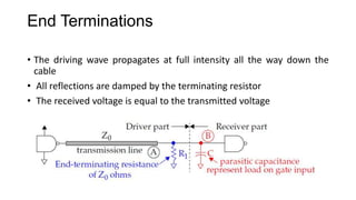
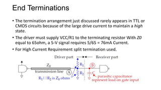


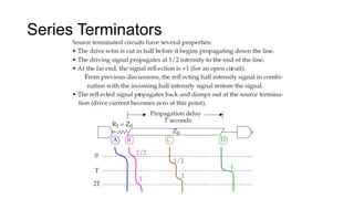


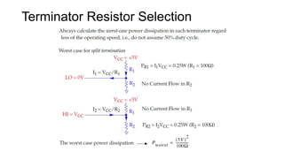
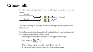
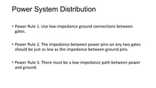
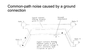
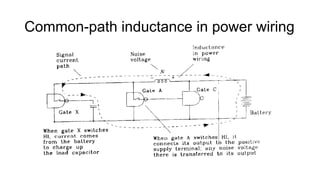
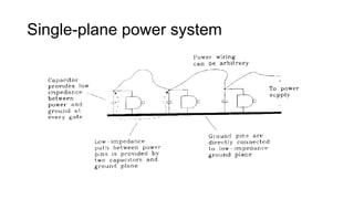
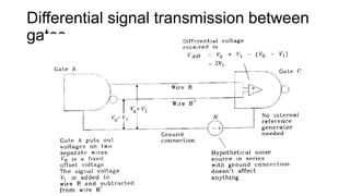
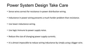


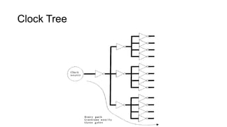
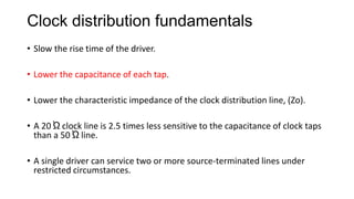
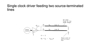
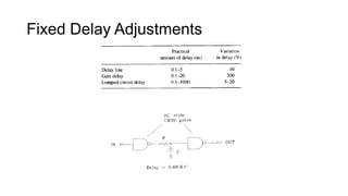


This document discusses various topics related to signal integrity in digital circuits, including: - Types of terminators for cables like end, series, and middle terminators. - Considerations for selecting terminator resistors like impedance matching and power handling. - Sources of cross-talk and techniques to reduce it. - Basics of power distribution systems including bypass capacitors and avoiding common path noise. - Fundamentals of clock distribution like minimizing skew and adjusting delays to meet timing requirements.