
Recommended
More Related Content
What's hot
What's hot (20)
Viewers also liked
Viewers also liked (20)
Similar to PFC Capacitors & Reactor brochure 3.2 mb
Similar to PFC Capacitors & Reactor brochure 3.2 mb (20)
Recently uploaded
Recently uploaded (20)
PFC Capacitors & Reactor brochure 3.2 mb
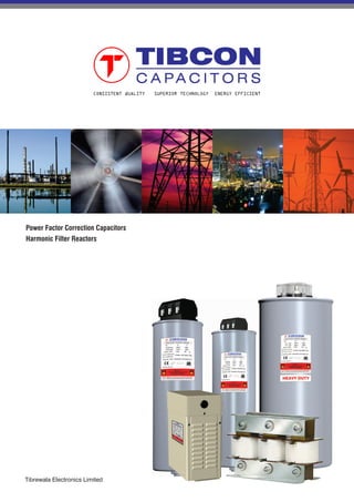
- 1. CONSISTENT QUALITY SUPERIOR TECHNOLOGY ENERGY EFFICIENT Power Factor Correction Capacitors Harmonic Filter Reactors Tibrewala Electronics Limited
- 2. About Us As one of the most renowned manufacturers of Capacitors and MPP Film in India, Tibrewala Electronics Limited (TEL) has successfully reached the elite 25 Million USD segment, having ventured to capture global markets across Asia, Africa, Australia, Europe and America. With an established presence of nearly three decades in the sector, TELhas become an invaluable resource in the manufacture of industrial machinery and domestic appliances of several reputed international brands and even defence electronics. Presently over 40% of our products are earmarked exclusively for export. With a staggering investment of over 10 Million USD today, we proudly stand on the threshold of phenomenal outbound growth, adding value to our partners, customers and vendors, strongly contributing to the nation's industrial strength. TEL has now become the world leader with its rich expertise and global standards.
- 3. Power Factor Correction Capacitors Unique Features Application The efficiency of power generation, transmission or conversion is improved when operated at near unity power factor. The least expensive way to achieve the same is by installing Power Factor Correction Capacitors. Power factor correction capacitors must be able to withstand high voltage transients and power line variations without breakdown. TIBCON PFC Capacitors are designed and manufactured for the most demanding applications and toughest ambient conditions. These capacitors are durable, safe, reliable and high performance solution for power factor correction in Industrial & semi-industrial application. TIBCON PFC Capacitors are made in accordance with Metallized Polypropelene technology with built-in SELF HEALING properties. We mastered this technology over a period of last 30 years and have the state of art manufacturing facility for metallization of the film. The elements are wound on fully automatic numerically controlled winding machine that ensures no corona discharge & ionization. The elements are housed in cylindrical shaped aluminum case with in built explosion proof safety device. • Compact Cylindrical Construction • 3 Phase - Delta Connection • Non-PCB Oil Encapsulation • High Temperature Withstanding Capacity • Self Healing Properties • Explosion Proof Design • Safe-Touch, Shock-Proof Terminals • Longer Life Expectancy • ECO-Friendly •Wide Range - Standard Duty, Heavy Duty & Super Heavy Duty • APFC Control Panels • Wind Turbines • Commercial Establishments • Industrial and Semi Industrial Applications • De-tuned and Tuned Harmonic Filters • Fixed Compensation ( Individual and Group) • Motors and Transformers • Welding • Furnaces Design & Construction IEC 60831-1&2 CM/L6098780 IS:13340 & 13341 Introduction Power Factor Correction Capacitors
- 4. Construction details of capacitors TIBCON manufacture three different types of PFC Capacitors - Standard Duty (400/415/440V), Heavy Duty (440/480V) and Super Heavy Duty (525/690V). The Standard Duty capacitors are manufactured by using standard thickness of dielectric material with heavy edge metallization. Heavy Duty Capacitors are manufactured with thicker dielectric material, housed in a bigger aluminium can. Super Heavy Duty Capacitors are made of Internal Series Metallized Film, which will reduce the terminal voltage at the capacitor level by half. This will help in drastic reduction of temperature with in the capacitor. Before Disconnection After Disconnection Explosion Proof Safety Device Sometimes Capacitors may explode due to very high voltages in repetitive peaks, which cannot be ‘self healed’ by the regenerative property. TIBCON Capacitors are provided with an internal Over-Pressure Disconnector, which disconnects the capacitor from the power source and prevents it from exploding. Construction Internal Series Metallized Film Plastic Film Range of PFC Capacitors Series Voltage Type Output 400V Cylindrical 1-50 KVAR Box Type 1-30 KVAR 415V Cylindrical 1-50 KVAR Box Type 1-30 KVAR 440V Cylindrical 1-50 KVAR Box Type 1-30 KVAR 440V Cylindrical 5-25 KVAR Box Type 5-25 KVAR 480V Cylindrical 5-30 KVAR Box Type 5-25 KVAR 525V Cylindrical 5-33 KVAR SUPER HEAVY Box Type 5-25 KVAR DUTY 690V Cylindrical 5-25 KVAR Box Type 5-25 KVAR STANDARD DUTY HEAVY DUTY Power Factor Correction Capacitors
- 5. Technical Specifications Power Factor Correction Capacitors ALUMINIUM CYLINDRICAL & MS BOX TYPE • Standard IEC 60831-1 & 2, IS :13340 PART 1 & 2 • Type MKP Cylindrical / MS Box • Rated Voltage 230-690 Volts • Rated Frequency 50/ 60 Hz • Maximum Over Voltage U Max U +10% 8 h in every 24 hN U +15% 30min in every 24 hN U + 20% 5 min in every 24 hN U + 30% 1 min in every 24 hN • Dielectric System Metallized Polypropylene film with Zn/Al alloy, slope profile, special edge (wave cut) • Losses <0.25 Watt/Kvar (Without Resistor) & <0.5 Watt/Kvar (With Resistor) • Protection Class Ip20 • Cooling Natural Air Cooled • Max Above Sea Level 4,000 Mtrs. • Case: Extruded Aluminum Can / Powder Coated MS Box • Discharge Resistor Special Design Internal Discharge. Resistance 50 V In Less Than 60 Sec • Execution Indoor • Tolerance On Capacitance -5% To +10% • Test Voltage Terminal To Terminal Type Test : 2.15 U , 10 Sec, Routine Test : 2.15 U , 2 SecN N • Test Voltage Terminal To Casing U ≤ 660 V: 3000V AC 10 Sec, U = 660 V :6000V AC 10 SecN N • Temperature Category -25°C / + 55°C (Class D) • Max Humidity 95% • Grounding And Mounting With M12 Stud At The Bottom Of Case • Mounting Position Vertical • Connection Three Phase Delta Connection (Single Phase on Request) • Protection Type Dry Type, Self-Healing, Internal Over Pressure Disconnector • Impregnant Non PCB, Biodegradable Natural Oil, High Viscosity Resin • Terminals Three phase terminal with electric shock protection (finger proof), designed for up to 25sq.mm cable termination, Double fast-on with cable ( <8kVAr) Tin Plated MS Studs for Box Type Capacitors SUPER HEAVY DUTY - CYLINDRICAL • Rated Reactive Power 5-33 KVAR Single Unit • Over Current 2.7 x In • Inrush Current 400 x In • Life Expectancy >2,00,000 Operating Hours • No. of Annual Switching Operations 20,000 HEAVY DUTY - CYLINDRICAL • Rated Reactive Power 5-30 KVAR Single Unit • Over Current 2.0 x In • Inrush Current 300 x In • Life Expectancy >1,50,000 Operating Hours • No. of Annual Switching Operations 10,000 STANDARD DUTY - CYLINDRICAL • Rated Reactive Power 0.25-50 KVAR Single Unit • Over Current 1.5 x In • Inrush Current 200 x In • Life Expectancy >1,00,000 Operating Hours • No. of Annual Switching Operations 5,000
- 6. Technical details - Cylindrical Type Power Factor Correction Capacitors STANDARD DUTY CAPACITORS - CYLINDRICAL TYPE . Rated Voltage 400/415/440V,50Hz, 3-Phase, Delta Connection 400V 380V 415V D x H (mm) (uF) Output KVAR Dimensions CapacitanceVoltage Current Fig Part Number 415V 400V 440V D x H (mm) (uF) Output KVAR Dimensions CapacitanceVoltage Current Fig Part Number 415 01.00 00.93 01.12 050.00 X 135 3x006.16 01.39 A PFC-01.00-3-415-50-C-00 415 02.00 01.86 02.25 050.00 X 135 3x012.32 02.78 A PFC-02.00-3-415-50-C-00 415 02.50 02.32 02.81 050.00 X 135 3x015.40 03.48 A PFC-02.50-3-415-50-C-00 415 05.00 04.65 05.62 063.50 X 155 3x030.80 06.95 A PFC-05.00-3-415-50-C-03 415 07.50 06.97 08.43 075.00 X 175 3x046.20 10.42 A PFC-07.50-3-415-50-C-10 415 10.00 09.29 11.24 075.00 X 210 3x061.60 13.90 B PFC-10.00-3-415-50-C-05 415 12.50 11.61 14.05 075.00 X 210 3x077.00 17.37 B PFC-12.50-3-415-50-C-05 415 15.00 13.94 16.86 085.00 X 210 3x092.40 20.85 B PFC-15.00-3-415-50-C-06 415 20.00 18.58 22.48 085.00 X 278 3x123.20 27.80 B PFC-20.00-3-415-50-C-14 415 20.00 18.58 22.48 095.00 X 210 3x123.20 27.80 B PFC-20.00-3-415-50-C-07 415 25.00 23.23 28.10 085.00 X 278 3x154.00 34.75 B PFC-25.00-3-415-50-C-14 415 25.00 23.23 28.10 095.00 X 247 3x154.00 34.75 B PFC-25.00-3-415-50-C-08 415 30.00 27.87 33.72 095.00 X 247 3x184.80 41.70 B PFC-30.00-3-415-50-C-08 415 40.00 37.11 44.96 116.00 X 247 3x246.40 55.60 B/C PFC-40.00-3-415-50-C-09 415 50.00 46.45 56.20 136.00 X 247 3x308.00 65.50 C PFC-50.00-3-415-50-C-12 440V 415V 400V D x H (mm) (uF) Output KVAR Dimensions CapacitanceVoltage Current Fig Part Number 440 00.50 00.44 00.41 050.00 X 135 3x002.74 00.66 A PFC-00.50-3-440-50-C-00 440 01.00 00.89 00.83 050.00 X 135 3x005.48 01.31 A PFC-01.00-3-440-50-C-00 440 02.00 01.78 01.65 050.00 X 135 3x010.96 02.62 A PFC-02.00-3-440-50-C-00 440 02.50 02.22 02.07 050.00 X 135 3x013.70 03.27 A PFC-02.50-3-440-50-C-00 440 03.00 02.67 02.48 050.00 X 155 3x016.44 03.93 A PFC-03.00-3-440-50-C-01 440 04.00 03.56 03.30 063.50 X 135 3x021.92 05.24 A PFC-04.00-3-440-50-C-02 440 05.00 04.45 04.15 063.50 X 155 3x027.40 06.55 A PFC-05.00-3-440-50-C-03 440 07.50 06.67 06.20 063.50 X 195 3x041.10 09.82 A PFC-07.50-3-440-50-C-04 440 08.33 07.41 06.87 063.50 X 195 3x045.64 10.90 A PFC-08.33-3-440-50-C-04 440 10.00 08.90 08.26 075.00 X 210 3x054.80 13.10 B PFC-10.00-3-440-50-C-05 440 12.50 11.12 10.33 075.00 X 210 3x068.50 16.40 B PFC-12.50-3-440-50-C-05 440 15.00 13.34 12.40 075.00 X 210 3x082.20 19.65 B PFC-15.00-3-440-50-C-05 440 20.00 17.79 16.53 085.00 X 210 3x109.60 26.20 B PFC-20.00-3-440-50-C-06 440 25.00 22.24 20.66 095.00 X 210 3x137.00 32.75 B PFC-25.00-3-440-50-C-07 440 28.00 24.91 23.11 085.00 X 278 3x153.44 36.68 B PFC-28.00-3-440-50-C-14 440 30.00 26.69 24.79 095.00 X 247 3x164.40 39.30 B PFC-30.00-3-440-50-C-08 440 40.00 35.58 33.06 116.00 X 247 3x219.20 52.40 B/C PFC-40.00-3-440-50-C-09 440 50.00 44.48 41.32 116.00 X 247 3x274.00 65.50 B/C PFC-50.00-3-440-50-C-09 400 01.00 00.90 01.08 063.50 X 087 3X006.64 01.44 A PFC-01.00-3-400-50-C-13 400 02.00 01.81 02.16 063.50 X 087 3X013.30 02.88 A PFC-02.00-3-400-50-C-13 400 02.50 02.26 02.69 063.50 X 087 3X016.60 03.60 A PFC-02.50-3-400-50-C-13 400 05.00 04.52 05.39 063.50 X 155 3x033.20 07.20 A PFC-05.00-3-400-50-C-03 400 07.50 06.76 08.07 075.00 X 175 3x049.70 10.80 B PFC-07.50-3-400-50-C-10 400 10.00 09.02 10.76 075.00 X 210 3x066.30 14.40 B PFC-10.00-3-400-50-C-05 400 12.50 11.28 13.46 085.00 X 210 3x082.90 18.00 B PFC-12.50-3-400-50-C-06 400 15.00 13.54 16.15 085.00 X 210 3x099.50 21.60 B PFC-15.00-3-400-50-C-06 400 20.00 18.04 21.53 085.00 X 278 3x132.60 28.80 B PFC-20.00-3-400-50-C-14 400 20.00 18.04 21.53 095.00 X 210 3x132.60 28.80 B PFC-20.00-3-400-50-C-07 400 25.00 22.56 26.92 085.00 X 278 3x165.80 36.00 B PFC-25.00-3-400-50-C-14 400 25.00 22.56 26.92 095.00 X 247 3x165.80 36.00 B PFC-25.00-3-400-50-C-08 400 30.00 27.06 32.29 116.00 X 247 3x198.90 43.20 B/C PFC-30.00-3-400-50-C-09 400 40.00 36.08 43.05 116.00 X 247 3x265.20 57.60 B/C PFC-40.00-3-400-50-C-09 400 50.00 45.10 53.81 136.00 X 247 3x331.50 72.00 C PFC-50.00-3-400-50-C-12 HEAVY DUTY CAPACITORS - CYLINDRICAL TYPE. Rated Voltage 440V, 50Hz, 3-Phase, Delta Connection 440V 415V 480V D x H (mm) (uF) Output KVAR Dimensions CapacitanceVoltage Current Fig Part Number 440 05.00 04.45 05.94 075.0 X 175 3x027.40 06.55 B PFC-05.00-3-440-50-CH-10 440 07.50 06.67 08.92 075.0 X 210 3x041.10 09.82 B PFC-07.50-3-440-50-CH-05 440 08.33 07.41 09.90 075.0 X 210 3x045.64 10.91 B PFC-08.33-3-440-50-CH-05 440 10.00 08.90 11.89 085.0 X 210 3x054.80 13.10 B PFC-10.00-3-440-50-CH-06 440 12.50 11.12 14.86 095.0 X 210 3x068.50 16.40 B PFC-12.50-3-440-50-CH-07 440 15.00 13.34 17.83 095.0 X 247 3x082.20 19.65 B PFC-15.00-3-440-50-CH-08 440 20.00 17.79 23.77 116.0 X 210 3x109.60 26.20 B/C PFC-20.00-3-440-50-CH-11 440 25.00 22.24 29.72 116.0 X 247 3x137.00 32.75 B/C PFC-25.00-3-440-50-CH-09 440 28.00 24.91 33.30 136.0 X 247 3x153.44 36.68 C PFC-28.00-3-440-50-CH-12 440 30.00 26.69 35.66 136.0 X 247 3x164.40 39.30 C PFC-30.00-3-440-50-CH-12
- 7. Technical details - Cylindrical Type Power Factor Correction Capacitors Fig - 'B' 44 Hexagonal Nut Star Washer ØD 16 M12 Ht Marking Details 37 S SS 31 Fig - 'A' Marking ØD 16 M12 Hexagonal Nut Star Washer Ht Details 50 6.5 12 7 SUPER HEAVY DUTY CAPACITORS - CYLINDRICAL TYPE. Rated Voltage 525/690V,50Hz, 3-Phase, Delta Connection NOTE : OTHER VOLTAGES, FREQUENCIES AND SIZES ARE AVAILABLE ON REQUEST HEAVY DUTY CAPACITORS - CYLINDRICAL TYPE. Rated Voltage 480V,50Hz, 3-Phase, Delta Connection 480V 440V 415V D x H (mm) (uF) Output KVAR Dimensions CapacitanceVoltage Current Fig Part Number 480 05.00 04.20 03.74 075.0 X 175 3x023.05 06.00 B PFC-05.00-3-480-50-CH-10 480 07.50 06.30 05.64 075.0 X 175 3x034.57 09.00 B PFC-07.50-3-480-50-CH-10 480 08.33 07.00 06.23 075.0 X 210 3x038.40 10.00 B PFC-08.33-3-480-50-CH-05 480 10.00 08.40 07.48 075.0 X 210 3x046.00 12.00 B PFC-10.00-3-480-50-CH-05 480 12.50 10.50 09.34 085.0 X 210 3x057.50 15.00 B PFC-12.50-3-480-50-CH-06 480 15.00 12.60 11.21 095.0 X 210 3x069.00 18.00 B PFC-15.00-3-480-50-CH-07 480 20.00 16.81 14.95 116.0 X 210 3x092.00 24.00 B/C PFC-20.00-3-480-50-CH-11 480 25.00 21.01 18.69 116.0 X 247 3x115.00 30.00 B/C PFC-25.00-3-480-50-CH-09 480 28.00 23.56 20.96 116.0 X 247 3x129.08 33.60 B/C PFC-28.00-3-480-50-CH-09 480 30.00 25.21 35.89 116.0 X 247 3x138.30 36.00 B/C PFC-30.00-3-480-50-CH-09 525V 480V 440V D x H (mm) (uF) Output KVAR Dimensions CapacitanceVoltage Current Fig Part Number 525 05.00 04.18 03.51 075.0 X 175 3x19.25 05.50 B PFC-05.00-3-525-50-CS-10 525 07.50 06.31 05.30 075.0 X 175 3x28.87 08.25 B PFC-07.50-3-525-50-CS-10 525 08.33 06.96 05.85 075.0 X 210 3x32.07 09.16 B PFC-08.33-3-525-50-CS-05 525 10.00 08.36 07.02 085.0 X 210 3x38.50 11.00 B PFC-10.00-3-525-50-CS-06 525 12.50 10.45 08.78 085.0 X 210 3x48.12 13.70 B PFC-12.50-3-525-50-CS-06 525 15.00 12.54 10.54 095.0 X 210 3x57.75 16.50 B PFC-15.00-3-525-50-CS-07 525 17.00 14.20 11.94 095.0 X 247 3x65.45 18.70 B PFC-17.00-3-525-50-CS-08 525 20.00 16.72 14.05 095.0 X 247 3x77.00 22.00 B PFC-20.00-3-525-50-CS-08 525 25.00 20.90 17.56 116.0 X 247 3x96.25 27.50 B/C PFC-25.00-3-525-50-CS-09 525 28.00 23.39 19.67 116.0 X 247 3x107.80 30.80 B/C PFC-28.00-3-525-50-CS-09 525 30.00 25.05 21.08 116.0 X 247 3x115.50 33.00 B/C PFC-30.00-3-525-50-CS-09 525 33.33 27.84 23.42 136.0 X 247 3x128.32 36.30 C PFC-33.33-3-525-50-CS-12 690V 660V 600V D x H (mm) (uF) Output KVAR Dimensions CapacitanceVoltage Current Fig Part Number 690 05.00 04.57 03.80 075.0 X 210 3x11.15 04.20 B PFC-05.00-3-690-50-CS-05 690 07.50 06.86 05.70 075.0 X 210 3x16.72 06.30 B PFC-07.50-3-690-50-CS-05 690 08.33 07.62 06.30 075.0 X 210 3x18.57 07.00 B PFC-08.33-3-690-50-CS-05 690 10.00 09.15 07.56 085.0 X 210 3x22.30 08.40 B PFC-10.00-3-690-50-CS-06 690 12.50 11.44 09.45 095.0 X 210 3x27.87 10.50 B PFC-12.50-3-690-50-CS-07 690 15.00 13.72 11.34 095.0 X 210 3x33.45 12.60 B PFC-15.00-3-690-50-CS-07 690 20.00 18.30 15.12 116.0 X 210 3x44.60 16.80 B/C PFC-20.00-3-690-50-CS-11 690 25.00 22.87 18.90 116.0 X 247 3x55.75 21.00 B/C PFC-25.00-3-690-50-CS-09
- 8. Technical Details - Box Type Power Factor Correction Capacitors Can Size Code Construction Frequency Hz Input Voltage No. of Phases Rating in KVAr Product PART NUMBER INDEX PFC- -3- -50- -1120.00 690 CS Output Kvar Dimensions (uF) LxWxH (mm) Voltage Capacitance Current (A) Part Number STANDARD MODULAR BOX TYPE. Rated Voltage 440V, 50Hz, 3-Phase, Delta Connection 440 05.0 175 x 056 x 260 3x027.40 06.55 PFC-05.00-3-440-50-BS-07 440 07.5 175 x 056 x 260 3x041.10 09.82 PFC-07.50-3-440-50-BS-07 440 10.0 212 x 076 x 320 3x054.80 13.10 PFC-10.00-3-440-50-BS-08 440 12.5 212 x 076 x 320 3x068.50 16.38 PFC-12.50-3-440-50-BS-08 440 15.0 212 x 076 x 320 3x082.20 19.65 PFC-15.00-3-440-50-BS-08 440 20.0 212 x 142 x 320 3x109.60 26.20 PFC-20.00-3-440-50-BS-09 440 25.0 212 x 142 x 320 3x137.00 32.75 PFC-25.00-3-440-50-BS-09 Output Kvar Dimensions (uF) LxWxH (mm) 440 01.0 108 x 38 x 123 3x005.48 01.31 PFC-01.00-3-440-50-BA-01 440 02.0 121 x 42 x 145 3x011.00 02.62 PFC-02.00-3-440-50-BA-02 440 03.0 121 x 42 x 145 3x016.44 03.93 PFC-03.00-3-440-50-BA-02 440 04.0 140 x 48 x 213 3x021.92 05.24 PFC-04.00-3-440-50-BA-03 440 05.0 140 x 48 x 213 3x027.40 06.55 PFC-05.00-3-440-50-BA-03 440 07.5 155 x 52 x 213 3x041.10 09.82 PFC-07.50-3-440-50-BA-04 440 10.0 155 x 52 x 213 3x054.80 13.10 PFC-10.00-3-440-50-BA-04 440 12.5 202 x 72 x 236 3x068.50 16.38 PFC-12.50-3-440-50-BA-05 440 15.0 202 x 72 x 236 3x082.20 19.65 PFC-15.00-3-440-50-BA-05 440 20.0 202 x 72 x 346 3x109.60 26.20 PFC-20.00-3-440-50-BA-06 440 25.0 202 x 72 x 346 3x137.00 32.75 PFC-25.00-3-440-50-BA-06 Voltage Capacitance Current (A) Part Number COMPACT MODEL BOX TYPE. Rated Voltage 440V, 50Hz, 3-Phase, Delta Connection Output Kvar Dimensions (uF) LxWxH (mm) Voltage Capacitance Current (A) Part Number HEAVY DUTY MODULAR BOX TYPE. Rated Voltage 440V, 50Hz, 3-Phase, Delta Connection 440 05.0 175 x 056 x 260 3x027.40 06.55 PFC-05.00-3-440-50-BH-07 440 07.5 212 x 076 x 320 3x041.10 09.82 PFC-07.50-3-440-50-BH-08 440 10.0 245 x 085 x 415 3x054.80 13.10 PFC-10.00-3-440-50-BH-10 440 12.5 245 x 085 x 415 3x068.50 16.38 PFC-12.50-3-440-50-BH-10 440 15.0 245 x 085 x 415 3x082.20 19.65 PFC-15.00-3-440-50-BH-10 440 20.0 245 x 170 x 415 3x109.60 26.20 PFC-20.00-3-440-50-BH-11 440 25.0 245 x 170 x 415 3x137.00 32.75 PFC-25.00-3-440-50-BH-11 NOTE : OTHER VOLTAGES, FREQUENCIES AND SIZES ARE AVAILABLE ON REQUEST PART NUMBER ABBREVIATION INDEX Construction Cylinder Dimension Box Dimensions Type Code Dia. x Ht.(mm) Code L x W x H(mm) Code Cylindrical C 050.0 X 135 0 108x038x123 1 Cyl.Heavy Duty CH 050.0 X 155 1 121x042x145 2 Cyl.Super Heavy Duty CS 063.5 X 135 2 140x048x213 3 Box Type - Compact/Agri BA 063.5 X 155 3 155x052x213 4 Box Type - Std Modular BS 063.5 X 195 4 202x072x236 5 Box Type - HD Modular BH 075.0 X 210 5 202x072x346 6 085.0 X 210 6 175x056x260 7 095.0 X 210 7 212x076x320 8 095.0 X 247 8 212x142x320 9 116.0 X 247 9 245x085x415 10 075.0 X 175 10 245x170x415 11 116.0 X 210 11 136.0 X 247 12 063.5 X 087 13 085.0 X 278 14
- 9. Harmonic Filter ReactorsIntroduction Influence of Harmonics & the need for Harmonic Filters Developments in modern semiconductor technology have led to a significant increase in the number of thyristor- and inverter fed loads. The growing use of these types of power electronic devices is causing an increasing level of harmonic distortion in the electrical system which very often leads to problems with capacitor installations. This can be controlled with the installation of Detuned Harmonic Reactors along with Capacitors, which will form Harmonic Filter. Installation of a Detuned Harmonic Filters is recommended, if your Harmonic generating load is more than 10% of the rated transformer power. We strongly advise to conduct a comprehensive mains analysis, including measurement of the harmonic content, before designing and installing your power factor correction equipment. TIBCON Detuned filter reactors are high quality reactors designed to be used in detuned power factor correction units. Our reactors are made with special air gap configurations and the latest winding technology and as a result, there is a very small power loss in operation with a high degree of reliability.An integrated bimetal switch is provided for additional operational reliability.These reactors are compatible with Indian & European standards. Features Ÿ Three phase, high permeable CRGO iron core, air cooled Ÿ High conductive Copper orAluminium Windings Ÿ High harmonic loading capability Ÿ Designed for very low power losses Ÿ Low noise emissions of ˂65dB Ÿ WagoTerminals for easyTermination in up to 20KVAR Ÿ Bus barTerminals for 25KVAR & above Ÿ Thermal Switch for overload protection Ÿ Vacuum impregnated varnish to ensure silent and moisture- immune operation Ÿ Manufactured under ISO 9000 quality management Ÿ Wide range from 5KVAR to 100KVAR both in Aluminium & Copper X Y ManufacturingStandard IS5553/IEC60289 Design 3PhaseIronCored Harmonics* V =0.5%V (dutycycle=100%)3 R V =6.0%V (dutycycle=100%)5 R V =5.0%V (dutycycle=100%)7 R V =3.5%V (dutycycle=100%)11 R V =3.0%V (dutycycle=100%)13 R 2 2 2 Effectivecurrent I = (I +I ....I )rms 1 3 13 Fundamentalcurrent I =1.06.I +(50Hzor60Hzcurrentofcapacitor)1 R RatedVoltage 400V&440VAC Detuning 5.67%,7%&14% Output 5-100KVAR Cooling AN NoiseLevel 65dB Enclosure IP00 TypeofCore(CoreMaterial) CRGO NominalLineFrequency 50Hz AmbientTemperature -10to+40°C StorageTemperature -25to+60°C TemperatureRiseLimited to 90ºC TemperatureProtection MicroSwitch (NC-140⁰C) InsulationClass H Separatecoiltestvoltage(HVTest) 3KV ToleranceofInductance ±5% Technical Data of Three Phase Reactors NOTE : OTHER VOLTAGES, FREQUENCIES AND SIZES ARE AVAILABLE ON REQUEST
- 10. Harmonic Filter ReactorsTechnical Details & Dimensions Reactor Rating 5KVAr 10KVAr 12.5KVAr 15KVAr 20KVAr 25KVAr 50KVAr 100KVAr Rated Inductance mH 6.12 3.06 2.45 2.04 1.53 1.22 0.61 0.31 RMS Current A 9.2 18.4 23.0 27.6 36.9 46.1 92.1 184.3 Terminal STUD TYPE STUD TYPE STUD TYPE STUD TYPE STUD TYPE BUS BAR BUS BAR BUS BAR COPPER REACTOR Weight (Approx) in Kgs 6 9 11 12 14 16 28 50 Length in mm (L) 180 180 180 180 210 210 240 270 Depth in mm (W) 70 85 95 100 80 90 100 120 Height in mm (H) 165 165 165 165 215 215 265 315 Mounting Dimension X 136 136 136 136 136 175 175 175 Mounting Dimension Y 60 75 85 90 80 90 110 140 Part No HRC3400-50-5.67-5 HRC3400-50-5.67-10 HRC3400-50-5.67-12.5 HRC3400-50-5.67-15 HRC3400-50-5.67-20 HRC3400-50-5.67-25 HRC3400-50-5.67-50 HRC3400-50-5.67-100 ALUMINIUM REACTOR Weight (Approx) in Kgs 6 8 12 11 12 12 29 46 Length in mm (L) 180 180 210 180 210 210 240 270 Depth in mm (W) 71 86 80 100 80 80 110 120 Height in mm (H) 165 165 215 165 215 215 265 315 Mounting Dimension X 136 136 136 136 136 175 175 175 Mounting Dimension Y 61 76 80 90 80 80 120 140 Part No HRA3400-50-5.67-5 HRA3400-50-5.67-10 HRA3400-50-5.67-12.5 HRA3400-50-5.67-15 HRA3400-50-5.67-20 HRA3400-50-5.67-25 HRA3400-50-5.67-50 HRA3400-50-5.67-100 400V, 50Hz, 5.67% REACTOR (f = 210 Hz, Linearity: L 0.95, L for current up to 2.08 x I1)r R Reactor Rating 5KVAr 10KVAr 12.5KVAr 15KVAr 20KVAr 25KVAr 50KVAr 100KVAr Rated Inductance mH 7.67 3.83 3.07 2.56 1.92 1.53 0.77 0.38 RMS Current A 8.2 16.4 20.5 24.6 32.8 41.0 81.9 163.9 Terminal STUD TYPE STUD TYPE STUD TYPE STUD TYPE STUD TYPE BUS BAR BUS BAR BUS BAR COPPER REACTOR Weight (Approx) in Kgs 6 9 10 12 14 13 23 40 Length in mm (L) 180 180 180 180 210 210 210 240 Depth in mm (W) 73 90 95 102 90 80 110 125 Height in mm (H) 150 150 150 165 195 195 215 265 Mounting Dimension X 136 136 136 136 136 175 175 175 Mounting Dimension Y 63 80 85 92 90 80 110 135 Part No HRC3400-50-7-5 HRC3400-50-7-10 HRC3400-50-7-12.5 HRC3400-50-7-15 HRC3400-50-7-20 HRC3400-50-7-25 HRC3400-50-7-50 HRC3400-50-7-100 ALUMINIUM REACTOR Weight (Approx) in Kgs 7 9 9 12 12 15 27 44 Length in mm (L) 180 180 180 210 210 210 240 240 Depth in mm (W) 80 95 95 81 81 90 105 150 Height in mm (H) 150 150 150 215 215 215 265 265 Mounting Dimension X 136 136 136 136 136 175 175 175 Mounting Dimension Y 70 85 85 81 81 90 115 160 Part No HRC3400-50-7-5 HRA3400-50-7-10 HRA3400-50-7-12.5 HRA3400-50-7-15 HRA3400-50-7-20 HRA3400-50-7-25 HRA3400-50-7-50 HRA3400-50-7-100 400V, 50Hz, 7% REACTOR (f = 189 Hz, Linearity: L 0.95, L for current up to 1.73 x I1)r R Reactor Rating 5KVAr 10KVAr 12.5KVAr 15KVAr 20KVAr 25KVAr 50KVAr 100KVAr Rated Inductance mH 16.58 8.29 6.63 5.53 4.15 3.32 1.66 0.83 RMS Current A 7.7 15.5 19.3 23.2 30.9 38.6 77.3 154.5 Terminal STUD TYPE STUD TYPE STUD TYPE STUD TYPE STUD TYPE BUS BAR BUS BAR BUS BAR COPPER REACTOR Weight (Approx) in Kgs 8 10 12 14 17 20 37 54 Length in mm (L) 180 180 180 180 210 210 240 240 Depth in mm (W) 80 90 102 110 95 105 125 160 Height in mm (H) 175 175 175 175 225 225 275 275 Mounting Dimension X 136 136 136 136 136 175 175 175 Mounting Dimension Y 70 80 92 100 95 105 135 170 Part No HRC3400-50-14.5-5 HRC3400-50-14-10 HRC3400-50-14-12.5 HRC3400-50-14-15 HRC3400-50-14-20 HRC3400-50-14-25 HRC3400-50-14-50 HRC3400-50-14-100 ALUMINIUM REACTOR Weight (Approx) in Kgs 8 11 12 16 15 18 35 65 Length in mm (L) 180 180 210 210 210 210 240 270 Depth in mm (W) 83 105 80 95 95 105 125 155 Height in mm (H) 175 175 225 225 225 225 275 325 Mounting Dimension X 136 136 136 136 136 175 175 175 Mounting Dimension Y 73 95 80 95 95 105 135 175 Part No HRA3400-50-14.5-5 HRA3400-50-14-10 HRA3400-50-14-12.5 HRA3400-50-14-15 HRA3400-50-14-20 HRA3400-50-14-25 HRA3400-50-14-50 HRA3400-50-14-100 400V, 50Hz, 14% REACTOR (f = 135 Hz, Linearity: L 0.95, L for current up to 1.37 x I1)r R
- 11. Harmonic Filter Reactors Reactor Rating 5KVAr 10KVAr 12.5KVAr 15KVAr 20KVAr 25KVAr 50KVAr 100KVAr Rated Inductance mH 7.41 3.7 2.96 2.47 1.85 1.48 0.74 0.37 RMS Current A 8.4 16.8 21 25.2 33.7 42.1 84.1 168.3 Terminal STUD TYPE STUD TYPE STUD TYPE STUD TYPE STUD TYPE BUS BAR BUS BAR BUS BAR COPPER REACTOR Weight (Approx) in Kgs 7 9 11 13 13 14 24 42 Length in mm (L) 180 180 180 180 180 180 240 240 Depth in mm (W) 76 90 100 105 100 110 90 130 Height in mm (H) 150 150 150 165 165 165 265 265 Mounting Dimension X 136 136 136 136 136 175 175 175 Mounting Dimension Y 66 80 90 95 90 100 100 140 Part No HRC3440-50-5.67-5 HRC3440-50-5.67-10 HRC3440-50-5.67-12.5 HRC3440-50-5.67-15 HRC3440-50-5.67-20 HRC3440-50-5.67-25 HRC3440-50-5.67-50 HRC3440-50-5.67-100 ALUMINIUM REACTOR Weight (Approx) in Kgs 7 9 10 11 13 16 24 51 Length in mm (L) 180 180 180 180 210 210 240 240 Depth in mm (W) 80 95 100 105 85 95 95 165 Height in mm (H) 150 150 165 165 215 215 265 265 Mounting Dimension X 136 136 136 136 136 175 175 175 Mounting Dimension Y 70 85 90 95 85 95 105 175 Part No HRA3440-50-5.67-5 HRA3440-50-5.67-10 HRA3440-50-5.67-12.5 HRA3440-50-5.67-15 HRA3440-50-5.67-20 HRA3440-50-5.67-25 HRA3440-50-5.67-50 HRA3440-50-5.67-100 440V, 50Hz, 5.67% REACTOR (f = 210 Hz, Linearity: L 0.95, L for current up to 2.08 x I1)r R Reactor Rating 5KVAr 10KVAr 12.5KVAr 15KVAr 20KVAr 25KVAr 50KVAr 100KVAr Rated Inductance mH 9.28 4.64 3.71 3.09 2.32 1.86 0.93 0.46 RMS Current A 7.4 14.9 18.6 22.3 29.8 37.2 74.5 149.0 Terminal STUD TYPE STUD TYPE STUD TYPE STUD TYPE STUD TYPE BUS BAR BUS BAR BUS BAR COPPER REACTOR Weight (Approx) in Kgs 7 8 10 10 13 14 25 42 Length in mm (L) 180 180 180 180 180 180 240 240 Depth in mm (W) 80 85 95 90 105 110 90 130 Height in mm (H) 150 150 150 165 165 165 265 265 Mounting Dimension X 136 136 136 136 136 175 175 175 Mounting Dimension Y 70 75 85 80 95 100 100 140 Part No HRC3440-50-7-5 HRC3440-50-7-10 HRC3440-50-7-12.5 HRC3440-50-7-15 HRC3440-50-7-20 HRC3440-50-7-25 HRC3440-50-7-50 HRC3440-50-7-100 ALUMINIUM REACTOR Weight (Approx) in Kgs 7 10 10 13 11 14 25 45 Length in mm (L) 180 180 180 210 210 210 240 240 Depth in mm (W) 80 100 95 86 77 86 100 150 Height in mm (H) 150 150 165 215 215 215 265 265 Mounting Dimension X 136 136 136 136 136 175 175 175 Mounting Dimension Y 70 90 85 86 77 86 110 160 Part No HRA3440-50-7-5 HRA3440-50-7-10 HRA3440-50-7-12.5 HRA3440-50-7-15 HRA3440-50-7-20 HRA3440-50-7-25 HRA3440-50-7-50 HRA3440-50-7-100 440V, 50Hz, 7% REACTOR (f = 189 Hz, Linearity: L 0.95, L for current up to 1.73 x I1)r R Reactor Rating 5KVAr 10KVAr 12.5KVAr 15KVAr 20KVAr 25KVAr 50KVAr 100KVAr Rated Inductance mH 20.06 10.03 8.03 6.69 5.02 4.01 2.01 1.00 RMS Current A 7.0 14.0 17.6 21.1 28.1 35.1 70.2 140.5 Terminal STUD TYPE STUD TYPE STUD TYPE STUD TYPE STUD TYPE BUS BAR BUS BAR BUS BAR COPPER REACTOR Weight (Approx) in Kgs 8 11 13 15 19 23 39 57 Length in mm (L) 180 180 180 180 210 210 240 240 Depth in mm (W) 83 95 110 115 100 115 130 165 Height in mm (H) 165 165 165 165 215 215 265 265 Mounting Dimension X 136 136 136 136 136 175 175 175 Mounting Dimension Y 73 85 100 105 100 115 140 175 Part No HRC3440-50-14.5-5 HRC3440-50-14.5-10 HRC3440-50-14.5-12.5 HRC3440-50-14.5-15 HRC3440-50-14.5-20 HRC3440-50-14.5-25 HRC3440-50-14.5-50 HRC3440-50-14.5-100 ALUMINIUM REACTOR Weight (Approx) in Kgs 9 12 13 17 17 21 37 67 Length in mm (L) 180 180 210 210 210 210 240 270 Depth in mm (W) 90 110 85 100 100 115 130 160 Height in mm (H) 165 165 215 215 215 215 265 315 Mounting Dimension X 136 136 136 136 136 175 175 175 Mounting Dimension Y 80 100 85 100 100 115 140 180 Part No HRA3440-50-14.5-5 HRA3440-50-14.5-10 HRA3440-50-14.5-12.5 HRA3440-50-14.5-15 HRA3440-50-14.5-20 HRA3440-50-14.5-25 HRA3440-50-14.5-50 HRA3440-50-14.5-100 440V, 50Hz, 14% REACTOR (f = 135 Hz, Linearity: L 0.95, L for current up to 1.37 x I1)r R Technical Details & Dimensions
- 12. © Reproduction, publication and dissemination of this technical literature and the contents therein without TIBREWALA ELECTRONICS LTD. prior written permission is strictly prohibited Contact TIBREWALA ELECTRONICS LTD. 6-56/2/40, Bombay Highway, Balanagar, Hyderabad-500 037, Telangana, INDIA. Tel : +91 40 23775351, Fax : +91 40 23775360 Email : info@tibcon.net; Visit us at : www.tibcon.net DISCLAIMER: The technical specifications and the product design are subject to change as per the evolving market requirements and product research. Customers may contact TibrewalaElectronics Limited forupdates on product design and technical specifications. The images shown in the brochure are only representation of the actual products. The colour,designandspecificationsoftheactualproductmayvary. CAPACITOR SELECTION CHART FOR HARMONIC FILTER APPLICATION 05.0 415V 5KVAR (440V 5.6KVAR) 10.0 415V 10KVAR (440V 11.2KVAR) 12.5 415V 12.5KVAR (440V 14KVAR) 15.0 415V 15KVAR (440V 16.8KVAR) 20.0 415V 20KVAR (440V 22.5KVAR) 25.0 415V 25KVAR (440V 28.1KVAR) 50.0 415V 25KVAR - 2NOS 100.0 415V 25KVAR - 4NOS 05.0 415V 5KVAR (440V 5.6KVAR) 10.0 415V 10KVAR (440V 11.2KVAR) 12.5 415V 12.5KVAR (440V 14KVAR) 15.0 415V 15KVAR (440V 16.8KVAR) 20.0 415V 20KVAR (440V 22.5KVAR) 25.0 415V 25KVAR (440V 28.1KVAR) 50.0 415V 25KVAR - 2NOS 100.0 415V 25KVAR - 4NOS 10.0 480V 12.5KVAR 12.5 480V 15KVAR 15.0 480V 20KVAR 20.0 480V 25KVAR 25.0 480V 30KVAR 50.0 480V 30KVAR - 2NOS 75.0 480V 30KVAR - 3NOS 100.0 480V 30KVAR - 4NOS KVAR Output 5.67% DETUNED HARMONIC FILTER APPLICATION INPUT VOLTAGE 400V AC KVAR Output 7% DETUNED HARMONIC FILTER APPLICATION KVAR Output 14% DETUNED HARMONIC FILTER APPLICATION 05.0 440V 5KVAR (480V 5.6KVAR) 10.0 440V 10KVAR (480V 11.2KVAR) 12.5 440V 12.5KVAR (480V 14KVAR) 15.0 440V 15KVAR (480V 16.8KVAR) 20.0 440V 20KVAR (480V 22.5KVAR) 25.0 440V 25KVAR (480V 28KVAR) 50.0 440V 25KVAR - 2NOS 100.0 440V 25KVAR - 4NOS 05.0 440V 5KVAR (480V 5.6KVAR) 10.0 440V 10KVAR (480V 11.2KVAR) 12.5 440V 12.5KVAR (480V 14KVAR) 15.0 440V 15KVAR (480V 16.8KVAR) 20.0 440V 20KVAR (480V 22.5KVAR) 25.0 440V 25KVAR (480V 28KVAR) 50.0 440V 25KVAR - 2NOS 100.0 440V 25KVAR - 4NOS 10.0 480V 12.5KVAR 12.5 480V 15KVAR 15.0 480V 20KVAR 20.0 480V 25KVAR 25.0 480V 28KVAR 50.0 480V 28KVAR - 2NOS 75.0 480V 28KVAR - 3NOS 100.0 480V 28KVAR - 4NOS KVAR Output 5.67% DETUNED HARMONIC FILTER APPLICATION INPUT VOLTAGE 415V AC KVAR Output 7% DETUNED HARMONIC FILTER APPLICATION KVAR Output 14% DETUNED HARMONIC FILTER APPLICATION 05.0 525V 7.5KVAR 10.0 525V 15KVAR 12.5 525V 17KVAR 15.0 525V 20KVAR 20.0 525V 28KVAR 25.0 525V 33.3KVAR 50.0 525V 33.3KVAR - 2NOS 100.0 525V 33.3KVAR - 4NOS 05.0 525V 7.5KVAR 10.0 525V 15KVAR 12.5 525V 17KVAR 15.0 525V 20KVAR 20.0 525V 28KVAR 25.0 525V 33.3KVAR 50.0 525V 33.3KVAR - 2NOS 100.0 525V 33.3KVAR - 4NOS 10.0 525V 12.5KVAR 12.5 525V 15KVAR 15.0 525V 20KVAR 20.0 525V 25KVAR 25.0 525V 30KVAR 50.0 525V 30KVAR - 2NOS 75.0 525V 30KVAR - 3NOS 100.0 525V 30KVAR - 4NOS KVAR Output 5.67% DETUNED HARMONIC FILTER APPLICATION INPUT VOLTAGE 440V AC KVAR Output 7% DETUNED HARMONIC FILTER APPLICATION KVAR Output 14% DETUNED HARMONIC FILTER APPLICATION