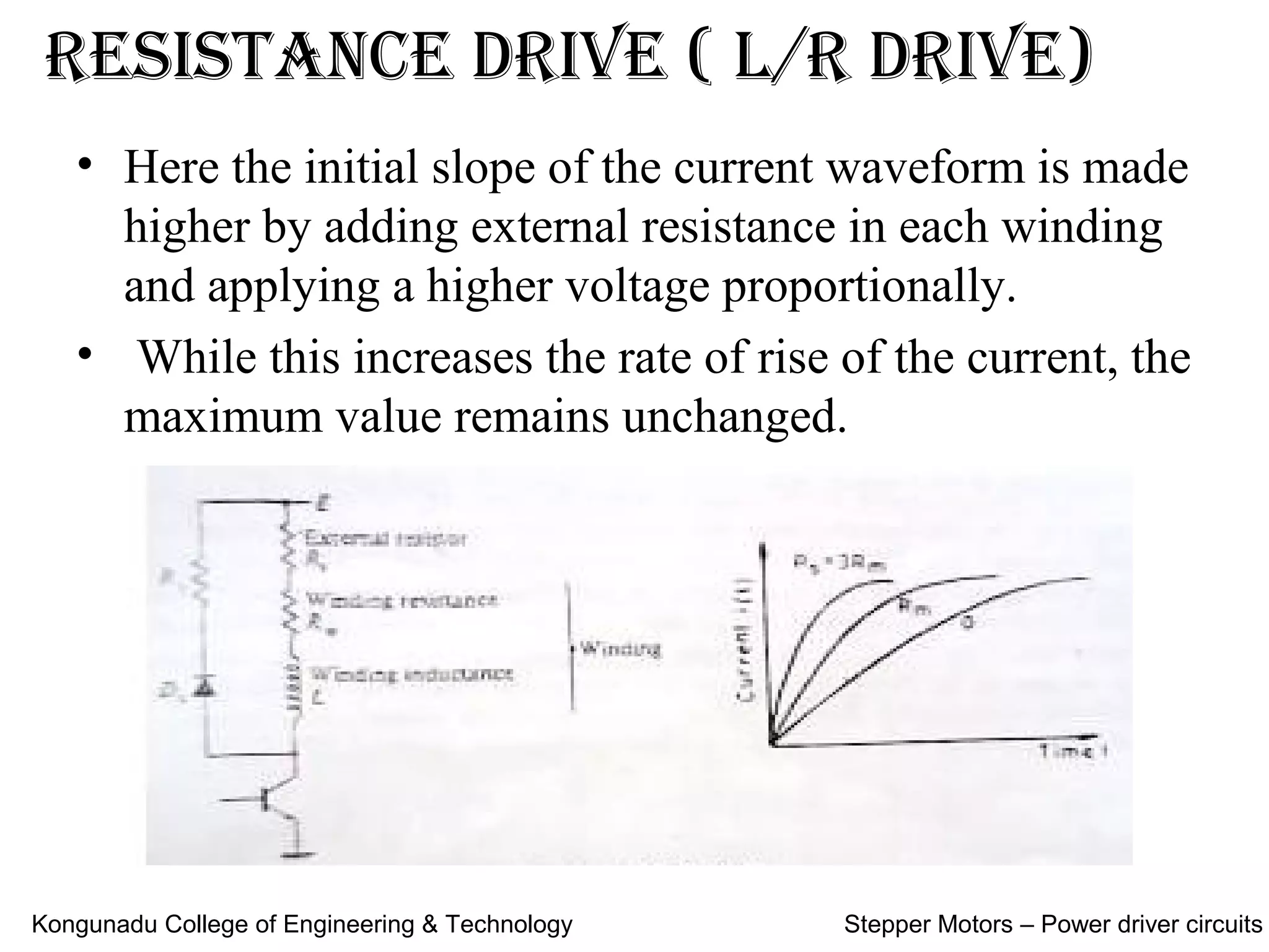
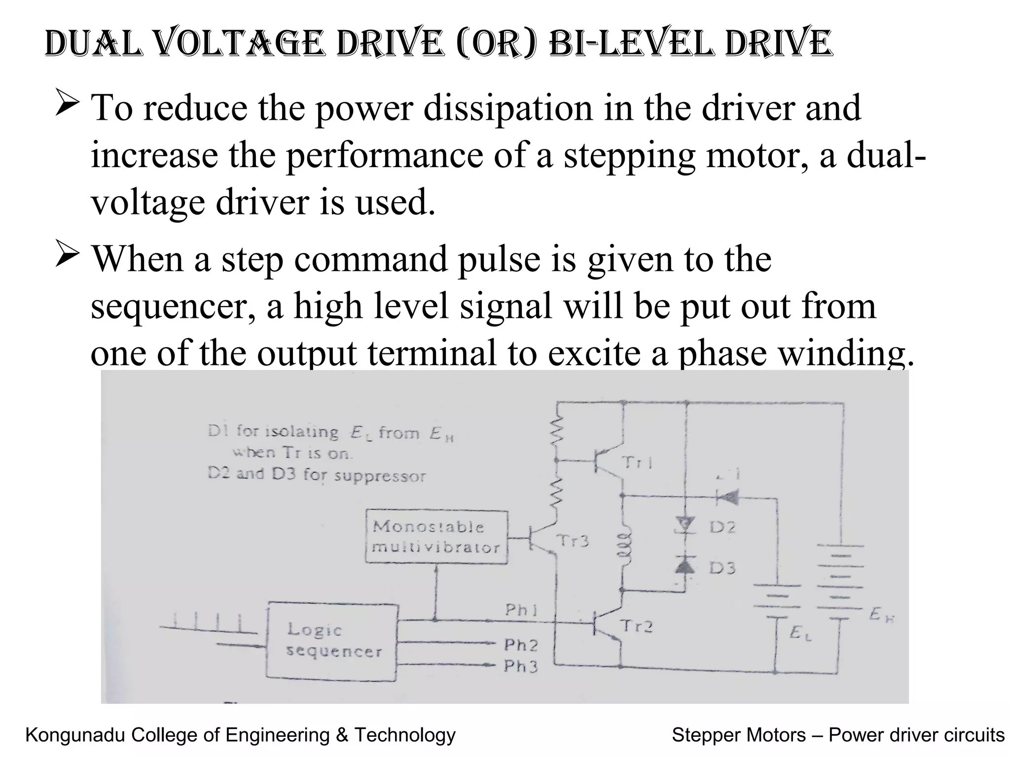
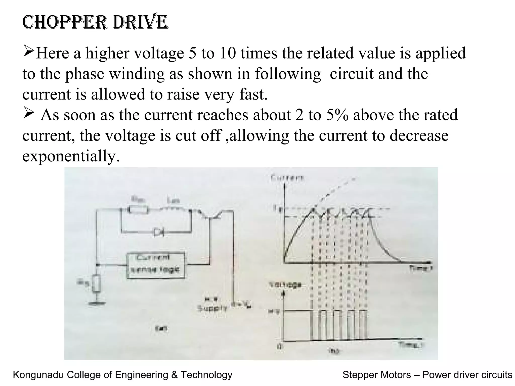
Stepper MotorS – power driver circuitS
Contents:
 Types of Power driver circuits
 Resistance drive (L/R drive)
 Dual voltage driver (or) Bi-level driver
 Chopper drive
 Applications of stepper motor
 References
Kongunadu College of Engineering & Technology Stepper Motors – Power driver circuits
typeS of power driver circuitS
 Resistance drive ( L/R drive)
 Dual voltage drive (or) Bi-level drive
 Chopper drive
 Applications of Stepper Motor
 References
Kongunadu College of Engineering & Technology Stepper Motors – Power driver circuits
reSiStance drive ( L/r drive)
• Here the initial slope of the current waveform is made
higher by adding external resistance in each winding
and applying a higher voltage proportionally.
• While this increases the rate of rise of the current, the
maximum value remains unchanged.
Kongunadu College of Engineering & Technology Stepper Motors – Power driver circuits
 To reduce the power dissipation in the driver and
increase the performance of a stepping motor, a dual-
voltage driver is used.
 When a step command pulse is given to the
sequencer, a high level signal will be put out from
one of the output terminal to excite a phase winding.
Dual voltage Drive (or) Bi-level Drive
Kongunadu College of Engineering & Technology Stepper Motors – Power driver circuits
On this signal both 1 and 2 are turned on, and the higher voltage
will be applied to the winding.
The diode is now reverse biased to isolate the lower voltage
supply.
 The current build up quickly due to the higher voltage.
The time constant of the monostable multivibrator is selected so
that transistor 1 is turned off when the winding current exceeds the
rated current by a little.
After the higher Voltage source is cut off the diode is forward
biased and the winding current is supplied from the lower voltage
supply.
Kongunadu College of Engineering & Technology Stepper Motors – Power driver circuits
Chopper Drive
Here a higher voltage 5 to 10 times the related value is applied
to the phase winding as shown in following circuit and the
current is allowed to raise very fast.
 As soon as the current reaches about 2 to 5% above the rated
current, the voltage is cut off ,allowing the current to decrease
exponentially.
Kongunadu College of Engineering & Technology Stepper Motors – Power driver circuits
Again as the current reaches some 2 to 5% below the
rated value, the voltage is applied again.
The process is repeated some 5-6 times within the ON
period before the phase is switched off.
During this period the current oscillates about the
rated value as shown in the circuit minor modification is
to chop the applied dc voltage at a high frequency of
around 1khz, with the desired duty cycle so as to obtain
the average on-state current equal to the rated value.
Kongunadu College of Engineering & Technology Stepper Motors – Power driver circuits
ApplicAtions of stepper motor
Floppy disc drives
Quartz watch
 Camera shutter operation
 Dot matrix and line printers
 Small tool application
 Robotics
Kongunadu College of Engineering & Technology Stepper Motors – Power driver circuits
REFERENCES
S.No Books / Web Sources
1. K.Venkataratnam, ‘Special Electrical Machines’, Universities Press (India) Private Limited, 2008
2. T.J.E. Miller, ‘Brushless Permanent Magnet and Reluctance Motor Drives’, Clarendon Press,Oxford, 1989.
3. T. Kenjo, ‘Stepping Motors and Their Microprocessor Controls’, Clarendon Press London, 1984.
4.
R.Krishnan, ‘Switched Reluctance Motor Drives – Modeling, Simulation, Analysis, Design andApplication’, CRC
Press, New York, 2001.
5. P.P. Aearnley, ‘Stepping Motors – A Guide to Motor Theory and Practice’, Peter Perengrinus ,London, 1982.
6. T. Kenjo and S. Nagamori, ‘Permanent Magnet and Brushless DC Motors’, Clarendon Press, London, 1988.
7. K.Dhayalini, “Special Electrical Machines,” Anuradha Publications, 2017.
8. Google and Wikipedia
Kongunadu College of Engineering & Technology Stepper Motors – Power driver circuits

Power driver circuits of stepper motor

  • 1.
    Stepper MotorS –power driver circuitS Contents:  Types of Power driver circuits  Resistance drive (L/R drive)  Dual voltage driver (or) Bi-level driver  Chopper drive  Applications of stepper motor  References Kongunadu College of Engineering & Technology Stepper Motors – Power driver circuits
  • 2.
    typeS of powerdriver circuitS  Resistance drive ( L/R drive)  Dual voltage drive (or) Bi-level drive  Chopper drive  Applications of Stepper Motor  References Kongunadu College of Engineering & Technology Stepper Motors – Power driver circuits
  • 3.
    reSiStance drive (L/r drive) • Here the initial slope of the current waveform is made higher by adding external resistance in each winding and applying a higher voltage proportionally. • While this increases the rate of rise of the current, the maximum value remains unchanged. Kongunadu College of Engineering & Technology Stepper Motors – Power driver circuits
  • 4.
     To reducethe power dissipation in the driver and increase the performance of a stepping motor, a dual- voltage driver is used.  When a step command pulse is given to the sequencer, a high level signal will be put out from one of the output terminal to excite a phase winding. Dual voltage Drive (or) Bi-level Drive Kongunadu College of Engineering & Technology Stepper Motors – Power driver circuits
  • 5.
    On this signalboth 1 and 2 are turned on, and the higher voltage will be applied to the winding. The diode is now reverse biased to isolate the lower voltage supply.  The current build up quickly due to the higher voltage. The time constant of the monostable multivibrator is selected so that transistor 1 is turned off when the winding current exceeds the rated current by a little. After the higher Voltage source is cut off the diode is forward biased and the winding current is supplied from the lower voltage supply. Kongunadu College of Engineering & Technology Stepper Motors – Power driver circuits
  • 6.
    Chopper Drive Here ahigher voltage 5 to 10 times the related value is applied to the phase winding as shown in following circuit and the current is allowed to raise very fast.  As soon as the current reaches about 2 to 5% above the rated current, the voltage is cut off ,allowing the current to decrease exponentially. Kongunadu College of Engineering & Technology Stepper Motors – Power driver circuits
  • 7.
    Again as thecurrent reaches some 2 to 5% below the rated value, the voltage is applied again. The process is repeated some 5-6 times within the ON period before the phase is switched off. During this period the current oscillates about the rated value as shown in the circuit minor modification is to chop the applied dc voltage at a high frequency of around 1khz, with the desired duty cycle so as to obtain the average on-state current equal to the rated value. Kongunadu College of Engineering & Technology Stepper Motors – Power driver circuits
  • 8.
    ApplicAtions of steppermotor Floppy disc drives Quartz watch  Camera shutter operation  Dot matrix and line printers  Small tool application  Robotics Kongunadu College of Engineering & Technology Stepper Motors – Power driver circuits
  • 9.
    REFERENCES S.No Books /Web Sources 1. K.Venkataratnam, ‘Special Electrical Machines’, Universities Press (India) Private Limited, 2008 2. T.J.E. Miller, ‘Brushless Permanent Magnet and Reluctance Motor Drives’, Clarendon Press,Oxford, 1989. 3. T. Kenjo, ‘Stepping Motors and Their Microprocessor Controls’, Clarendon Press London, 1984. 4. R.Krishnan, ‘Switched Reluctance Motor Drives – Modeling, Simulation, Analysis, Design andApplication’, CRC Press, New York, 2001. 5. P.P. Aearnley, ‘Stepping Motors – A Guide to Motor Theory and Practice’, Peter Perengrinus ,London, 1982. 6. T. Kenjo and S. Nagamori, ‘Permanent Magnet and Brushless DC Motors’, Clarendon Press, London, 1988. 7. K.Dhayalini, “Special Electrical Machines,” Anuradha Publications, 2017. 8. Google and Wikipedia Kongunadu College of Engineering & Technology Stepper Motors – Power driver circuits
  • 10.
    REFERENCES S.No Books /Web Sources 1. K.Venkataratnam, ‘Special Electrical Machines’, Universities Press (India) Private Limited, 2008 2. T.J.E. Miller, ‘Brushless Permanent Magnet and Reluctance Motor Drives’, Clarendon Press,Oxford, 1989. 3. T. Kenjo, ‘Stepping Motors and Their Microprocessor Controls’, Clarendon Press London, 1984. 4. R.Krishnan, ‘Switched Reluctance Motor Drives – Modeling, Simulation, Analysis, Design andApplication’, CRC Press, New York, 2001. 5. P.P. Aearnley, ‘Stepping Motors – A Guide to Motor Theory and Practice’, Peter Perengrinus ,London, 1982. 6. T. Kenjo and S. Nagamori, ‘Permanent Magnet and Brushless DC Motors’, Clarendon Press, London, 1988. 7. K.Dhayalini, “Special Electrical Machines,” Anuradha Publications, 2017. 8. Google and Wikipedia Kongunadu College of Engineering & Technology Stepper Motors – Power driver circuits