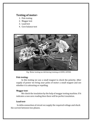
Coal India Limited Report (Khagendradewangan.blogspot.in)
1. A SUMMER TRAINING REPORT
ON
“WORKSHOP PRACTICES & RELATED MECHANICAL ACTIVITIES IN CENTRAL WORKSHOP, GEVRA”
By:-KHAGENDRA KUMAR DEWANGAN,13119040
MECH(7TH SEM) NIT RAIPUR, C.G.
3. ACKNOWLEDGEMENT
It gives me immense pleasure to come up with this report at the
end of my training. This training involved the collection and analysis
of information from a wide variety of sources and the efforts of
many people beyond me. Thus it would not have been possible to
achieve the results reported in this document without their help,
support and encouragement.
I would like to express my gratitude to the different dignitaries
of CEWS GEVRA for their co-operation and valuable help during my
Training Period.
I am equally grateful to all the employees of Mechanical
Department & Processing units who had provided me with adequate
data/information and support in spite of their hectic schedule.
I am thankful to my Institute “National Institute of Technology,
RAIPUR” for allowing me to do my summer training at COAL INDIA
(CEWS, S.E.C.L. GEVRA).
Regards,
KHAGENDRA KUMAR DEWANGAN
Mechanical Engg.
NIT RAIPUR, C.G.
4. DECLARATION
I KHAGENDRA KUMAR DEWANGAN, hereby declare that
this project report is the record of authentic work carried out by me
during of 31days period from 17/05/2015 onwards and has not been
submitted to any other University or Institute for the award of any
degree/diploma etc.
Signature of student
Name of the student: KHAGENDRA KUMAR DEWANGAN
Roll No. : 13119040
Branch : Mechanical
Semester : 7th
Institute : National Institute of Technology, Raipur
Course : Bachelor of Technology
5. CERTIFICATE
This is to certify that Mr. KHAGENDRA KUMAR DEWANGAN, S/O
RAMDAYAL DEWANGAN, a student of “National Institute of Technology,
Raipur” has successfully completed his summer training from 18/05/2016 to
17/06/2016 at CEWS, S.E.C.L. GEVRA.
During the period of his training program with us he was found punctual,
hardworking and inquisitive.
We wish him every success in life.
…………………………………..
GM (HRD CEWS, GEVRA)
6. PREFACE
This report is the work done during the summer training at CEWS,
S.E.C.L. GEVRA under the supervision of Mr. R. Prasad, GM (HRD CEWS, GEVRA).
The report shall give an overview of the different places that are visited
by me during my summer training with technical details.
I have tried my best to keep report yet technically correct. I hope I have
succeeded in my attempt.
KHAGENDRA KUMAR DEWANGAN
NIT RAIPUR, C.G.
7. ELECTRICAL REPAIR SHOP
INTRODUCTION-
In this shop AC/DC machines and Transformers are repaired and tested.
First inspection is to be done using various instruments and devices and after
that maintenance work are to be done. Then assembly of various parts and
components are done. Then delivery is done after the testing.
In the shop following machines are repaired-
1. AC/DC motors
2. AC/DC Generators
3. Transformers
MOTOR-
A motor is an electric device which converts
electrical energy to mechanical work.
Motor works on the phenomenon of
Fleming’s left hand rule.
Fig- A type of AC motor
On the basis of current we have two types of motors-
1. AC motor
2. DC motor
8. Types of AC motors we visited there are-
1. Induction motor
2. Slip ring motor
INDUCTION MOTORS-
In this motor stator winding is done and it is used for low load
applications.
SLIP RING MOTORS-
In this motors stator and rotor both winding is done and used for high
load applications and quick start.
Parts of motors-
ď‚· Yoke:
It is made up of cast iron (small machines) and cast steel (heavy
machines).
The functions of yoke are:
1. To carry main flux
2. To support the field poles
3. To give the mechanical support
ď‚· Field coils:
Enameled wire is used to do the coiling on the poles attached to yoke
to generate field-magnet .
ď‚· Armature core :
It is made up of silicon steel and its function is to accommodate the
conductors which offers low reluctance.
9. ď‚· Brush:
The function of brush is to make the electrical contact with the
commutator which moves with the rotating part.
Fig- Armature with Commutator used in DC machines
Types of DC motors-
1. Series motors
2. Shunt motors
3. Compound motors
Series motors-
The field winding is connected in series with the armature.
Shunt motors-
The field winding is connected in parallel with armature.
Compound motors-
It is subdivided into two types according to connection of field
windings. They are-
1. Short shunt
2. Long shunt
10. Testing of motor-
1. Pole testing
2. Meggar test
3. Load test
4. Core balance test
Fig- Motor testing we did during training at CEWS, GEVRA
Pole testing-
In this testing we use a small magnet to check the polarity. After
supply of power we bring near poles of motor a small magnet and see
whether it is attracting or repelling.
Meggar test-
We check the insulation by the help of meggar testing machine. If it
indicates a non zero reading then there will be perfect insulation.
Load test-
In delta connection of circuit we supply the required voltage and check
the current between two phases.
11. Fig-Tongue tester
Core balance test-
In star connection we supply current in two phases and keep open the
third phase and check the voltage drop among the phases and phase –neutral
voltages.
Fig- Tachometer for speed testing of rotor
12. Transformer-
It may be defined as the static electric device that converts one level
of voltage or current to other level without changing in frequency. There
are two types of winding- primary and secondary in transformers.
There are two types of transformer-
1. Step up
2. Step down
Fig- Transformer
Step up Transformer-
In this transformer the secondary will have more no. of turns or
windings than the primary.
Step down Transformer-
In this transformer the primary will have more no. of turns than the
secondary.
13. Testing of transformer-
Except pole testing all other are done same as in motors and one
more test-ratio test is done to ensure the perfect turn ratio.
Ratio test-
To ensure the turn ratio we provide the primary voltage and check
the voltage in secondary winding.
GENERATOR-
Generator is the Machine which convert mechanical energy into electrical
energy.
Types of Generator:-
1.AC Generator
2.DC Generator
Parts of Generator:-
ď‚· Rotor arm
ď‚· Armature
ď‚· Commutator
ď‚· Pole.
14. ENGINE SHOP
Here mainly the maintenance of various engine parts and components are
done.
There are mostly three types of engine used in whole area of Gevra project
mines.
1. KOMATSU-
ď‚· S6D170
ď‚· S6D140
ď‚· S6D125
ď‚· S6D110
Where,
S- supercharger
6- no. of cylinders used
D- direct injector type
170- bore diameter (in mm)
2. CUMMINS
ď‚· KTA38C
ď‚· KT1150
ď‚· NT855
ď‚· NTA855
Where,
K- series symbol
T- turbocharger
A- aftercooler
38C- cubic in displacement
855- cubic in displacement
15. 3. DDC (DETROIT DIESEL CONTROLLED)-
ď‚· SAAE-140
ď‚· SAAE3-140
Where,
S- supercharger
A- air to air
A- aftercooler
E- Emission
140- CID
SYSTEMS IN ENGINE
1. IGNITION SYSTEM
2. FUEL SYSTEM
3. AIR INTAKE OR EXHAUST SYSTEM
4. COOLING SYSTEM
5. LUBRICATION SYSTEM
IGNITION SYSTEM
Different types of ignition system used in various machine are
ď‚· Battery system
ď‚· Alternator
ď‚· Rectifier (current changer)
ď‚· Dynamo system
Self starter electrical energy mechanical
energy
FUEL SYSTEM
Types of fuel system-
ď‚· Gravity system-
we can use gravitational force for fuel feeding.
16. Exa.- bike system
ď‚· Forced feed system-
we can use a pump for feeding the fuel.
Exa.- P.T. pump system, F.I.P. pump system
Engine types on the basis of fuel-
ď‚· Petrol engine
ď‚· Diesel engine
ď‚· Kerosene engine
ď‚· CNG engine
AIR INTAKE OR EXHAUST SYSTEM
ď‚· Natural aspirated-
Simply atmospheric air comes in engine.
ď‚· Turbocharger-
It absorbs fresh air and send it to inlet. It works on the exhaust gas
temperature.
ď‚· Supercharger-
Works same as turbocharger except it uses engine power.
ď‚· Aftercooler-
Hot air is cooled and made dense.
18. COOLING SYSTEM
ď‚· Air cooling system-
we can use fins.
ď‚· Water cooling-
we can use radiator.
LUBRICATION SYSTEM
ď‚· Liquid system
ď‚· Solid system
ď‚· Semi solid system
Method of lubrication-
ď‚· Air type pump-
For simple oil requirement.
ď‚· Plunger type pump-
For less oil requirement.
ď‚· Splash type pump-
By crankshaft in oil sump.
SMOKES IN ENGINE
Due to unburnt hydrocarbon.
When oil and water and fuel mixes
When oil burns (due to damage of oil ring)
TYPESOFSMOKE
BLACK
WHITE
BLUE
20. HEAVY REPAIR SHOP
In this shop magnetorque, wheel motor, idler, roller, compressor and
motors are repaired.
Magnetorque–
It is used in shovel for hoisting (moving the bucket in upward and
downward direction). It consists 2 outer member, rotor and shaft (one outer
hollow and one inner solid shaft having independent rotation).
Outer hollow shaft connected to rotor and inner solid shaft connected to
outer member. In this machine the upper portion of magnetorque rotate when
we pass AC current through the slip ring. Due to magnetic induction the inner
part of this (armature) rotate with upper portion and in this way the torque is
produced and transmit to gears.
Fig-Magnetorque
21. Air compressor-
mainly reciprocating and screw compressor are used with different types
of machines. for high pressure requirement screw compressor (3kgf to 5kgf)
are used.
Fig- Screw Compressor
Screw compressor-
It consists of two rotors (male and female rotor) in a housing. Air from air
cleaner is pass through housing. Oil is used for lubrication. Compressed mixture
of oil and air is passed through separator, In which oil and compressed air get
separated.
This compressed air is used for different purpose. Bearing is used with
rotors to provide balance and smooth rotation.
Two types of clearance are provided between bearing and housing-
1. Discharge end clearance
2. Bearing end clearance
22. Fig-Compressor Housing
Inner diameter welding-
This type of welding is used to provide for refitting of idler, roller and
sprockets. Due to regular use of these, inner diameter get damaged so, MAG
(metal active gas) welding is used for refilling of materials. Carbon dioxide is
used as active gas which protects the welding zone from oxidation. Anti-spatter
spray is used to prevent the material from sticking on the workpiece.
23. Fig-Inner Diameter Welding
Outer diameter welding-
This type of welding is used to provide for refitting of idler, roller and
sprockets. Due to regular use of these, outer diameter get damaged so, this
welding is used for refilling of materials. flux is used to protects the welding
zone from oxidation. Anti-spatter spray is used to prevent the material from
sticking on the workpiece.
25. MACHINE & HT SHOP
This chapter describes machining processes with the capability of
producing parts that basically are round in shape. Typical products made are
as small as miniatures crews for the hinges of eyeglass frames and as large as
turbine shafts for hydroelectric power plants, rolls for rolling mills, and gun
barrels.
One of the most basic machining processes is turning, meaning that the
part is rotated while it is being machined. The starting material is generally a
work piece that has been made by other processes, such as casting, forging,
extrusion, drawing, or powder metallurgy.
The machines used in the shop are discussed below:
LATHE MACHINE :
FIGURE: LATHE MACHINE
The operations performed on lathe machine are:
26. ď‚· Turning:
To produce straight, conical, curved, or grooved work pieces such as
shafts, spindles, and pins.
ď‚· Facing:
To produce a flat surface at the end of the part and perpendicular to
its axis, useful for parts that are assembled with other components. Face
grooving produces grooves for applications such as O-ring seats.
ď‚· Boring:
To enlarge a hole or cylindrical cavity made by a previous process or
to produce circular internal grooves.
ď‚· Drilling:
To produce a hole (Fig. 23.1i), which may be followed by boring to
improve its dimensional accuracy and surface finish.
ď‚· Threading:
To produce external or internal threads.
ď‚· Knurling:
To produce a regularly shaped roughness on cylindrical surfaces,
as in making knobs and handles.
27. . FIGURE: Miscellaneous cutting operations that can be performed on a lathe.
The cutting operations just summarized typically are performed on a lathe,
which is available in a variety of designs, sizes, capacities, and computer
controlled features.
As shown in Fig, turning is performed at various
(1) rotational speeds, N, of the work piece clamped in a spindle,
(2) depths of cut, d, and
(3) feeds
depending on the work piece materials, cutting-tool materials, surface
finish and dimensional accuracy required, and characteristics of the machine
tool.
28. Tool Geometry:
The various angles in a single-point cutting tool have important functions
in machining operations. These angles are measured in a coordinate system
consisting of the three major axes of the tool shank, as can be seen in Fig. Note,
however, that these angles may be different, with respect to the work piece
after the tool is installed in the tool holder.
Rake angle is important in controlling both the direction of chip flow and
the strength of the tool tip. Positive rake angles improve the cutting operation
by reducing forces and temperatures. However, positive angles also result in a
small included angle of the tool tip, possibly leading to premature tool chipping
and failure, depending on the toughness of the tool material.
Side rake angle is more important than the back rake angle, although the
latter usually controls the direction of chip flow. For machining metals and
using carbide inserts, these angles typically are in the range from -5° to 5°.
Cutting-edge angle affects chip formation, tool strength, and cutting
forces to various degrees. Typically, the cutting-edge angle is around 15°.
Relief angle controls interference and rubbing at the tool-workpiece
interface. If it is too large, the tool tip may chip off; if it is too small, flank wear
may be excessive. Relief angles typically are 5 °.
Nose radius affects surface finish and tool-tip strength. The smaller the
nose radius (sharp tool), the rougher the surface finish of the workpiece and
29. the lower the strength of the tool. However, large nose radii can lead to tool
chatter.
SHAPER MACHINE:
Shaper is a reciprocating type of machine tool in which the ram moves
the cutting tool backwards and forwards in a straight line. The basic
components of shaper are shown in Fig. It is intended primarily to produce flat
surfaces. These surfaces may be horizontal, vertical, or inclined. In general, the
shaper can produce any surface composed of straight-line elements.
The principal of shaping operation is shown in Fig. Modern shapers can
also generate contoured surface as shown in Fig. 23.3. A shaper is used to
generate flat (plane) surfaces by means of a single point cutting tool similar to
a lathe tool.
31. SHAPER MECHANISM:
Crank and Slotted Link Mechanism-
In crank and slotted link mechanism (Fig. 23.6), the pinion receives its
motion from an individual motor or overhead line shaft and transmits the
motion or power to the bull gear. Bull gear is a large gear mounted within the
column. Speed of the bull gear may be changed by different combination of
gearing or by simply shifting the belt on the step cone pulley. A radial slide is
bolted to the centre of the bull gear.
This radial slide carries a sliding block into which the crank pin is fitted.
Rotation of the bull gear will cause the bush pin to revolve at a uniform speed.
Sliding block, which is mounted upon the crank pin is fitted within the slotted
link. This slotted link is also known as the rocker arm. It is pivoted at its bottom
end attached to the frame of the column.
The upper end of the rocker arm is forked and connected to the ram block
by a pin. With the rotation of bull gear, crank pin will rotate on the crank pin
circle, and simultaneously move up and down the slot in the slotted link giving
it a rocking movement, which is communicated to the ram. Thus the rotary
motion of the bull gear is converted to reciprocating motion of the ram.
FIGURE: SHAPER MECHANISM
32. SLOTTER MACHINE:
The slotter or slotting machine is also a reciprocating type of machine
tool similar to a shaper or a planer. It may be considered as a vertical shaper.
The chief difference between a shaper and a slotter is the direction of the
cutting action. The machine operates in a manner similar to the shaper,
however, the tool moves vertically rather than in a horizontal direction. The job
is held stationary. The slotter has a vertical ram and a hand or power operated
rotary table.
Fig-Slotter
33. MILLING MACHINE:
A milling machine is a machine tool that removes metal as the work is fed
against a rotating multipoint cutter. The milling cutter rotates at high speed and
it removes metal at a very fast rate with the help of multiple cutting edges. One
or more number of cutters canbe mounted simultaneously on the arbor of
milling machine. This is the reason that a milling machine finds wide
application in production work. Milling machine is used for machining flat
surfaces, contoured surfaces, surfaces of revolution, external and internal
threads, and helical surfaces of various cross-sections.
In milling machine, the metal is cut by means of a rotating cutter having
multiple cutting edges. For cutting operation, the workpiece is fed against the
rotary cutter. As the workpiece moves against the cutting edges of milling
cutter, metal is removed in form chips of trochoid shape. Machined surface is
formed in one or more passes of the work. The work to be machined is held in
a vice, a rotary table, a three jaw chuck, an index head, between centres, in a
special fixture or bolted to machine table. The rotatory speed of the cutting tool
and the feed rate of the workpiece depend upon the type of material being
machined.
34. Types of milling machine:
(a) Hand milling machine
(b) Horizontal milling machine
(c) Universal milling machine
(d) Vertical milling machine
Types of milling cutters:
35. HEAT TREATMENT SHOP
The various microstructures described thus far can be modified by heat-
treatment techniques-that is, by controlled heating and cooling of the alloys at
various rates. These treatments induce phase transformations that greatly
influence such mechanical properties as the strength, hardness, ductility,
toughness, and wear resistance of the alloys.
The effects of thermal treatment depend on the particular alloy, its
composition and microstructure, the degree of prior cold work, and the rates of
heating and cooling during heat treatment. The processes of recovery,
recrystallization, and grain growth are examples of thermal treatment,
involving changes in the grain structure of the alloy.
The following processes are done in this shop:
Hardening:
The structure can be made stronger by precipitation hardening. In this
process, the alloy is reheated to an intermediate temperature and then held
there for a period of time, during which precipitation takes place. The copper
atoms diffuse to nucleation sites and combine with aluminium atoms; this
process produces the theta phase, which forms as sub microscopic precipitates.
The increase in strength is due to increased resistance to dislocation movement
in the region of the precipitates.
Tempering:
If steels are hardened by heat treatment, then tempering or drawing is
used in order to reduce brittleness, increase ductility and toughness, and
reduce residual stresses. In tempering, the steel is heated to a specific
temperature, de- pending on its composition, and then cooled at a prescribed
rate. Alloy steels may undergo temper embrittlement, which is caused by the
segregation of impurities along the grain boundaries at temperatures between
480° and 590°C .
Annealing:
Annealing is a general term used to describe the restoration of a cold-
worked or heat-treated alloy to its original properties-for instance, to increase
ductility (and hence formability) and reduce hardness and strength, or to
36. modify the microstructure of the alloy. The annealing process is also used to
relieve residual stresses in a manufactured part, as well as to improve
machinability and dimensional stability.
The annealing process consists of the following steps:
I. Heating the work piece to a specific range of temperature in a furnace;
2. Holding it at that temperature for a period of time (soaking), and
3. Cooling the work piece, in air or in a furnace.
Normalizing:
In this process the metal is softenedby heating upto 850 degree(for steel)
i.e. temperature above critical temperature.
Case Hardening:
The heat-treatment processes described thus far involve microstructural
alterations and property changes in the hulk of the material or component by
means of through hardening. It is not desirable to through harden parts,
because a hard part lacks the necessary toughness for these applications; a
small surface crack could propagate rapidly through such a part and cause total
failure. In many cases, however, alteration of only the surface properties of a
part (hence, the term surface or case hardening) is desirable. This method is
particularly useful for improving resistance to surface indentation, fatigue, and
wear. Typical applications for case hardening are gear teeth, cams, shafts,
bearings, fasteners, pins, automotive clutch plates ,tools, and dies.
Types of furnace:
Batch Furnaces:
In a batch furnace, the parts to be heat treated are loaded into and
unloaded from the furnace in individual batches. This includes:
a. A box furnace is a horizontal rectangular chamber with one or two
access doors through which parts are loaded.
b. A pit furnace is a vertical pit below ground level into which the parts are
lowered. This type of furnace is particularly suitable for long parts, such
as rods, shafts, and tubing.
37. Continuous Furnace:
In this type of furnace, the parts to be heat treated move continuously
through the furnace on conveyors of various designs that use trays, belts,
chains, and other mechanisms. Continuous furnaces are suitable for high
production runs and can be designed and programmed so that complete heat-
treating cycles can be performed under tight control.
38. RECLAMATION SHOP
DESCRIPTION OF SHOP WORKING-
INTRODUCTION-
In this shop various types of maintenance works are performed-
1. Repair and treatment of shovel bucket and welding of these wear parts
2. Repairing of dozer bucket, shovel dragline shovel body.
3. Fitting of new plate in dragline to improvement of loading capacity.
4. Removal of corrosion particle attached to the body while stick in the
equipment and removal of soil and moisture content.
5. Welding of plate and attaching of plate in dragline, shovel bucket
Figure-Shovel dragline
39. DOZER SHOP
Parts which are used to repair in shop are followings-
1. Dozer wheel – D355, D155, D475, Wheel dozer 834B
2. Arm blade- D355, D155, D475
3. EK446/5 arm
4. Hydraulic excavation- ex300, BE1000, BE220,Bucket
5. Lift cylinder repair-
6. Tilt cylinder
7. Cutting edge joining-motor, Grader825 CAT 2GM
8. Track frame- D355, D155
9. Spray painting of all repaired sub assemblies.
Dozer wheel/Sprocket –D355,D155,D475, Wheel dozer 834B
Fig-sprocket wheel
40. Arm blade- D355, D155, D475 Dozers
Figure-dozer blade
Excavation- ex300, BE1000,BE220,Bucket
Figure- dozer arm
Figure-dumper arm
41. Track frame- D355, D155 Dozers
figure-Dozer bucket
In both Reclamation and Dozer shops welding is the major process for
repairing and maintenance.
The various welding processes, types, components and functions are
detailed below-
ARC WELDING-
Gas metal arc welding-
Arc welding is a type of welding that uses a welding power supply to
create an electric arc between an electrode and the base material to melt the
metals at the welding point. They can use either direct (DC) or alternating (AC)
current, and consumable or non-consumable electrodes. The welding region is
usually protected by some type of shielding gas, vapor, and/or slag. Power
supplies Engine driven welder capable of AC/DC welding.
To supply the electrical energy necessary for arc welding processes, a
number of different power supplies can be used. The most common
classification is constant current power supplies and constant voltage power
supplies. In arc welding, the voltage is directly related to the length of the arc,
and the current is related to the amount of heat input. Constant current power
supplies are most often used for manual welding processes such as gas
tungsten arc welding and shielded metal arc welding, because they maintain a
relatively constant current even as the voltage varies.
This is important because in manual welding, it can be difficult to hold the
electrode perfectly steady, and as a result, the arc length and thus voltage tend
to fluctuate. Constant voltage power supplies hold the voltage constant and
vary the current, and as a result, are most often used for automated welding
processes such as gas metal arc welding, flux cored arc welding, and submerged
arc welding. In these processes, arc length is kept constant, since any
42. fluctuation in the distance between the wire and the base material is quickly
rectified by a large change in current.
For example, if the wire and the base material get too close, the current
will rapidly increase, which in turn causes the heat to increase and the tip of the
wire to melt, returning it to its original separation distance. The direction of
current used in arc welding also plays an important role in welding.
Consumable electrode processes such as shielded metal arc welding and gas
metal arc welding generally use direct current, but the electrode can be charged
either positively or negatively. In welding, the positively charged anode will
have a greater heat concentration and, as a result, changing the polarity of the
electrode has an impact on weld properties. If the electrode is positively
charged, it will melt more quickly, increasing weld penetration and welding
speed. Alternatively, a negatively charged electrode results in more shallow
welds. Non-consumable electrode processes, such as gas tungsten arc welding,
can use either type of direct current (DC), as well as alternating current (AC).
With direct current however, because the electrode only creates the arc and
does not provide filler material, a positively charged electrode causes shallow
welds, while a negatively charged electrode makes deeper welds.
WELDING ELECTRODE-
In arc welding an electrode is used to conduct current through a
workpiece to fuse two pieces together. Depending upon the process, the
electrode is either consumable, in the case of gas metal arc welding or shielded
metal arc welding, or non-consumable, such as in gas tungsten arc welding. For
a direct current system the weld rod or stick may be a cathode for a filling type
weld or an anode for other welding processes. For an alternating current arc
welder the welding electrode would not be considered an anode or cathode.
43. Alternating current electrodes-
For electrical systems which use alternating current the electrodes are
the connections from the circuitry to the object to be acted upon by the electric
current but are not designated anode or cathode since the direction of flow of
the electrons changes periodically, usually many times per second.
Uses-
Electrodes are used to provide current through nonmetal objects to alter
them in numerous ways and to measure conductivity for numerous purposes.
Examples include:
• Electrodes for medical purposes, such as EEG, ECG, ECT, defibrillator
• Electrodes for electrophysiology techniques in biomedical research
• Electrodes for execution by the electric chair
• Electrodes for electroplating
• Electrodes for arc welding
• Electrodes for cathodic protection
• Electrodes for grounding
• Electrodes for chemical analysis using electrochemical methods
• Inert electrodes for electrolysis (made of platinum)
44. • Membrane electrode assembly
SUBMERGED ARC WELDING-
Submerged arc welding (SAW) is a common arc welding process.
Originally developed by the Linde - Union Carbide Company. It requires a non-
continuously fed consumable solid or tubular (flux cored) electrode. The
molten weld and the arc zone are protected from atmospheric contamination
by being “submerged” under a blanket of granular fusible flux consisting of
lime, silica, manganese oxide, calcium fluoride, and other compounds.
When molten, the flux becomes conductive, and provides a current path
between the electrode and the work. This thick layer of flux completely covers
the molten metal thus preventing spatter and sparks as well as suppressing
the intense ultraviolet radiation and fumes that are a part of the shielded
metal arc welding (SMAW) process.
SAW is normally operated in the automatic or mechanized mode, however,
semi-automatic (hand-held) SAW guns with pressurized or gravity flux feed
delivery are available. The process is normally limited to the flat or horizontal-
fillet welding positions (although horizontal groove position welds have been
done with a special arrangement to support the flux).
46. In oxy-fuel welding, a welding torch is used to weld metals. Welding metal
results when two pieces are heated to a temperature that produces a shared
pool of molten metal. The molten pool is generally supplied with additional
metal called filler. Filler material depends upon the metals to be welded.
In oxy-fuel cutting, a torch is used to heat metal to its kindling temperature.
A stream of oxygen is then trained on the metal, burning it into a metal oxide
that flows out of the kerf as slag.
Torches that do not mix fuel with oxygen (combining, instead, atmospheric
air) are not considered oxy-fuel torches and can typically be identified by a
single tank (Oxy-fuel cutting requires two isolated supplies, fuel and oxygen).
Most metals cannot be melted with a single-tank torch. As such, single-tank
torches are typically used only for soldering and brazing rather than welding.