Downloaded 174 times
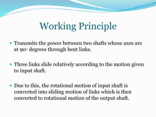
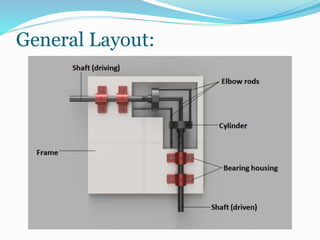
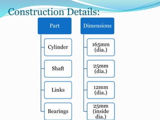
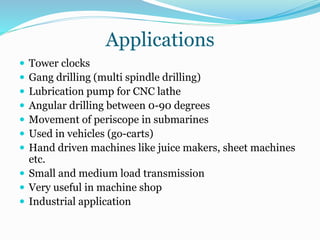
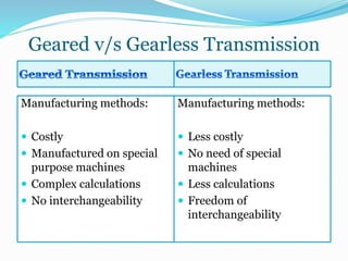
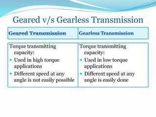
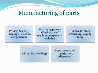
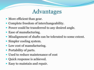
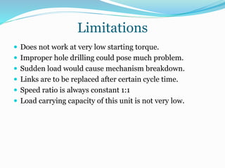


This document summarizes a gearless power transmission system. It discusses the need for gearless transmission to increase transmission efficiency. The gearless system uses bent links and sliders to transmit power between shafts at 90 degree angles without using gears. It has applications in tower clocks, drilling machines, and other applications where power needs to be transmitted at various angles. The gearless system has advantages over geared systems in cost, simplicity, and ability to transmit power at any angle. However, it is limited to lower torque applications compared to geared systems. Overall, the document presents the working, applications, advantages and limitations of a gearless transmission system.


![GEARLESS_POWER_ TRANSMISSION_PPT[1].pptx](https://cdn.slidesharecdn.com/ss_thumbnails/gearlesspowertransmissionppt1-250720203709-f8046d8f-thumbnail.jpg?width=640&height=640&fit=bounds)


