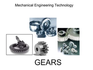
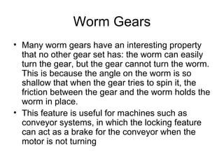
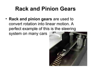
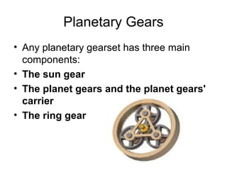
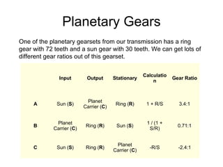
3. How Gears WorkHow Gears Work
• On any gear, the ratio is determined by
the distances from the center of the gear
to the point of contact. For instance, in a
device with two gears, if one gear is
twice the diameter of the other, the ratio
would be 2:1.
• One of the most primitive types of gears
we could look at would be a wheel with
wooden pegs sticking out of it.
4. Spur Gears
• Spur gears are the most common type of
gears. They have straight teeth, and are
mounted on parallel shafts. Sometimes, many
spur gears are used at once to create very
large gear reductions.
5. Uses of Spur GearUses of Spur Gear
• Spur gears are used in many devices that you
can see all over, like:
• electric screwdriver
• dancing monster
• oscillating sprinkler
• windup alarm clock
• washing machine
• clothes dryer.
6. Helical Gears
• The teeth on helical
gears are cut at an
angle to the face of the
gear.
7. Helical Gears
When two teeth on a helical gear system engage,
the contact starts at one end of the tooth and
gradually spreads as the gears rotate, until the
two teeth are in full engagement.
This gradual engagement makes helical gears
operate much more smoothly and quietly than
spur gears. For this reason, helical gears are
used in almost all car transmissions.
8. Helical Gears
Because of the angle of the teeth on helical gears,
they create a thrust load on the gear when they
mesh. Devices that use helical gears have
bearings that can support this thrust load.
• One interesting thing about helical gears is that
if the angles of the gear teeth are correct, they
can be mounted on perpendicular shafts,
adjusting the rotation angle by 90 degrees.
10. Bevel gears
• Bevel gears are useful when the direction of a
shaft's rotation needs to be changed. They are
usually mounted on shafts that are 90 degrees
apart, but can be designed to work at other
angles as well.
• The teeth on bevel gears can be straight, spiral
or hypoid. Straight bevel gear teeth actually
have the same problem as straight spur gear
teeth -- as each tooth engages, it impacts the
corresponding tooth all at once.
11. Bevel Gears
• Just like with spur gears, the solution to
this problem is to curve the gear teeth.
These spiral teeth engage just like helical
teeth: the contact starts at one end of the
gear and progressively spreads across the
whole tooth.
12. Bevel gears
• On straight and spiral bevel gears, the
shafts must be perpendicular to each
other, but they must also be in the same
plane. If you were to extend the two shafts
past the gears, they would intersect
13. Hypoid Gears
• The hypoid gear, on the other hand, can
engage with the axes in different planes. This
feature is used in many car differentials.
14. Hypoid
• The ring gear of the differential and the input
pinion gear are both hypoid. This allows the
input pinion to be mounted lower than the axis of
the ring gear.
• The Figure shows the input pinion engaging the
ring gear of the differential. Since the driveshaft
of the car is connected to the input pinion, this
also lowers the driveshaft. This means that the
driveshaft doesn't intrude into the passenger
compartment of the car as much, making more
room for people and cargo.
15. Worm Gears
• Worm gears are used when large gear reductions are
needed. It is common for worm gears to have reductions
of 20:1, and even up to 300:1 or greater.
16. Worm Gears
• Many worm gears have an interesting property
that no other gear set has: the worm can easily
turn the gear, but the gear cannot turn the worm.
This is because the angle on the worm is so
shallow that when the gear tries to spin it, the
friction between the gear and the worm holds the
worm in place.
• This feature is useful for machines such as
conveyor systems, in which the locking feature
can act as a brake for the conveyor when the
motor is not turning
17. Rack and Pinion Gears
• Rack and pinion gears are used to
convert rotation into linear motion. A
perfect example of this is the steering
system on many cars
18. Rack and Pinion Gears
• The steering wheel rotates a gear which
engages the rack. As the gear turns, it
slides the rack either to the right or left,
depending on which way you turn the
wheel
• Rack and pinion gears are also used in
some scales to turn the dial that displays
your weight.
19. Planetary Gears
• Any planetary gearset has three main
components:
• The sun gear
• The planet gears and the planet gears'
carrier
• The ring gear
20. Planetary Gears
• Each of these three components can be
the input, the output or can be held
stationary. Choosing which piece plays
which role determines the gear ratio for
the gearset. Let's take a look at a single
planetary gearset.
21. Planetary Gears
One of the planetary gearsets from our transmission has a ring
gear with 72 teeth and a sun gear with 30 teeth. We can get lots of
different gear ratios out of this gearset.
Input Output Stationary
Calculatio
n
Gear Ratio
A Sun (S)
Planet
Carrier (C)
Ring (R) 1 + R/S 3.4:1
B
Planet
Carrier (C)
Ring (R) Sun (S)
1 / (1 +
S/R)
0.71:1
C Sun (S) Ring (R)
Planet
Carrier (C)
-R/S -2.4:1
22. Planetary Gears
• Also, locking any two of the three components together
will lock up the whole device at a 1:1 gear reduction.
Notice that the first gear ratio listed above is a reduction
-- the output speed is slower than the input speed. The
second is an overdrive -- the output speed is faster than
the input speed. The last is a reduction again, but the
output direction is reversed.
Input Output Stationary
Calculatio
n
Gear Ratio
A Sun (S)
Planet
Carrier (C)
Ring (R) 1 + R/S 3.4:1
B
Planet
Carrier (C)
Ring (R) Sun (S)
1 / (1 +
S/R)
0.71:1
C Sun (S) Ring (R)
Planet
Carrier (C)
-R/S -2.4:1
23. Involute Gear Profiles
• On an involute profile gear tooth, the
contact point starts closer to one gear,
and as the gear spins, the contact point
moves away from that gear and toward
the other. If you were to follow the contact
point, it would describe a straight line that
starts near one gear and ends up near the
other. This means that the radius of the
contact point gets larger as the teeth
engage.