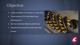
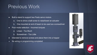
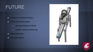
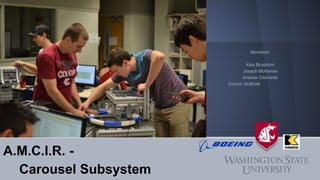
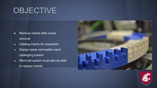
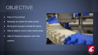
Automatic Mill Cutter Insert
Replacement
Members:
Kisa Brostrom
Joseph McKenna
Andrew Clements
Connor McBride
Josiah Wai
Nicholas Wood
Trevor Douglas
Aaron Thonney
Conor Moloney
Scott Olivares
OBJECTIVE
● End mills use 10,000+ inserts per week
used to cut titanium
● Boeing workers spend too much time and
effort preparing end mills
● System that automates the removal and
replacement of 85 cutter inserts
DESIGN APPROACH
● Split whole team into three
subsections
a. Screwdriver
b. Carousel
c. Programming
● Set high but realistic time/design
goals
● Transition into a complete integration
● Transition to programming
A.M.C.I.R. -
Programming and Electronics
Programming:
Josiah Wai
Conor Moloney
Integration:
Andrew Clements
Nicholas Wood
Connor McBride
Scott Olivares
Trevor Douglas
Joseph McKenna
Aaron Thonney
Kisa Brostrom
Objectives
● Learn the programming languages
○ TIA portal and FCT
● Program all the subsystems
○ Must work independently
○ Linear Actuator
■ Move tool
■ Rotate tool
○ Carousel
■ Rotate carousel
■ Actuate pneumatic arm
○ Screwdriver
■ Actuate screwdriver
■ Insert/remove screw
Previous Work
● Programming
o Linear actuator and carousel
 basic TIA programming
● Untested
 basic/plan
 Only actuator configured
o screwdriver
 No code
● Electronics
o Two PLCs
 Wired separately
o Grounded to bolts
o No sensors
o No HMI
Final Product
● Programming
o All systems home and position
correctly
o Linear Actuator
 both motors move tool
● rotational motor
underpowered
o Carousel
 Calibrated to rotate 1 cutting
insert per increment
 Jerkiness of movement
eliminated with higher power
motor.
o Screwdriver
 linear and rotational calibrated
 requires an I/O module to obtain
sufficient activation of all signal
commands (screw & unscrew)
Final Product ● Pneumatic Piston and Vacuum Generator
 piston and vacuum by solenoids through PLC
 2 pneumatic valves
● with 4 actuators
 Vacuum system improved by higher pressure
inlet supply
 Piston position improved by ordering FESTO
module for PID dynamic control. (Currently
operates with position control.)
● Electronics
o Overhauled electronics board
 PLCs interconnected and to HMI
 All components fused for safety
 Cleaned and organized wiring with
grounding/terminal blocks
 Grounded with aluminum plate
o Sensors for subsystems
Electronics Layout
● Components
o 24 VDC power supplies
o carousel, linear rail, and worm gear
motor controllers
o 2 PLCs
o HMI
o Communication module
o Distributed 16 signals I/O module
o ethernet cabling for
HMI/communication module/PLC
connections and (test phase only)
motor controller PC diagnostics.
o Wiring connection to all sensor and
actuators
Combined PLC Wiring Diagram
Future Work
● Programming
o Functionality and control-via-PLC/HMI demonstrated for every
system.
 requirements for full, independent automation:
● increase mechanical soundness w/ higher power
motors
● time in order to program
 proves mechanical soundness
o Full PLC-PLC communication
 Currently only a finite number of binary data can be
transferred. Requirements for full communication:
● time to learn Siemens communication protocol
● either I/O module or communication module
● Electronics
o Mount HMI and E-Stop
 Machine or water jet aluminum plate
o cover the electronics board
 Protect with a full non-metal housing
Bill of Materials
A.M.C.I.R. -
Screwdriver Subsystem
Members:
Trevor Douglas
Aaron Thonney
Nicholas Wood
Scott Olivares
Objective
● Loosen and fasten Torx screws in a cutter body
● Torque screws to 35 in-lbs without cross
threading errors
● No time constraints related to performance
● Integrate with carousel and cutter body linear
actuator
Previous Work
● Built a stand to support two Festo servo motors
a. One to drive a ball screw to raise/lower an actuator
b. One mounted at end of beam to be used as a screwdriver
● Poor motor selection - Incorrect torques
a. Linear - Too Much
b. Screwdriver - Too Little
● Intended to remove screws and place them into a hopper
● No wiring or programming completed
Final Product
● Redesign frame
○ New mounting brackets with ample adjustability
○ New Minitec linear actuator components
○ Couplers and adapters bought and manufactured
○ Adjustable feet added to new framing system
● Swap motors
○ Large servo motor - screwdriver
○ Small servo motor - linear actuator
● Flexible shaft to reduce load on cantilever beam
● Wired both servos to PLC, power, limit switch, and serial
ports
● Mounted limit switch for homing purposes
Bill of Materials
Problems
● Motors
○ Unable to read torque values
○ Lack of error detection
● Flexible shaft did not perform as
expected
● Linear actuator is imprecise
Future Recommendations
● Replace large servo motor with adequate stepper
motor and separate motor controller
○ Usable torque readings
○ Less weight
○ Direct drive
● More stability and repeatability
○ Gantry style frame
○ Purpose built linear actuator
A.M.C.I.R. -
Linear Actuator Subsystem
Members:
Kisa Brostrom
Joseph McKenna
Andrew Clements
Connor McBride
ITERATIONS
● Collaboration with all three subsections
● Create stability and support
o Add brackets which allow for no
movement
o Create a stand which aligns with
carousel and screwdriver
o Levels the linear actuator
● Troubleshoot system so system can be
programmed correctly
ITERATIONS
● Limit switches were
incorporated to home the
linear and rotational position of
the mill head mount
o solenoid
o touch
● Worm Gear Reinforced
o Mounts and shaft
remanufactured
o Addition of Bearing for
support
FINAL PRODUCT
● Rotational and Linear Motion
achieved
o Gear Box Added to Linear
● Integrated with HMI controls
● New Motor Mounts and Bearings
manufactured
● Design for Angle Stand and
Subsystem Connections finalized
FUTURE
● Addition of Vertical Actuator
● Worm Gear Refinement
o Stronger Material of Shaft
o Addition of Second Bearing
● Better Bearings
● Stronger Motors
A.M.C.I.R. -
Carousel Subsystem
Members:
Kisa Brostrom
Joseph McKenna
Andrew Clements
Connor McBride
OBJECTIVE
● Remove inserts after screw
removal
● Catalog inserts for inspection
● Design easily removable insert
cataloging system
● Removal system must also be able
to replace inserts
OBJECTIVE
● Ease of ring removal
● Redesign air system for better suction
● Be dynamic enough to handle 85 inserts
● Able to adapt to more or less inserts easily
● Allow for flawless integration with other
systems
PREVIOUS WORK
● System designed and manufactured which
o Spins carousel to store inserts
o Ejects screws through magazine
o Pneumatic actuator pushes inserts to and
from carousel and mill
● Plastic ring designed to hold 80 inserts
● System contained on Bosch frame as tabletop
● Little to no wiring or programming complete
ITERATIONS
● Top mounted components for easy access
● Components on top are hinged for ring replacement
● Redesigned ring with larger diameter to accommodate 85
inserts
● Designed suction head which conforms to insert perfectly
● Designed new pneumatic system for actuator
● Homing system designed
ITERATIONS
● Brackets for motors, carousel and homing
● Pneumatic valve system added
● Suction head casted
● Ring 3D printed
● Insert guide milled
● Bosch frame assembled
● Legs machined so system is level
● Feet added for stability
FINAL PRODUCT
● Top mounted components
● Best location of pneumatic actuator
● Hard resin casted suction head with soft silicone
surface
● Reed switch on actuator
● Dynamic mounts for ease of modification
● Stepper gear and track are compatible
● Hinge stops so system is in position
BILL OF MATERIALS
Part Quantity Unit Price per Unit Total Price
Carousel Ring 10 sections $5 $50
Suction head mold 3 sets $1 $3
Stepper gear 1 unit $1 $1
Hinges 2 sets 24.53 49.06
Waterjet brackets 10 brackets 4.00 40.00
Gussets 5 gussets 5.05 25.25
Bosch Tubing 6000 mm .01849 113.80
Total 282.11
FUTURE WORK
● Reliability of suction system
● Print/machine ring as one solid
part for complete accuracy
● Redesign of top mounting hinges
for repeatability
● Heavy duty bearing for carousel
track
● Accuracy of ring rotation
Final Product

Full Boeing

  • 1.
    Automatic Mill CutterInsert Replacement Members: Kisa Brostrom Joseph McKenna Andrew Clements Connor McBride Josiah Wai Nicholas Wood Trevor Douglas Aaron Thonney Conor Moloney Scott Olivares
  • 2.
    OBJECTIVE ● End millsuse 10,000+ inserts per week used to cut titanium ● Boeing workers spend too much time and effort preparing end mills ● System that automates the removal and replacement of 85 cutter inserts
  • 3.
    DESIGN APPROACH ● Splitwhole team into three subsections a. Screwdriver b. Carousel c. Programming ● Set high but realistic time/design goals ● Transition into a complete integration ● Transition to programming
  • 4.
    A.M.C.I.R. - Programming andElectronics Programming: Josiah Wai Conor Moloney Integration: Andrew Clements Nicholas Wood Connor McBride Scott Olivares Trevor Douglas Joseph McKenna Aaron Thonney Kisa Brostrom
  • 5.
    Objectives ● Learn theprogramming languages ○ TIA portal and FCT ● Program all the subsystems ○ Must work independently ○ Linear Actuator ■ Move tool ■ Rotate tool ○ Carousel ■ Rotate carousel ■ Actuate pneumatic arm ○ Screwdriver ■ Actuate screwdriver ■ Insert/remove screw
  • 6.
    Previous Work ● Programming oLinear actuator and carousel  basic TIA programming ● Untested  basic/plan  Only actuator configured o screwdriver  No code ● Electronics o Two PLCs  Wired separately o Grounded to bolts o No sensors o No HMI
  • 7.
    Final Product ● Programming oAll systems home and position correctly o Linear Actuator  both motors move tool ● rotational motor underpowered o Carousel  Calibrated to rotate 1 cutting insert per increment  Jerkiness of movement eliminated with higher power motor. o Screwdriver  linear and rotational calibrated  requires an I/O module to obtain sufficient activation of all signal commands (screw & unscrew)
  • 8.
    Final Product ●Pneumatic Piston and Vacuum Generator  piston and vacuum by solenoids through PLC  2 pneumatic valves ● with 4 actuators  Vacuum system improved by higher pressure inlet supply  Piston position improved by ordering FESTO module for PID dynamic control. (Currently operates with position control.) ● Electronics o Overhauled electronics board  PLCs interconnected and to HMI  All components fused for safety  Cleaned and organized wiring with grounding/terminal blocks  Grounded with aluminum plate o Sensors for subsystems
  • 9.
    Electronics Layout ● Components o24 VDC power supplies o carousel, linear rail, and worm gear motor controllers o 2 PLCs o HMI o Communication module o Distributed 16 signals I/O module o ethernet cabling for HMI/communication module/PLC connections and (test phase only) motor controller PC diagnostics. o Wiring connection to all sensor and actuators
  • 10.
  • 11.
    Future Work ● Programming oFunctionality and control-via-PLC/HMI demonstrated for every system.  requirements for full, independent automation: ● increase mechanical soundness w/ higher power motors ● time in order to program  proves mechanical soundness o Full PLC-PLC communication  Currently only a finite number of binary data can be transferred. Requirements for full communication: ● time to learn Siemens communication protocol ● either I/O module or communication module ● Electronics o Mount HMI and E-Stop  Machine or water jet aluminum plate o cover the electronics board  Protect with a full non-metal housing
  • 12.
  • 13.
    A.M.C.I.R. - Screwdriver Subsystem Members: TrevorDouglas Aaron Thonney Nicholas Wood Scott Olivares
  • 14.
    Objective ● Loosen andfasten Torx screws in a cutter body ● Torque screws to 35 in-lbs without cross threading errors ● No time constraints related to performance ● Integrate with carousel and cutter body linear actuator
  • 15.
    Previous Work ● Builta stand to support two Festo servo motors a. One to drive a ball screw to raise/lower an actuator b. One mounted at end of beam to be used as a screwdriver ● Poor motor selection - Incorrect torques a. Linear - Too Much b. Screwdriver - Too Little ● Intended to remove screws and place them into a hopper ● No wiring or programming completed
  • 16.
    Final Product ● Redesignframe ○ New mounting brackets with ample adjustability ○ New Minitec linear actuator components ○ Couplers and adapters bought and manufactured ○ Adjustable feet added to new framing system ● Swap motors ○ Large servo motor - screwdriver ○ Small servo motor - linear actuator ● Flexible shaft to reduce load on cantilever beam ● Wired both servos to PLC, power, limit switch, and serial ports ● Mounted limit switch for homing purposes
  • 17.
  • 18.
    Problems ● Motors ○ Unableto read torque values ○ Lack of error detection ● Flexible shaft did not perform as expected ● Linear actuator is imprecise
  • 19.
    Future Recommendations ● Replacelarge servo motor with adequate stepper motor and separate motor controller ○ Usable torque readings ○ Less weight ○ Direct drive ● More stability and repeatability ○ Gantry style frame ○ Purpose built linear actuator
  • 20.
    A.M.C.I.R. - Linear ActuatorSubsystem Members: Kisa Brostrom Joseph McKenna Andrew Clements Connor McBride
  • 21.
    ITERATIONS ● Collaboration withall three subsections ● Create stability and support o Add brackets which allow for no movement o Create a stand which aligns with carousel and screwdriver o Levels the linear actuator ● Troubleshoot system so system can be programmed correctly
  • 22.
    ITERATIONS ● Limit switcheswere incorporated to home the linear and rotational position of the mill head mount o solenoid o touch ● Worm Gear Reinforced o Mounts and shaft remanufactured o Addition of Bearing for support
  • 23.
    FINAL PRODUCT ● Rotationaland Linear Motion achieved o Gear Box Added to Linear ● Integrated with HMI controls ● New Motor Mounts and Bearings manufactured ● Design for Angle Stand and Subsystem Connections finalized
  • 24.
    FUTURE ● Addition ofVertical Actuator ● Worm Gear Refinement o Stronger Material of Shaft o Addition of Second Bearing ● Better Bearings ● Stronger Motors
  • 25.
    A.M.C.I.R. - Carousel Subsystem Members: KisaBrostrom Joseph McKenna Andrew Clements Connor McBride
  • 26.
    OBJECTIVE ● Remove insertsafter screw removal ● Catalog inserts for inspection ● Design easily removable insert cataloging system ● Removal system must also be able to replace inserts
  • 27.
    OBJECTIVE ● Ease ofring removal ● Redesign air system for better suction ● Be dynamic enough to handle 85 inserts ● Able to adapt to more or less inserts easily ● Allow for flawless integration with other systems
  • 28.
    PREVIOUS WORK ● Systemdesigned and manufactured which o Spins carousel to store inserts o Ejects screws through magazine o Pneumatic actuator pushes inserts to and from carousel and mill ● Plastic ring designed to hold 80 inserts ● System contained on Bosch frame as tabletop ● Little to no wiring or programming complete
  • 29.
    ITERATIONS ● Top mountedcomponents for easy access ● Components on top are hinged for ring replacement ● Redesigned ring with larger diameter to accommodate 85 inserts ● Designed suction head which conforms to insert perfectly ● Designed new pneumatic system for actuator ● Homing system designed
  • 30.
    ITERATIONS ● Brackets formotors, carousel and homing ● Pneumatic valve system added ● Suction head casted ● Ring 3D printed ● Insert guide milled ● Bosch frame assembled ● Legs machined so system is level ● Feet added for stability
  • 31.
    FINAL PRODUCT ● Topmounted components ● Best location of pneumatic actuator ● Hard resin casted suction head with soft silicone surface ● Reed switch on actuator ● Dynamic mounts for ease of modification ● Stepper gear and track are compatible ● Hinge stops so system is in position
  • 32.
    BILL OF MATERIALS PartQuantity Unit Price per Unit Total Price Carousel Ring 10 sections $5 $50 Suction head mold 3 sets $1 $3 Stepper gear 1 unit $1 $1 Hinges 2 sets 24.53 49.06 Waterjet brackets 10 brackets 4.00 40.00 Gussets 5 gussets 5.05 25.25 Bosch Tubing 6000 mm .01849 113.80 Total 282.11
  • 33.
    FUTURE WORK ● Reliabilityof suction system ● Print/machine ring as one solid part for complete accuracy ● Redesign of top mounting hinges for repeatability ● Heavy duty bearing for carousel track ● Accuracy of ring rotation
  • 34.