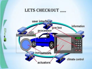
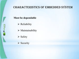
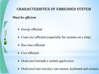
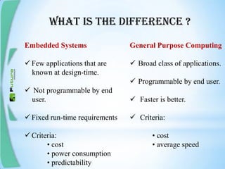
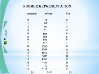
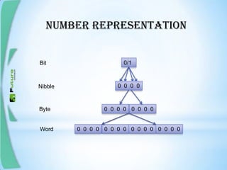
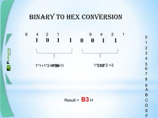
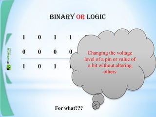
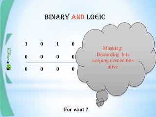
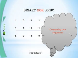
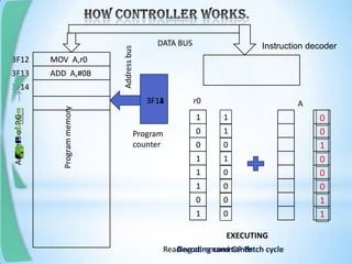
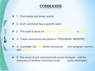
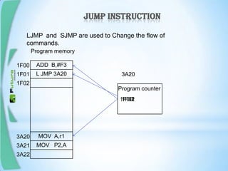
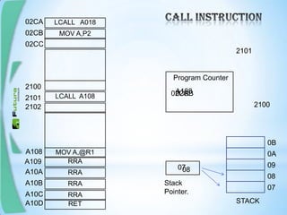
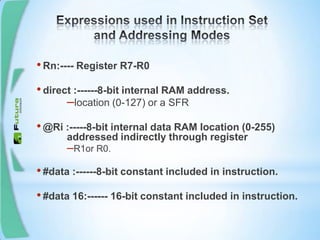
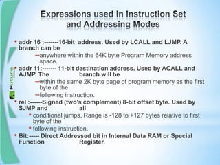
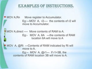
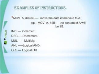
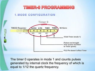
BASIC EMBEDDED SYSTEMTRAINING
It is an information processing systems embedded
into a larger product.
It can perform only that operations ,which it is
designed for
Lets checkout ,,,,,
Characteristics of embedded system
Must be dependable
 Reliability
 Maintainability
 Safety
 Security
Characteristics of embedded system
Must be efficient
 Energy efficient
 Code-size efficient (especially for systems on a chip)
 Run-time efficient
 Cost efficient
 Dedicated towards a certain application
 Dedicated user interface (no mouse, keyboard and screen).
What is the difference ?
Embedded Systems
 Few applications that are
known at design-time.
 Not programmable by end
user.
 Fixed run-time requirements
 Criteria:
• cost
• power consumption
• predictability
General Purpose Computing
 Broad class of applications.
 Programmable by end user.
 Faster is better.
 Criteria:
• cost
• average speed
DIGITAL FUNDAMENTALS
CHAPTER 1
let us begin with
NUMBER REPRESENTATION
D B H
0
2
1
4
3
5
6
8
7
9
10
13
11
12
14
15
0
01
10
11
100
101
111
110
1000
1010
1011
1100
1101
1110
1111
1001
0
2
1
4
3
5
6
8
7
9
A
C
B
D
E
F
ecimal inary ex
Base Base 2 Base
NUMBER REPRESENTATION
0/1Bit
0 0 0 0
0 0 0 00 0 0 0
0 0 0 00 0 0 0 0 0 0 00 0 0 0
Nibble
Byte
Word
Decimal to binary conversion
232
11
5
2
2
2
2
2
1
1
1
1
0
1
remainder
0
2310 = 2
BINARY TO DECIMAL CONVERSION
0 0 1 0 1 0 1 0
128 64 32 16 8 4 2 1
Binary value
Place value
0*128 0*11*20*41*80*161*320*64 +++++++ =42 Decimal value
BINARY TO HEX CONVERSION
1 0 1 1 0 0 1 1
LSBMSB
8 4 2 18 4 2 1
0
2
1
4
3
5
6
8
7
9
A
C
B
D
E
F
1*1+1*2 =31*1+1*2+1*8=11
Result = B3 H
BINARY NOT LOGIC
1’ = 0
0’ = 1
For what???
Binary or logic
1 0 1 1 0 0 0
0 0 0 0 0 1 1
1 0 1 1 0 1 1
Changing the voltage
level of a pin or value of
a bit without altering
others
For what???
Binary and logic
1 0 1 0 1 0 1 1
0 0 0 0 1 1 1 1
0 0 0 0 1 0 1 1
Masking:
Discarding bits
keeping needed bits
alive
For what ?
Binary xor logic
1 0 1 1 0 1 0 1
1 0 1 1 0 1 0 1
0 0 0 0 0 0 0 0
Comparing two
sequences
For what ?
TTL & CMOS
Port OR Out Put of
a Digital Circuit
5 Volt Pin of IC
1 at this O/P =5V with 60uA source
0 at this O/P = 0V with 1.6mA sink
(3.2 ma for P0)
GND pin of IC
+ve of 5V
-ve of 5V
R
R
MICROCONTROLLER GENERAL VIEW
MEMORY ORGANIZATION
User Ram
Register bank
Bit addressable Ram
r5 r4 r3 r2r6 r1 r0r7 00
7F
B0B7
R2
If r2=3C
1 0 10 0 00 1
07
80 TO FF are SFRs
MOV A,r0
ADD A,#0B
Instruction decoder
Programmemory
1
0
1
0
1
1
1
0
r0 A
Reading command OR Fetch cycle
DATA BUS
3F14
3F13
3F12
Decoding commands
EXECUTING
Program
counter
3F123F13
0
0
1
1
1
1
1
0
MOV A,r0
ADD A,#0B
3F14
Addressbus
AddressofP.G
1
0
1
1
0
0
0
0
0
1
0
0
0
1
1
0
 1 Commands are binary words.
 2. Each command has a specific work.
 3. This work is done on MEMORY, REGISTERS, or PORTS.
 4. These commands are stored in PROGRAM MEMORY.
 5. Controller will read these commands from program memory
and execute.
 6. The result of one command will not be changed until the
execution of another command at the same destination.
JUMPINSTRUCTION
LJMP and SJMP are used to Change the flow of commands.
L JMP 3A20
ADD B,#F3
MOV P2,A
MOV A,r1
1F00
1F01
1F02
3A20
3A21
3A22
1F001F01
3A20
1F02
Program counter
Program memory
LCALL A018
MOV A,P2
vv
LCALL A108
RRA
RRA
RRA
RRA
MOV A,@R1
Program Counter
A108
A109
A10A
2101
2102
2100
02CA
02CB
A10B
A10C
02CC
02CA
2100
02CB
2101
A108
07
Stack
Pointer.
07
08
0B
0A
09
STACKRETA10D
0708
1. Addressing is to which or where OR from which or
where the command should act.
eg: ADD A,#0B
a. A is the address where the ADD should
act. (Register addressing)
b. #0B is not an address. But this method is
immediate addressing.
•Rn:---- Register R7-R0
•direct :------8-bit internal RAM address.
–location (0-127) or a SFR
•@Ri :-----8-bit internal data RAM location (0-255)
addressed indirectly through register
–R1or R0.
•#data :------8-bit constant included in instruction.
•#data 16:------ 16-bit constant included in instruction.
• addr 16 :-------16-bit address. Used by LCALL and LJMP. A
branch can be
–anywhere within the 64K byte Program Memory address
space.
• addr 11:------- 11-bit destination address. Used by ACALL and
AJMP. The branch will be
–within the same 2K byte page of program memory as the first
byte of the
–following instruction.
• rel :------Signed (two’s complement) 8-bit offset byte. Used by
SJMP and all
• conditional jumps. Range is -128 to +127 bytes relative to first
byte of the
• following instruction.
• Bit:----- Direct Addressed bit in Internal Data RAM or Special
Function Register.
Examples of instructions.
 MOV A,Rn Move register to Accumulator.
Eg:---MOV A, r2---- the contents of r2 will
move to Accumulator.
 MOV A,direct ---- Move contents of RAM to A.
Eg:- MOV A, 6A ---the contents of RAM
location 6A will move to A
 MOV A, @Ri ---Contents of RAM indicated by Ri will
move to A.
Eg:-- MOV A, @r1--- If r1=3B, the
contents of RAM location 3B will move to A.
Examples of instructions.
*MOV A, #direct---- move the data immediate to A.
eg:-- MOV A, #2B-- the content of A will
be 2B.
INC --- increment.
DEC---- Decrement.
MUL---- Multiply.
ANL -----Logical AND.
ORL --- Logical OR
INPUT OUTPUT PORTS
*OPEN COLLECTOR – PORT0
OSCILLATOR
TIMER/COUNTER
SERIAL COMMUNICATION
8051 has 2 timers/counters T0 and T1
They can measure time, count intervals, and generate
baud rate.
If the content of the timer T0 is equal to 0 (T0=0) then
both registers will contain 0. If the timer number 2580
(hex), then the TH0 register (high byte) will contain the
number 25, while the TL0 register (low byte) will contain
number 80. (Upon reset Timer = 0000h).
GATE enables and disables Timer by means of a signal brought to the INTx pin
1 - Timer operates only if the INTx bit is set.
0 - Timer operates regardless of the logic state of the INTx bit.
C/T selects pulses to be counted up by the timer/counter :
1 - Timer counts pulses brought to the T0/T1pin
0 - Timer counts pulses from internal oscillator.
T1M1,T1M0 These two bits select the operational mode of the Timer0/1.
T1M1 T1M0 MODE DESCRIPTION
0 0 0 13-bit timer
0 1 1 16-bit timer
1 0 2 8-bit auto-reload
1 1 3 Split mode
This mode configures timer 0 as a 13-bit timer which consists of all 8 bits of TH0
and the lower 5 bits of TL0. As a result, the Timer 0 uses only 13 of 16 bits.
Mode 1 configures timer 0 as a 16-bit timer comprising all the bits of both
registers TH0 and TL0. That's why this is one of the most
commonly used modes.
TL0 register operates as a timer, while TH0 register stores the value from
which the counting starts.
Mode 3 configures timer 0 so that registers TL0 and TH0 operate as separate
8-bit timers. The TL0 timer turns into timer 0, while the TH0 timer turns into
timer 1.
TF1 bit is automatically set, on the Timer 1 overflow.
TR1 bit enables the Timer 1.
1 - Timer 1 is enabled.
0 - Timer 1 is disabled.
TF0 bit is automatically set, on the Timer 0 overflow.
TR0 bit enables the timer 0.
1 - Timer 0 is enabled.
0 - Timer 0 is disabled.
The timer 0 operates in mode 1 and counts pulses
generated by internal clock the frequency of which is
equal to 1/12 the quartz frequency.
The TR0 bit is set and the timer starts operation. If the quartz
crystal with frequency of 12MHz is embedded then its contents will
be incremented every microsecond.
Constant reading of timer is in efficient.
Only need to monitor overflow* (FFFF  0000)
When it occurs, the TF0 bit of the TCON register will be automatically set.
The state of this bit can be constantly checked from within the program or by
enabling an interrupt which will stop the main program execution when this
bit is set.
Required delay = 0.05 seconds (ie 50,000 machine cycles, 0.05/1uS)
Assuming XTAL Freq = 12Mhz
 Find value to be loaded into timer registers( TH & TL)
15536  3CB0  60176
Timer 1 only have UART circuitry in 8051

8051 training an interactive tutorial

  • 1.
  • 2.
    It is aninformation processing systems embedded into a larger product. It can perform only that operations ,which it is designed for
  • 3.
  • 4.
    Characteristics of embeddedsystem Must be dependable  Reliability  Maintainability  Safety  Security
  • 5.
    Characteristics of embeddedsystem Must be efficient  Energy efficient  Code-size efficient (especially for systems on a chip)  Run-time efficient  Cost efficient  Dedicated towards a certain application  Dedicated user interface (no mouse, keyboard and screen).
  • 6.
    What is thedifference ? Embedded Systems  Few applications that are known at design-time.  Not programmable by end user.  Fixed run-time requirements  Criteria: • cost • power consumption • predictability General Purpose Computing  Broad class of applications.  Programmable by end user.  Faster is better.  Criteria: • cost • average speed
  • 7.
  • 8.
    NUMBER REPRESENTATION D BH 0 2 1 4 3 5 6 8 7 9 10 13 11 12 14 15 0 01 10 11 100 101 111 110 1000 1010 1011 1100 1101 1110 1111 1001 0 2 1 4 3 5 6 8 7 9 A C B D E F ecimal inary ex Base Base 2 Base
  • 9.
    NUMBER REPRESENTATION 0/1Bit 0 00 0 0 0 0 00 0 0 0 0 0 0 00 0 0 0 0 0 0 00 0 0 0 Nibble Byte Word
  • 10.
    Decimal to binaryconversion 232 11 5 2 2 2 2 2 1 1 1 1 0 1 remainder 0 2310 = 2
  • 11.
    BINARY TO DECIMALCONVERSION 0 0 1 0 1 0 1 0 128 64 32 16 8 4 2 1 Binary value Place value 0*128 0*11*20*41*80*161*320*64 +++++++ =42 Decimal value
  • 12.
    BINARY TO HEXCONVERSION 1 0 1 1 0 0 1 1 LSBMSB 8 4 2 18 4 2 1 0 2 1 4 3 5 6 8 7 9 A C B D E F 1*1+1*2 =31*1+1*2+1*8=11 Result = B3 H
  • 13.
    BINARY NOT LOGIC 1’= 0 0’ = 1 For what???
  • 14.
    Binary or logic 10 1 1 0 0 0 0 0 0 0 0 1 1 1 0 1 1 0 1 1 Changing the voltage level of a pin or value of a bit without altering others For what???
  • 15.
    Binary and logic 10 1 0 1 0 1 1 0 0 0 0 1 1 1 1 0 0 0 0 1 0 1 1 Masking: Discarding bits keeping needed bits alive For what ?
  • 16.
    Binary xor logic 10 1 1 0 1 0 1 1 0 1 1 0 1 0 1 0 0 0 0 0 0 0 0 Comparing two sequences For what ?
  • 17.
  • 18.
    Port OR OutPut of a Digital Circuit 5 Volt Pin of IC 1 at this O/P =5V with 60uA source 0 at this O/P = 0V with 1.6mA sink (3.2 ma for P0) GND pin of IC +ve of 5V -ve of 5V R R
  • 19.
  • 20.
  • 21.
    User Ram Register bank Bitaddressable Ram r5 r4 r3 r2r6 r1 r0r7 00 7F B0B7 R2 If r2=3C 1 0 10 0 00 1 07 80 TO FF are SFRs
  • 22.
    MOV A,r0 ADD A,#0B Instructiondecoder Programmemory 1 0 1 0 1 1 1 0 r0 A Reading command OR Fetch cycle DATA BUS 3F14 3F13 3F12 Decoding commands EXECUTING Program counter 3F123F13 0 0 1 1 1 1 1 0 MOV A,r0 ADD A,#0B 3F14 Addressbus AddressofP.G 1 0 1 1 0 0 0 0 0 1 0 0 0 1 1 0
  • 23.
     1 Commandsare binary words.  2. Each command has a specific work.  3. This work is done on MEMORY, REGISTERS, or PORTS.  4. These commands are stored in PROGRAM MEMORY.  5. Controller will read these commands from program memory and execute.  6. The result of one command will not be changed until the execution of another command at the same destination.
  • 24.
    JUMPINSTRUCTION LJMP and SJMPare used to Change the flow of commands. L JMP 3A20 ADD B,#F3 MOV P2,A MOV A,r1 1F00 1F01 1F02 3A20 3A21 3A22 1F001F01 3A20 1F02 Program counter Program memory
  • 25.
    LCALL A018 MOV A,P2 vv LCALLA108 RRA RRA RRA RRA MOV A,@R1 Program Counter A108 A109 A10A 2101 2102 2100 02CA 02CB A10B A10C 02CC 02CA 2100 02CB 2101 A108 07 Stack Pointer. 07 08 0B 0A 09 STACKRETA10D 0708
  • 26.
    1. Addressing isto which or where OR from which or where the command should act. eg: ADD A,#0B a. A is the address where the ADD should act. (Register addressing) b. #0B is not an address. But this method is immediate addressing.
  • 27.
    •Rn:---- Register R7-R0 •direct:------8-bit internal RAM address. –location (0-127) or a SFR •@Ri :-----8-bit internal data RAM location (0-255) addressed indirectly through register –R1or R0. •#data :------8-bit constant included in instruction. •#data 16:------ 16-bit constant included in instruction.
  • 28.
    • addr 16:-------16-bit address. Used by LCALL and LJMP. A branch can be –anywhere within the 64K byte Program Memory address space. • addr 11:------- 11-bit destination address. Used by ACALL and AJMP. The branch will be –within the same 2K byte page of program memory as the first byte of the –following instruction. • rel :------Signed (two’s complement) 8-bit offset byte. Used by SJMP and all • conditional jumps. Range is -128 to +127 bytes relative to first byte of the • following instruction. • Bit:----- Direct Addressed bit in Internal Data RAM or Special Function Register.
  • 29.
    Examples of instructions. MOV A,Rn Move register to Accumulator. Eg:---MOV A, r2---- the contents of r2 will move to Accumulator.  MOV A,direct ---- Move contents of RAM to A. Eg:- MOV A, 6A ---the contents of RAM location 6A will move to A  MOV A, @Ri ---Contents of RAM indicated by Ri will move to A. Eg:-- MOV A, @r1--- If r1=3B, the contents of RAM location 3B will move to A.
  • 30.
    Examples of instructions. *MOVA, #direct---- move the data immediate to A. eg:-- MOV A, #2B-- the content of A will be 2B. INC --- increment. DEC---- Decrement. MUL---- Multiply. ANL -----Logical AND. ORL --- Logical OR
  • 31.
    INPUT OUTPUT PORTS *OPENCOLLECTOR – PORT0
  • 32.
  • 33.
  • 34.
  • 36.
    8051 has 2timers/counters T0 and T1 They can measure time, count intervals, and generate baud rate. If the content of the timer T0 is equal to 0 (T0=0) then both registers will contain 0. If the timer number 2580 (hex), then the TH0 register (high byte) will contain the number 25, while the TL0 register (low byte) will contain number 80. (Upon reset Timer = 0000h).
  • 37.
    GATE enables anddisables Timer by means of a signal brought to the INTx pin 1 - Timer operates only if the INTx bit is set. 0 - Timer operates regardless of the logic state of the INTx bit. C/T selects pulses to be counted up by the timer/counter : 1 - Timer counts pulses brought to the T0/T1pin 0 - Timer counts pulses from internal oscillator. T1M1,T1M0 These two bits select the operational mode of the Timer0/1. T1M1 T1M0 MODE DESCRIPTION 0 0 0 13-bit timer 0 1 1 16-bit timer 1 0 2 8-bit auto-reload 1 1 3 Split mode
  • 38.
    This mode configurestimer 0 as a 13-bit timer which consists of all 8 bits of TH0 and the lower 5 bits of TL0. As a result, the Timer 0 uses only 13 of 16 bits.
  • 39.
    Mode 1 configurestimer 0 as a 16-bit timer comprising all the bits of both registers TH0 and TL0. That's why this is one of the most commonly used modes.
  • 40.
    TL0 register operatesas a timer, while TH0 register stores the value from which the counting starts.
  • 41.
    Mode 3 configurestimer 0 so that registers TL0 and TH0 operate as separate 8-bit timers. The TL0 timer turns into timer 0, while the TH0 timer turns into timer 1.
  • 42.
    TF1 bit isautomatically set, on the Timer 1 overflow. TR1 bit enables the Timer 1. 1 - Timer 1 is enabled. 0 - Timer 1 is disabled. TF0 bit is automatically set, on the Timer 0 overflow. TR0 bit enables the timer 0. 1 - Timer 0 is enabled. 0 - Timer 0 is disabled.
  • 43.
    The timer 0operates in mode 1 and counts pulses generated by internal clock the frequency of which is equal to 1/12 the quartz frequency.
  • 44.
    The TR0 bitis set and the timer starts operation. If the quartz crystal with frequency of 12MHz is embedded then its contents will be incremented every microsecond.
  • 45.
    Constant reading oftimer is in efficient. Only need to monitor overflow* (FFFF  0000) When it occurs, the TF0 bit of the TCON register will be automatically set. The state of this bit can be constantly checked from within the program or by enabling an interrupt which will stop the main program execution when this bit is set.
  • 46.
    Required delay =0.05 seconds (ie 50,000 machine cycles, 0.05/1uS) Assuming XTAL Freq = 12Mhz  Find value to be loaded into timer registers( TH & TL) 15536  3CB0  60176
  • 47.
    Timer 1 onlyhave UART circuitry in 8051