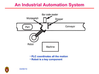
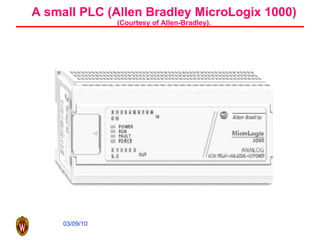
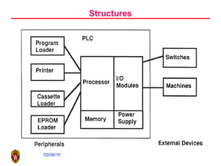
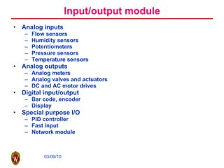
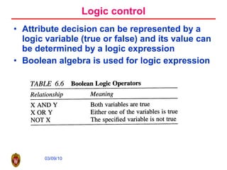
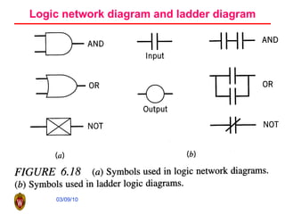
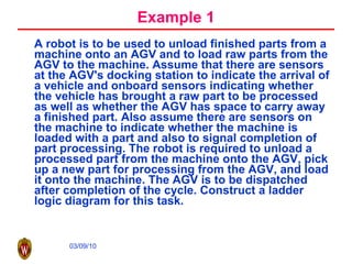
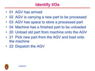
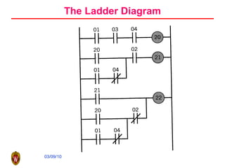
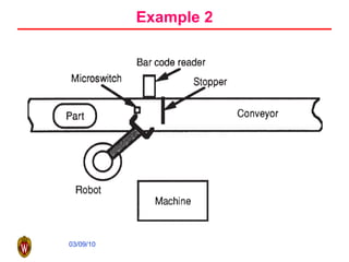
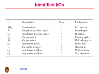
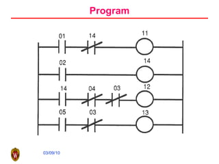
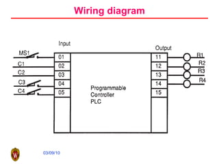
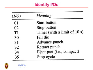
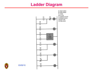
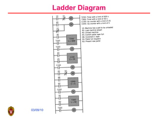
Programmable Logic Controller and Robotics
An Industrial Automation System PLC coordinates all the motion Robot is a key component
A small PLC (Allen Bradley MicroLogix 1000) (Courtesy of Allen-Bradley).
Definition of PLC PLC is a digitally operating electronic apparatus which uses a programmable memory for the internal storage of instructions by implementing specific functions such as logic sequencing, timing, counting, and arithmetic to control, through digital or analog input/output modules, various types of machines or processes. Modern PLC can be viewed as specialized computer Specialized in logic control Handle harsh and noisy environment
Structures
Input/output module Analog inputs Flow sensors Humidity sensors Potentiometers Pressure sensors Temperature sensors Analog outputs Analog meters Analog valves and actuators DC and AC motor drives Digital input/output Bar code, encoder Display Special purpose I/O PID controller Fast input Network module
Memory ROM RAM PROM EPROM etc
Peripherals Operator console Printer Simulator EPROM loader Network communication PC based programming software
Functions of PLC Relay Timer and counter Program control Arithmetic Data manipulation Data transfer Others, such as sequencers
A Relay
A counter
Counter timing diagram (the count value is 5)
A timer
Timer timing diagram (the timing value is 5)
Logic control Control actions are taken by making decisions depending on the values associated with various inputs or variables and the control logic in the program. Decisions by attributes (go-nogo decision) Is the machine turned on? Is the gate to the work cell open? Has the AGV arrived at the docking station? Decision by variables How deep is the hole? What is the cutting speed? What is the required surface finish? How many parts are to be made?
Logic control Attribute decision can be represented by a logic variable (true or false) and its value can be determined by a logic expression Boolean algebra is used for logic expression
Logic network diagram and ladder diagram
Example 1 A robot is to be used to unload finished parts from a machine onto an AGV and to load raw parts from the AGV to the machine. Assume that there are sensors at the AGV's docking station to indicate the arrival of a vehicle and onboard sensors indicating whether the vehicle has brought a raw part to be processed as well as whether the AGV has space to carry away a finished part. Also assume there are sensors on the machine to indicate whether the machine is loaded with a part and also to signal completion of part processing. The robot is required to unload a processed part from the machine onto the AGV, pick up a new part for processing from the AGV, and load it onto the machine. The AGV is to be dispatched after completion of the cycle. Construct a ladder logic diagram for this task.
Identify I/Os 01  AGV has arrived 02  AGV is carrying a new part to be processed 03  AGV has space to store a processed part 04  Machine has a finished part to be unloaded 20  Unload old part from machine onto the AGV 21  Pick new part from the AGV and load onto the machine 22  Dispatch the AGV
The Ladder Diagram
Features of Ladder Diagram A ladder logic diagram is made up of inputs and outputs connected according to the appropriate logic.  Each rung in the ladder represents a set of logical relationships between the inputs that leads to a particular output.  The output from one rung of the ladder could be used as an input in another rung of the same ladder.  Except when special provisions are made, it is considered that all rungs in a given ladder logic diagram are executed simultaneously, so the order of the rungs on the ladder in general does not matter.
PLC scan
Example 2
Identified I/Os
Program
Wiring diagram
Example 3 During the powder metallurgy process, a punch is used to press blended metal powder into a compact inside a die. A pushbutton is used to start the process. When the start button is pressed, the die is filled with powder. The punch is then advanced and it applies pressure to the powder for a duration of 10 s, after which it is retracted. The pressed compact is then ejected from the die and the cycle repeats. The cycle can be interrupted by pressing a stop button. If the stop button is pressed, the punch is required to retract (if it had been advanced) before the process is stopped. We are required to construct a ladder logic diagram for this task.
Identify I/Os
Ladder Diagram
Example 4 This example illustrates the use of both the timing and counting functions. Consider a production line in which parts requiring processing are brought to a machine by a conveyor. A robot is used to load parts from the conveyor onto the machine and, after the part has been processed, unload the part from the machine and place it on a pallet. The cycle time for processing each part is 10 min. The robot is to palletize the parts by placing 125 parts on each pallet. The parts are to be arranged on the pallet in five layers of 25 parts each. Once a pallet is complete, it is dispatched and a new pallet is started. An allowance of 30 s is to be made for pallet dispatching and presentation of a new pallet. Construct a ladder logic diagram to effect the required control.
Identified I/Os 10 Machine has a part to be unloaded 30 Load machine with a new part 40 Unload a process part from the machine 45 The current pallet layer is full 48 Increment layer being palletized by 1 50 The pallet is full-dispatch 60 Present a new pallet C100 Up counter with limit set to 25 C200 Up counter with limit set to 5 T250 Timer with limit set to 600 s T300 Timer with limit set to 30 s
Ladder Diagram
Design methods for ladder diagram
Truth table
Ladder diagram for Example 10.2
State diagram
Rules of State Diagram
State diagram for Example 10.4
Outline What is industrial robot? Classification of robot Basic components in a robot Robot in Manufacturing Typical applications Selection of Robot Brief introduction to robot kinematics Basics of robot kinematics Economy justification of robot
1. What is robot? In a broad sense, any autonomous machine can be called a robot. Industrial robot is a general-purpose computer-controlled manipulator consisting of several rigid links.
Why do we use robot? Flexible Disadvantage Slow Accuracy problem
Types of industrial robots Serial manipulator Parallel configuration
Further Classification of Serial Manipulator Cartesian Robot Gantry Robot
Further Classification of Serial Manipulator Cylindrical Robot
Further Classification of Serial Manipulator Spherical Robots Articulated Robots
Further Classification of Serial Manipulator SCARA
Robot Joints Prismatic joint Revolving joint
 
Robot Working Envelope
Robot classification using control methods Point-to-Point control Continuous path control  Controlled path robot
Forward and backward kinematics analysis
2.1 Typical Applications Welding
Typical Applications Assembly
Typical applications Deburs
Assembly headlamp
Robot Selection Size Degree of freedom Velocity Actuator type Control mode Repeatability Lift capacity …
Example
A single machine robotic cell application
Cycle time calculation example
Another example: double grip robot
Example

Plc Robotics

  • 1.
  • 2.
    An Industrial AutomationSystem PLC coordinates all the motion Robot is a key component
  • 3.
    A small PLC(Allen Bradley MicroLogix 1000) (Courtesy of Allen-Bradley).
  • 4.
    Definition of PLCPLC is a digitally operating electronic apparatus which uses a programmable memory for the internal storage of instructions by implementing specific functions such as logic sequencing, timing, counting, and arithmetic to control, through digital or analog input/output modules, various types of machines or processes. Modern PLC can be viewed as specialized computer Specialized in logic control Handle harsh and noisy environment
  • 5.
  • 6.
    Input/output module Analoginputs Flow sensors Humidity sensors Potentiometers Pressure sensors Temperature sensors Analog outputs Analog meters Analog valves and actuators DC and AC motor drives Digital input/output Bar code, encoder Display Special purpose I/O PID controller Fast input Network module
  • 7.
    Memory ROM RAMPROM EPROM etc
  • 8.
    Peripherals Operator consolePrinter Simulator EPROM loader Network communication PC based programming software
  • 9.
    Functions of PLCRelay Timer and counter Program control Arithmetic Data manipulation Data transfer Others, such as sequencers
  • 10.
  • 11.
  • 12.
    Counter timing diagram(the count value is 5)
  • 13.
  • 14.
    Timer timing diagram(the timing value is 5)
  • 15.
    Logic control Controlactions are taken by making decisions depending on the values associated with various inputs or variables and the control logic in the program. Decisions by attributes (go-nogo decision) Is the machine turned on? Is the gate to the work cell open? Has the AGV arrived at the docking station? Decision by variables How deep is the hole? What is the cutting speed? What is the required surface finish? How many parts are to be made?
  • 16.
    Logic control Attributedecision can be represented by a logic variable (true or false) and its value can be determined by a logic expression Boolean algebra is used for logic expression
  • 17.
    Logic network diagramand ladder diagram
  • 18.
    Example 1 Arobot is to be used to unload finished parts from a machine onto an AGV and to load raw parts from the AGV to the machine. Assume that there are sensors at the AGV's docking station to indicate the arrival of a vehicle and onboard sensors indicating whether the vehicle has brought a raw part to be processed as well as whether the AGV has space to carry away a finished part. Also assume there are sensors on the machine to indicate whether the machine is loaded with a part and also to signal completion of part processing. The robot is required to unload a processed part from the machine onto the AGV, pick up a new part for processing from the AGV, and load it onto the machine. The AGV is to be dispatched after completion of the cycle. Construct a ladder logic diagram for this task.
  • 19.
    Identify I/Os 01 AGV has arrived 02 AGV is carrying a new part to be processed 03 AGV has space to store a processed part 04 Machine has a finished part to be unloaded 20 Unload old part from machine onto the AGV 21 Pick new part from the AGV and load onto the machine 22 Dispatch the AGV
  • 20.
  • 21.
    Features of LadderDiagram A ladder logic diagram is made up of inputs and outputs connected according to the appropriate logic. Each rung in the ladder represents a set of logical relationships between the inputs that leads to a particular output. The output from one rung of the ladder could be used as an input in another rung of the same ladder. Except when special provisions are made, it is considered that all rungs in a given ladder logic diagram are executed simultaneously, so the order of the rungs on the ladder in general does not matter.
  • 22.
  • 23.
  • 24.
  • 25.
  • 26.
  • 27.
    Example 3 Duringthe powder metallurgy process, a punch is used to press blended metal powder into a compact inside a die. A pushbutton is used to start the process. When the start button is pressed, the die is filled with powder. The punch is then advanced and it applies pressure to the powder for a duration of 10 s, after which it is retracted. The pressed compact is then ejected from the die and the cycle repeats. The cycle can be interrupted by pressing a stop button. If the stop button is pressed, the punch is required to retract (if it had been advanced) before the process is stopped. We are required to construct a ladder logic diagram for this task.
  • 28.
  • 29.
  • 30.
    Example 4 Thisexample illustrates the use of both the timing and counting functions. Consider a production line in which parts requiring processing are brought to a machine by a conveyor. A robot is used to load parts from the conveyor onto the machine and, after the part has been processed, unload the part from the machine and place it on a pallet. The cycle time for processing each part is 10 min. The robot is to palletize the parts by placing 125 parts on each pallet. The parts are to be arranged on the pallet in five layers of 25 parts each. Once a pallet is complete, it is dispatched and a new pallet is started. An allowance of 30 s is to be made for pallet dispatching and presentation of a new pallet. Construct a ladder logic diagram to effect the required control.
  • 31.
    Identified I/Os 10Machine has a part to be unloaded 30 Load machine with a new part 40 Unload a process part from the machine 45 The current pallet layer is full 48 Increment layer being palletized by 1 50 The pallet is full-dispatch 60 Present a new pallet C100 Up counter with limit set to 25 C200 Up counter with limit set to 5 T250 Timer with limit set to 600 s T300 Timer with limit set to 30 s
  • 32.
  • 33.
    Design methods forladder diagram
  • 34.
  • 35.
    Ladder diagram forExample 10.2
  • 36.
  • 37.
  • 38.
    State diagram forExample 10.4
  • 39.
    Outline What isindustrial robot? Classification of robot Basic components in a robot Robot in Manufacturing Typical applications Selection of Robot Brief introduction to robot kinematics Basics of robot kinematics Economy justification of robot
  • 40.
    1. What isrobot? In a broad sense, any autonomous machine can be called a robot. Industrial robot is a general-purpose computer-controlled manipulator consisting of several rigid links.
  • 41.
    Why do weuse robot? Flexible Disadvantage Slow Accuracy problem
  • 42.
    Types of industrialrobots Serial manipulator Parallel configuration
  • 43.
    Further Classification ofSerial Manipulator Cartesian Robot Gantry Robot
  • 44.
    Further Classification ofSerial Manipulator Cylindrical Robot
  • 45.
    Further Classification ofSerial Manipulator Spherical Robots Articulated Robots
  • 46.
    Further Classification ofSerial Manipulator SCARA
  • 47.
    Robot Joints Prismaticjoint Revolving joint
  • 48.
  • 49.
  • 50.
    Robot classification usingcontrol methods Point-to-Point control Continuous path control Controlled path robot
  • 51.
    Forward and backwardkinematics analysis
  • 52.
    Forward and backwardkinematics analysis
  • 53.
    Forward and backwardkinematics analysis
  • 54.
  • 55.
  • 56.
  • 57.
  • 58.
    Robot Selection SizeDegree of freedom Velocity Actuator type Control mode Repeatability Lift capacity …
  • 59.
  • 60.
    A single machinerobotic cell application
  • 61.
  • 62.
  • 63.