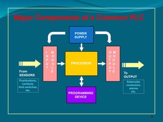
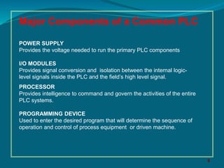
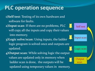
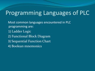
Presented By
SHOBHIT
B.Tech (ECE) 4th yr
MDU University
(Programmable Logic
Controller)
MDU University
Contents
What is PLC?
History of PLC
Major components of PLC
Operational sequence of PLC
Ladder logic
Example of starting and stopping of a motor
Advantages
Disadvantages
Application
What is PLC?
PLC is a digital computer designed for
multiple inputs and output
arrangements, extended temperature
ranges, immunity to electrical noise, and
resistance to vibration and impact. A
PLC is an example of a real time system.
PLC was introduced in late 1960’s
First commercial & successful Programmable Logic
Controllers was designed and developed by Modicon as a
relay replacer for General Motors.
Earlier, it was a machine with thousands of electronic parts.
Later ,in late 1970’s,the microprocessor became reality &
greatly enhanced the role of PLC permitting it to evolve form
simply relay to the sophisticated system as it is today.
5
Major Components of a Common PLC
PROCESSOR
POWER
SUPPLY
I M
N O
P D
U U
T L
E
O M
U O
T D
P U
U L
T E
PROGRAMMING
DEVICE
From
SENSORS
Pushbuttons,
contacts,
limit switches,
etc.
To
OUTPUT
Solenoids,
contactors,
alarms
etc.
6
Major Components of a Common PLC
POWER SUPPLY
Provides the voltage needed to run the primary PLC components
I/O MODULES
Provides signal conversion and isolation between the internal logic-
level signals inside the PLC and the field’s high level signal.
PROCESSOR
Provides intelligence to command and govern the activities of the entire
PLC systems.
PROGRAMMING DEVICE
Used to enter the desired program that will determine the sequence of
operation and control of process equipment or driven machine.
PLC operation sequence
1)Self test: Testing of its own hardware and
software for faults.
2)Input scan: If there are no problems, PLC
will copy all the inputs and copy their values
into memory.
3)Logic solve/scan: Using inputs, the ladder
logic program is solved once and outputs are
updated.
4)Output scan: While solving logic the output
values are updated only in memory when
ladder scan is done, the outputs will be
updated using temporary values in memory.
Self test
Input scan
Logic scan
Output
scan
Programming Languages of PLC
Most common languages encountered in PLC
programming are:
1) Ladder Logic
2) Functional Block Diagram
3) Sequential Function Chart
4) Boolean mnemonics
Plc ppt filke
Plc ppt filke
Plc ppt filke
Plc ppt filke
Plc ppt filke
Plc ppt filke
Plc ppt filke
Plc ppt filke
Plc ppt filke
Plc ppt filke
Plc ppt filke
Plc ppt filke
Plc ppt filke

Plc ppt filke

  • 1.
    Presented By SHOBHIT B.Tech (ECE)4th yr MDU University (Programmable Logic Controller) MDU University
  • 2.
    Contents What is PLC? Historyof PLC Major components of PLC Operational sequence of PLC Ladder logic Example of starting and stopping of a motor Advantages Disadvantages Application
  • 3.
    What is PLC? PLCis a digital computer designed for multiple inputs and output arrangements, extended temperature ranges, immunity to electrical noise, and resistance to vibration and impact. A PLC is an example of a real time system.
  • 4.
    PLC was introducedin late 1960’s First commercial & successful Programmable Logic Controllers was designed and developed by Modicon as a relay replacer for General Motors. Earlier, it was a machine with thousands of electronic parts. Later ,in late 1970’s,the microprocessor became reality & greatly enhanced the role of PLC permitting it to evolve form simply relay to the sophisticated system as it is today.
  • 5.
    5 Major Components ofa Common PLC PROCESSOR POWER SUPPLY I M N O P D U U T L E O M U O T D P U U L T E PROGRAMMING DEVICE From SENSORS Pushbuttons, contacts, limit switches, etc. To OUTPUT Solenoids, contactors, alarms etc.
  • 6.
    6 Major Components ofa Common PLC POWER SUPPLY Provides the voltage needed to run the primary PLC components I/O MODULES Provides signal conversion and isolation between the internal logic- level signals inside the PLC and the field’s high level signal. PROCESSOR Provides intelligence to command and govern the activities of the entire PLC systems. PROGRAMMING DEVICE Used to enter the desired program that will determine the sequence of operation and control of process equipment or driven machine.
  • 7.
    PLC operation sequence 1)Selftest: Testing of its own hardware and software for faults. 2)Input scan: If there are no problems, PLC will copy all the inputs and copy their values into memory. 3)Logic solve/scan: Using inputs, the ladder logic program is solved once and outputs are updated. 4)Output scan: While solving logic the output values are updated only in memory when ladder scan is done, the outputs will be updated using temporary values in memory. Self test Input scan Logic scan Output scan
  • 8.
    Programming Languages ofPLC Most common languages encountered in PLC programming are: 1) Ladder Logic 2) Functional Block Diagram 3) Sequential Function Chart 4) Boolean mnemonics