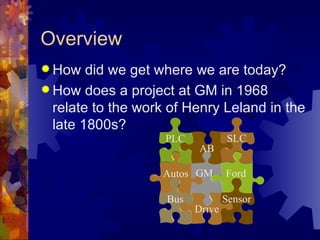
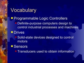
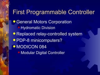
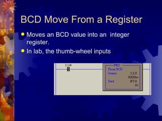
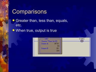
Basics of PLC Programming

   EE 100 – Intro to EE
   Fall 2004
   Dr. Stephen Williams, P.E.
Overview
 How   did we get where we are today?
 How does a project at GM in 1968
  relate to the work of Henry Leland in the
  late 1800s?
                    PLC           SLC
                          AB

                   Autos GM       Ford

                    Bus           Sensor
                          Drive
Vocabulary
 Programmable       Logic Controllers
   Definite-purpose  computers design to
   control industrial processes and machines
 Drives
   Solid-state   devices designed to control
   motors
 Sensors
   Transducers    used to obtain information
First Programmable Controller
 General   Motors Corporation
   Hydromatic   Division
 Replacedrelay-controlled system
 PDP-8 minicomputers?
 MODICON 084
   Modular   Digital Controller
Information Flow
Genesis of Automation
 Operation       sheets
   May   date back to the 1830s
 Listing   of:
   All
      machining operations
   The machine tools employed

   Tools, jigs, fixtures, and gauges

 Organization      and flow of work
Industrial Revolution
 High-volume  production
 Interchangeable parts
 Transportation system
 Inexpensive energy (coal)
 Frederick W. Taylor
   Scientific   management
 Henry   Ford
Purpose of Automation
 Increase productivity
 Standardize
  components or
  processes
 Free workers from
  repetitive, and
  sometime
  dangerous, tasks
Early Automation Applications
   1869 – Refineries in
    Pennsylvania
    automatically covert
    crude oil to kerosene
   1937 – Pictured is the
    loading and unloading
    of stators via an
    overhead conveyor for
    dipping in continuous
    process oven
The Case Against Automation
   Las Vegas Sun, August 2, 1961
       Jimmy Hoffa saw a new industrial revolution
        forming with automation being a threat to his giant
        union more menacing than the Justice
        Department, Attorney General Bobby Kennedy
        and the president himself.
       He felt he could cope with the Senate committees,
        the FBI, and all the new legislation being written,
        which he thinks is aimed at unionism. It is with
        automation that all his talents, energy and ability
        must be directed.
Forces Driving Automation
 Lower  costs
 Faster production
 Better quality control
 How have they remained relevant
  today?
Engineering Resources
   Why do you need all
    of these engineers
    running around to
    make all of this stuff
    work?
Breakthroughs and Plateaus
 Where have we seen breakthroughs,
 and then plateaus of technology?
   Microprocessors

   Graphical User Interfaces
   Power Electronics

   Software Systems
Brief Review of Technology
 Traditional   (ancient?) devices
   Still used in many plants
   If it ain’t broke …

 Where     are we going?
Traditional Relay Logic
 Used  since …
 Control via a series of relay contacts
 On and off inputs
 Race conditions on the outputs
 Very expensive
   Hard  to design and construct
   Difficult to maintain
Traditional Devices
 Relays
 Contactors
 Motor  Starters
 Manually operated switches
 Mechanically operated switches
 Electrically operated switches
Relays
 Original
         control elements
 Now used as auxiliary devices
   The PLC is not designed to switch high
    currents or voltages

                         CR1-1

          CR1
Contactors
 Used  for heavy-duty switching
 Provides isolation from high voltages
  and large currents
 Usefully for large inductive currents,
  such as motor starting
Motor Starters
 Contactors + Overload Relay
 Overload relays were usually heaters
  and bimetal strips
   The   bimetal strip separates when heated
 Next   steps:
   PLCs    and motor starters
   Electronic overloads
   Intelligent starters
Manually Operated Switches
 Pushbuttons
   Normally open
   Normally closed

   Break-then-make

   Make-then-break

 Selector   switches
   Maintained   or spring return
Mechanically Operated
Switches
 LimitSwitches
 Temperature Switches
 Pressure Switches
 Level Switches
Electrically Operated Switches
 PhotoelectricSwitches
 Proximity Switches
What's ahead?
 Solid state devices to replace motor
  starters
 Distributed smart sensors
 Micro- and nanomachines
 Adaptive control
 Smart maintenance
Summary
A  very brief history of industrial
  automation
 Overview of some of the older
  technologies
 Some thoughts on the future
PLC Systems
   CPU
       Processor
       Memory
            One Module
       Power Supply
            Part of the chassis or
             a separate module
 Programming/
  Monitoring Device
 I/0 Modules
Small Logic Controllers
Input and Output
 Input   Modules
   Convert     “real world” signal to PLC input
        24 V, 120 V, Analog, etc.
 Output    Modules
   Convert     PLC signal to “real world” output
        24 V, 120 V, Analog, etc.
 Limiting    values
   PLC    power supply
Configurations
 Fixed   I/O
   Limited   expandability
 Rack
   Many  modules, with the possibility of
    chaining many racks together
 SLC 500 is a fixed I/O device
 SLC 5/02 uses a rack configuration
Chassis Versus Rack
 One “Rack” is 128
  inputs/outputs
 A chassis is the outer
  shell of the PLC
 Chassis ≠ Rack
 SLC 5/02’s in S-340
  have a ten-slot chassis
       Slots are numbered from
        0 to 9
SLC Image Tables
 Hex numbering
 Addressing
   I1:2.0/01
  I  is for the file type
   1 is the file number
   2 is the element number
   .0 is the sub-element number (>16)
   /01 is the bit number
“Real World” Address
 I1:3.0/01
  I  is the module type
   1 is redundant

   3 is the slot number

   .0 is for terminals above 15

   /01 is the terminal number
Remote Racks
 I/O racks located close to the equipment
  being monitored
 Simplifies wiring
 Communication modules
       Similar to LAN
       Fiber Optic
       Coaxial cable
Discrete I/O Modules
 Either  “on” or “off”
 Bit oriented
 Various ratings
   24 V
   120 V

   TTL

   4 – 20 mA
Special I/O Modules
 Analog
 High speed counter
 Thumb-wheel
 TTL
 Encoder
 PID
 Servo
Memory Organization
 Not   the same on all manufactures
   Allen   Bradley uses two main types
 Memory     Maps
   Data  table
   User program
   Internal registers

 Memory     allocation could be fixed or
 variable
SLC Program File Structure
Program File
               Use
Number
0              System Functions

1              Reserved

2              Main Program

3-255          Subroutines
RSLogix 500 Screen
   Define controller
    attributes
       Model
       Memory
       Communication
   Program files
       Main program
       Subprograms
SLC Data File Structure
Data File
            Use
Number
0           Output Image Table

1           Input Image Table

2           Status Table

3           Bit Table
SLC Data File Structure
Data File
            Use
Number
4           Timer Table

5           Counter Table

6           Control Table

7           Integer Table
SLC Data File Structure
Data File
            Use
Number
8           Reserved
            (Floating Point Value Table)
9           Network Table

10-255      Any combination of Bit, Timer,
            Counter, Control, or Integer
            Tables
RSLogix 500 Screen
 Access to
  input and
  output tables
 Access to
  timer and
  control control
  files
Address Format
 What   type of device or module
 Where is it located physically or in
  memory
 For example, T4:0/DN is the done bit for
  timer 0 in file 4
 I:2.0 is an input module in slot 2
 Word versus bit addresses
   I:3.0   is a word, I:3.0/04 is a bit
Multiword Elements
 Timers,counters, and control elements
 Three words used
   Control word to store status
   Preset word to store desired value

   Accumulated word to store present value

   Control file store a length and position
    value (on functions other than counters
    and timers)
Counter Element Example
Name           Address    Example

Control Word   C5:0       C5:0/DN

Preset Word    C5:0.PRE   5000

Accumulated    C5:0.ACC   1240
Word
RSLogix 500 Screen
   Counter C5:0
Program Scan
 Each cycle through
  the program and I/
  O process is called
  a scan
 Scan times vary
  with the length of
  the program and
  the speed of the
  processor
Programming Environments
 Languages   available
   Ladder logic
   Boolean

   Function chart

 Ladder logic is the most common
 Function chart is the future
 C, BASIC, etc., are also possible
Transducers
 Converts    energy from one form to
  another
 Input transducers
   Real   world into the PLC
 Output   transducers
   PLC    to real world
Sensors
 Sensors   are transducers used to
  measure or detect
 Convert mechanical, magnetic, thermal,
  or optical variations into electrical
  quantities
 Sensor input is the basis for most of the
  decisions made in a large system
Proximity Sensors
 Detect the presence of a object (target)
  without physically touching the object
 Solid-state devices
 Completely encapsulated
 Used when:
   Detectingsmall objects
   Rapid response is required
Inductive Proximity Sensors
 Senses  a metallic object
 A change in the magnetic field occurs
  when a metallic object enters into range
 This type of sensor can “see” through
  cardboard boxes and other enclosures
 Current-sourcing or current-sinking
  output
Manually Operated Switches
 Pushbuttons
   Normally open
   Normally closed

   Break-then-make

   Make-then-break

 Selector   switches
   Maintained   or spring return
Counter Instructions
 Count  Up or Down
 Similar to timers, but without an internal
  source
 Two methods used: block and coil
   SLC   5/02s use the coil format
 PREset and ACCumlated values
 RESet similar to RTO
How Counters Work
 Increment   or decrement on a false to
  true input transition
 They are retentive
   The accumulated value remains when the
    rung goes false
 PREsetcan be changed by the
 program
   Move   a new value into C5:0.PRE
Control Bits
15     14    13    12     11      10

CU     CD    DN    OV     UN      UA

 CU = Count Up
 CD = Count Down
 DN = Done
 OV = Overflow, UN = Underflow
Integer Limits
 PREset  and ACCumulator values must
  be integers
 Integers on the SLC 5/02 range from
  32,767 to -32,768
 Cascade counters to go beyond these
  limits
Cascading Example
Down Counters
 The
    SLC 5/02 does not have a true
 down counter
   The counter does not start at a value and
   become true when the ACCumulator is
   zero
 TheSLC 5/02 CTD works with another
 counter with the same address
Down Counter Example
Types of Data Instructions
 Math   Functions
   Add,   subtract, multiply, etc.
 Data   Conversion and Comparison
   Integer   to BCD, Less than, Equal, etc.
 Logical   Operations
Bits, Words, and Files
A   bit is the smallest unit of information
  T4:0/DN     is a bit
A   “word” is another name for a register
  T4:0.PRE         is a word
A “file” is a block of words, also known
 as a table
  T4   is a file
Data Transfer – Move
   The move instruction takes a
    value from a register, or a
    constant value, and places it
    in another register
BCD Move Into a Register
 Moves an integer value into a BCD
  device.
 In lab, the LED Display
BCD Move From a Register
 Moves an BCD value into an integer
  register.
 In lab, the thumb-wheel inputs
Comparisons
 Greater than, less than, equals,
  etc.
 When true, output is true
Today’s Task
 Use what you have
  learned to “break
  the code”
 Each bench has a
  PLC program
 The first bench to
  turn on all five lamps
  wins!

Programmable logic controllers

  • 1.
    Basics of PLCProgramming EE 100 – Intro to EE Fall 2004 Dr. Stephen Williams, P.E.
  • 2.
    Overview  How did we get where we are today?  How does a project at GM in 1968 relate to the work of Henry Leland in the late 1800s? PLC SLC AB Autos GM Ford Bus Sensor Drive
  • 3.
    Vocabulary  Programmable Logic Controllers  Definite-purpose computers design to control industrial processes and machines  Drives  Solid-state devices designed to control motors  Sensors  Transducers used to obtain information
  • 4.
    First Programmable Controller General Motors Corporation  Hydromatic Division  Replacedrelay-controlled system  PDP-8 minicomputers?  MODICON 084  Modular Digital Controller
  • 5.
  • 6.
    Genesis of Automation Operation sheets  May date back to the 1830s  Listing of:  All machining operations  The machine tools employed  Tools, jigs, fixtures, and gauges  Organization and flow of work
  • 7.
    Industrial Revolution  High-volume production  Interchangeable parts  Transportation system  Inexpensive energy (coal)  Frederick W. Taylor  Scientific management  Henry Ford
  • 8.
    Purpose of Automation Increase productivity  Standardize components or processes  Free workers from repetitive, and sometime dangerous, tasks
  • 9.
    Early Automation Applications  1869 – Refineries in Pennsylvania automatically covert crude oil to kerosene  1937 – Pictured is the loading and unloading of stators via an overhead conveyor for dipping in continuous process oven
  • 10.
    The Case AgainstAutomation  Las Vegas Sun, August 2, 1961  Jimmy Hoffa saw a new industrial revolution forming with automation being a threat to his giant union more menacing than the Justice Department, Attorney General Bobby Kennedy and the president himself.  He felt he could cope with the Senate committees, the FBI, and all the new legislation being written, which he thinks is aimed at unionism. It is with automation that all his talents, energy and ability must be directed.
  • 11.
    Forces Driving Automation Lower costs  Faster production  Better quality control  How have they remained relevant today?
  • 12.
    Engineering Resources  Why do you need all of these engineers running around to make all of this stuff work?
  • 13.
    Breakthroughs and Plateaus Where have we seen breakthroughs, and then plateaus of technology?  Microprocessors  Graphical User Interfaces  Power Electronics  Software Systems
  • 14.
    Brief Review ofTechnology  Traditional (ancient?) devices  Still used in many plants  If it ain’t broke …  Where are we going?
  • 15.
    Traditional Relay Logic Used since …  Control via a series of relay contacts  On and off inputs  Race conditions on the outputs  Very expensive  Hard to design and construct  Difficult to maintain
  • 16.
    Traditional Devices  Relays Contactors  Motor Starters  Manually operated switches  Mechanically operated switches  Electrically operated switches
  • 17.
    Relays  Original control elements  Now used as auxiliary devices  The PLC is not designed to switch high currents or voltages CR1-1 CR1
  • 18.
    Contactors  Used for heavy-duty switching  Provides isolation from high voltages and large currents  Usefully for large inductive currents, such as motor starting
  • 19.
    Motor Starters  Contactors+ Overload Relay  Overload relays were usually heaters and bimetal strips  The bimetal strip separates when heated  Next steps:  PLCs and motor starters  Electronic overloads  Intelligent starters
  • 20.
    Manually Operated Switches Pushbuttons  Normally open  Normally closed  Break-then-make  Make-then-break  Selector switches  Maintained or spring return
  • 21.
    Mechanically Operated Switches  LimitSwitches Temperature Switches  Pressure Switches  Level Switches
  • 22.
    Electrically Operated Switches PhotoelectricSwitches  Proximity Switches
  • 23.
    What's ahead?  Solidstate devices to replace motor starters  Distributed smart sensors  Micro- and nanomachines  Adaptive control  Smart maintenance
  • 24.
    Summary A verybrief history of industrial automation  Overview of some of the older technologies  Some thoughts on the future
  • 25.
    PLC Systems  CPU  Processor  Memory  One Module  Power Supply  Part of the chassis or a separate module  Programming/ Monitoring Device  I/0 Modules
  • 26.
  • 27.
    Input and Output Input Modules  Convert “real world” signal to PLC input  24 V, 120 V, Analog, etc.  Output Modules  Convert PLC signal to “real world” output  24 V, 120 V, Analog, etc.  Limiting values  PLC power supply
  • 28.
    Configurations  Fixed I/O  Limited expandability  Rack  Many modules, with the possibility of chaining many racks together  SLC 500 is a fixed I/O device  SLC 5/02 uses a rack configuration
  • 29.
    Chassis Versus Rack One “Rack” is 128 inputs/outputs  A chassis is the outer shell of the PLC  Chassis ≠ Rack  SLC 5/02’s in S-340 have a ten-slot chassis  Slots are numbered from 0 to 9
  • 30.
    SLC Image Tables Hex numbering  Addressing  I1:2.0/01 I is for the file type  1 is the file number  2 is the element number  .0 is the sub-element number (>16)  /01 is the bit number
  • 31.
    “Real World” Address I1:3.0/01 I is the module type  1 is redundant  3 is the slot number  .0 is for terminals above 15  /01 is the terminal number
  • 32.
    Remote Racks  I/Oracks located close to the equipment being monitored  Simplifies wiring  Communication modules  Similar to LAN  Fiber Optic  Coaxial cable
  • 33.
    Discrete I/O Modules Either “on” or “off”  Bit oriented  Various ratings  24 V  120 V  TTL  4 – 20 mA
  • 34.
    Special I/O Modules Analog  High speed counter  Thumb-wheel  TTL  Encoder  PID  Servo
  • 35.
    Memory Organization  Not the same on all manufactures  Allen Bradley uses two main types  Memory Maps  Data table  User program  Internal registers  Memory allocation could be fixed or variable
  • 36.
    SLC Program FileStructure Program File Use Number 0 System Functions 1 Reserved 2 Main Program 3-255 Subroutines
  • 37.
    RSLogix 500 Screen  Define controller attributes  Model  Memory  Communication  Program files  Main program  Subprograms
  • 38.
    SLC Data FileStructure Data File Use Number 0 Output Image Table 1 Input Image Table 2 Status Table 3 Bit Table
  • 39.
    SLC Data FileStructure Data File Use Number 4 Timer Table 5 Counter Table 6 Control Table 7 Integer Table
  • 40.
    SLC Data FileStructure Data File Use Number 8 Reserved (Floating Point Value Table) 9 Network Table 10-255 Any combination of Bit, Timer, Counter, Control, or Integer Tables
  • 41.
    RSLogix 500 Screen Access to input and output tables  Access to timer and control control files
  • 42.
    Address Format  What type of device or module  Where is it located physically or in memory  For example, T4:0/DN is the done bit for timer 0 in file 4  I:2.0 is an input module in slot 2  Word versus bit addresses  I:3.0 is a word, I:3.0/04 is a bit
  • 43.
    Multiword Elements  Timers,counters,and control elements  Three words used  Control word to store status  Preset word to store desired value  Accumulated word to store present value  Control file store a length and position value (on functions other than counters and timers)
  • 44.
    Counter Element Example Name Address Example Control Word C5:0 C5:0/DN Preset Word C5:0.PRE 5000 Accumulated C5:0.ACC 1240 Word
  • 45.
  • 46.
    Program Scan  Eachcycle through the program and I/ O process is called a scan  Scan times vary with the length of the program and the speed of the processor
  • 47.
    Programming Environments  Languages available  Ladder logic  Boolean  Function chart  Ladder logic is the most common  Function chart is the future  C, BASIC, etc., are also possible
  • 48.
    Transducers  Converts energy from one form to another  Input transducers  Real world into the PLC  Output transducers  PLC to real world
  • 49.
    Sensors  Sensors are transducers used to measure or detect  Convert mechanical, magnetic, thermal, or optical variations into electrical quantities  Sensor input is the basis for most of the decisions made in a large system
  • 50.
    Proximity Sensors  Detectthe presence of a object (target) without physically touching the object  Solid-state devices  Completely encapsulated  Used when:  Detectingsmall objects  Rapid response is required
  • 51.
    Inductive Proximity Sensors Senses a metallic object  A change in the magnetic field occurs when a metallic object enters into range  This type of sensor can “see” through cardboard boxes and other enclosures  Current-sourcing or current-sinking output
  • 52.
    Manually Operated Switches Pushbuttons  Normally open  Normally closed  Break-then-make  Make-then-break  Selector switches  Maintained or spring return
  • 53.
    Counter Instructions  Count Up or Down  Similar to timers, but without an internal source  Two methods used: block and coil  SLC 5/02s use the coil format  PREset and ACCumlated values  RESet similar to RTO
  • 54.
    How Counters Work Increment or decrement on a false to true input transition  They are retentive  The accumulated value remains when the rung goes false  PREsetcan be changed by the program  Move a new value into C5:0.PRE
  • 55.
    Control Bits 15 14 13 12 11 10 CU CD DN OV UN UA  CU = Count Up  CD = Count Down  DN = Done  OV = Overflow, UN = Underflow
  • 56.
    Integer Limits  PREset and ACCumulator values must be integers  Integers on the SLC 5/02 range from 32,767 to -32,768  Cascade counters to go beyond these limits
  • 57.
  • 58.
    Down Counters  The SLC 5/02 does not have a true down counter  The counter does not start at a value and become true when the ACCumulator is zero  TheSLC 5/02 CTD works with another counter with the same address
  • 59.
  • 60.
    Types of DataInstructions  Math Functions  Add, subtract, multiply, etc.  Data Conversion and Comparison  Integer to BCD, Less than, Equal, etc.  Logical Operations
  • 61.
    Bits, Words, andFiles A bit is the smallest unit of information  T4:0/DN is a bit A “word” is another name for a register  T4:0.PRE is a word A “file” is a block of words, also known as a table  T4 is a file
  • 62.
    Data Transfer –Move  The move instruction takes a value from a register, or a constant value, and places it in another register
  • 63.
    BCD Move Intoa Register  Moves an integer value into a BCD device.  In lab, the LED Display
  • 64.
    BCD Move Froma Register  Moves an BCD value into an integer register.  In lab, the thumb-wheel inputs
  • 65.
    Comparisons  Greater than,less than, equals, etc.  When true, output is true
  • 66.
    Today’s Task  Usewhat you have learned to “break the code”  Each bench has a PLC program  The first bench to turn on all five lamps wins!

Editor's Notes

  • #8 1895 paper to ASME
  • #11 He told of a new brewery built in Florida with a capacity of 1,300,000 barrels a year. The same-size brewery in Milwaukee turning out the same amount of barrels employed 586 men. The new plant hires 107 men. That's less than one-fifth, which means that 80 percent of brewery labor will go jobless as new plants go into operation.