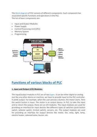
The document provides an overview of programmable logic controllers (PLCs). It discusses that PLCs are digital electronic devices that use programmable memory to implement control functions like logic, sequencing, timing, counting, and arithmetic. The key components of a PLC include input/output modules, a power supply, a central processing unit, memory, and a programming device. PLCs work by continuously scanning programs in a cycle that involves reading inputs, executing the program logic, and updating outputs. This allows PLCs to control machines and processes.
![UNIT-I
INTRODUCTION TO PLC
What is the Programmable Logic Controller
[PLC]?
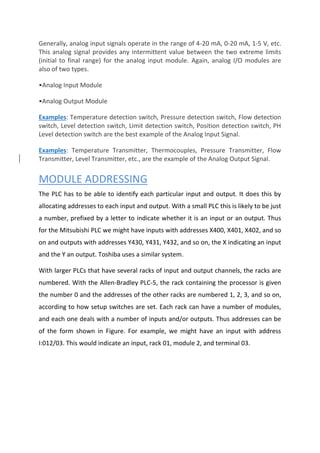
PLC is a solid-state control device or computerized industrial controller that
performs discrete or sequential logic in the factory or automation
environment.
Basically, PLC is a combination of software and hardware. It acts as the brain of the
machine or system for automation control systems.
Technical Definition of PLC:
The digital electronic device that uses programmable memory to store
instructions and implement specific function such as programming logic,
sequence, timing, counting and arithmetic operations to control electronic
machines and technical process.
Schematic figure of the PLC (Compact/Mini PLC)
Building Blocks of PLC](https://image.slidesharecdn.com/plc-converted-230318130111-8e0a3fb7/85/PLC-converted-pdf-1-320.jpg)


![[English Version]Maker-Ray Product Brochure V3 .pdf](https://cdn.slidesharecdn.com/ss_thumbnails/englishversionmaker-rayproductbrochurev3-260113094444-0156dbdc-thumbnail.jpg?width=640&height=640&fit=bounds)


