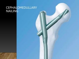
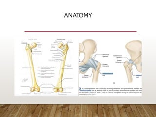
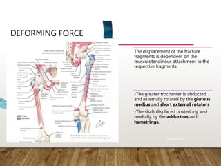
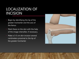
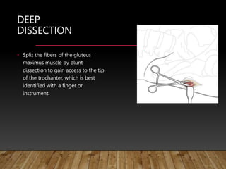
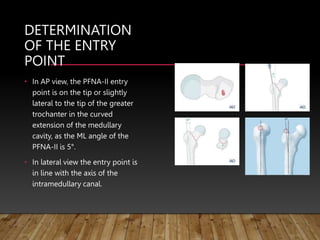
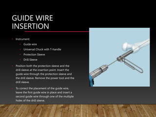
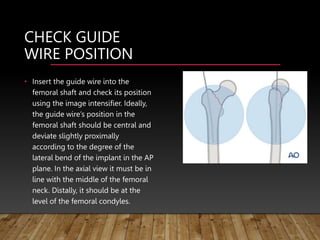
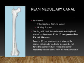
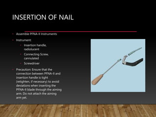
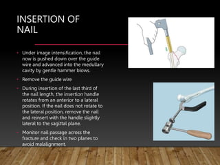
3. MECHANISM OF INJURY
Low-energy falls from a standing
height account for approximately 90% of
community hip fractures in patients over
50 years of age with a higher proportion
of females.
High energy hip fractures are relatively
rare, more common in males under 40
years of age
Rockwood 8th ed
4. DEFORMING FORCE
The displacement of the fracture
fragments is dependent on the
musculotendinous attachment to the
respective fragments.
-The greater trochanter is abducted
and externally rotated by the gluteus
medius and short external rotators
-The shaft displaced posteriorly and
medially by the adductors and
hamstrings.
Rockwood 8th ed
5. SIGN AND
SYMPTOMS
History of pain and inability to
ambulate after a fall or other injury.
The pain is localized to the proximal
thigh and is exacerbated by passive or
active attempts of hip flexion or
rotation.
Physical findings of a displaced hip
fracture are shortening and external
rotation of the extremity
Rockwood 8th ed
6. CLASSIFICATION: BOYD AND GRIFFIN
Type 1: Fractures that extend along the
intertrochanteric line (stable –two part)
Type 2: Comminuted fractures with the main
fracture line along the intertrochanteric line
with posteromedial comminution
Type 3: Subtrochanteric extension with lateral
shaft extension of the fracture distally at or
below the lesser trochanter
Type 4: Subtrochanteric with intertrochanteric
extension with the fracture lying in at least 2
planes
Rockwood 8th ed, Campbell
8. AO CLASSIFICATION
31A1: Fractures are not
comminuted (single fracture line
extending medially).
31A2: Fractures have increasing
comminution (separate lesser
trochanteric fragment).
31A3: Fractures include reverse
obliquity, transverse, or
subtrochanteric extension patterns.
Campbell
9. CONSIDERATION
Fractures where the lesser trochanter is still
attached to the femoral shaft are generally
called stable trochanteric fractures
because after anatomic reduction and
internal fixation there is little tendency to
loss of reduction under physiological
loading.
If the lesser trochanter is attached to the
proximal fragment, closed reduction is
usually impossible because the pull of the
psoas muscle will flex and externally rotate
the proximal fragment, and traction will not
correct this displacement. Therefore, one
usually has to carry out an open reduction. https://www2.aofoundation.or
g/
10. OPERATIVE
TREATMENT
Surgical management once selected
should be performed as soon as any
correctable metabolic, hematologic,
or organ system instability has been
rectified. This is within the first 24
to 48 hours for most patients.
Surgical implant options included
plate and screw constructs, either nail
or screws for the head fixation, nail
constructs with either nail or screws,
external fixation, and arthroplasty.
Rockwood 8th ed
11. • Anatomic reduction Before inserting the
nail, the reduction can be achieved
manually or using a reduction table.
• Stable fixation the intramedullary nail
acts as an internal splint that controls but
does not prevent micromovements of the
fragments. It provides a relative stability
that leads to an indirect healing through
callus formation.
• Preservation of blood supply When the
canal is not reamed, intramedullary nailing
generates minimal trauma to the
endosteum and, therefore, the blood
supply is maximized through the uninjured
endosteum and periosteum. Reaming the
canal temporarily disrupts the endosteal
blood supply but probably stimulates the
revascularization and therefore the bone
healing.
• Early, active mobilization
Intramedullary nailing, combined with the
AO technique, provides relatively stable
fracture fixation with minimal trauma to
vascular supply.
In 1958, the AO formulated four basic principles, which have
become the guidelines for internal fixation in general, and
intramedullary nailing in particular:
12. PFNA VS PFNA-II
• Because of the height in Asian population on
average is less than that of Americans or
Europeans, the femoral neck diameter and
proximal femoral length are relatively shorter.
• The standard proximal femoral nail antirotation
nail has a mediolateral angle of 6° and a
proximal diameter of 17 mm. To insert the nail,
a much larger femoral canal needs to be
prepared to accommodate the nail of the given
diameter. This means that a mass of cortical
bone has to be reamed, thus weakening the
osteoporotic bone in most patients.
• The PFNA-II was designed to have a
mediolateral angle of 5° and a proximal
diameter of 16.5 mm. The modified nail has a
considerably better anatomic fit.
13.
14.
15. PFNA-II BLADE
• Compaction of cancellous bone
• Inserting the PFNA-II blade compacts the
cancellous bone providing additional
anchoring, which is especially important
in osteoporotic bone.
• Large surface and increasing core diameter
for maximum compaction and optimal hold
in bone
• Increased stability caused by bone
compaction around the PFNA-II blade
has been biomechanically proven to
retard rotation and varus collapse.
Biomechanical tests have demonstrated
that the PFNA-II blade had a significantly
higher cut-out resistance in comparison
with commonly-used screw systems.
16. PFNA SHORT (LENGTH
170 MM – 240 MM)
• Indications
• Pertrochanteric fractures (31-
A1 and 31-A2)
• Intertrochanteric fractures (31-
A3)
• High subtrochanteric fractures
(32-A1)
• Contraindications
• Low subtrochanteric fractures
• Femoral shaft fractures
• Isolated or combined medial
femoral neck fractures
17. PFNA LONG (LENGTH
260 MM – 420 MM)
• Indications
• Low and extended
subtrochanteric fractures
• Ipsilateral trochanteric
fractures
• Combination fractures (in the
proximal femur)
• Pathological fractures
• Contraindications
• Isolated or combined medial
femoral neck fractures
19. • Preoperatively check the
degree of the anterior
bow of the femur on an
x-ray of the uninjured
extremity. If the tip of the
nail comes to lie at the
apex of the anterior bow,
use a long nail or choose
a plate.
20. POSITIONING
• The patient is positioned supine on
the fracture table. The ipsilateral
arm is elevated in a sling while the
uninjured leg is placed on a leg
holder. It is important to ensure
that the ipsilateral hip is in an
adducted position.
• To accomplish this, push the torso
10º to 15º to the contralateral side
21. CLOSED
REDUCTION
• To reduce the fracture, first apply
traction in the direction of the length
of the extremity. This will distract the
fragments and regain length.
• The second step is internal rotation.
Check each step with the image
intensifier.
• Excessive traction, in an attempt to
reduce the fracture, can lead to pelvic
rotation around the perineal post of
the fracture table. When the pelvis
rotates, as illustrated, it produces
relative abduction of the hip, thus
interfering with access to the
proximal femoral nail entry site
23. DETERMINATION OF
NAIL LENGTH
• Instrument: Radiographic Ruler for PFNA
• Position the C-arm for an AP view of the
proximal femur. With long forceps, hold the
ruler alongside the lateral thigh, parallel to
and at the same level as the femur. Adjust
the ruler until the proximal end is at the
desired nail insertion position. Mark the skin
at the proximal end of the ruler.
• Move the C-arm distally. Align the proximal
end of the radiographic ruler to the skin
mark, and take an AP image of the distal
part.
24. DETERMINATION OF
NAIL DIAMETER
• Place the radiographic canal width estimator
perpendicular to the femur axis so that the
diameter gauge is located over the isthmus.
• Select the nail diameter with which the
intramedullary canal-to-cortex transition is still
visible on both sides of the diameter gauge.
• Notes
• If the reamed technique is used, the diameter of
the largest medullary reamer applied must be 0.5
mm to 1.5 mm larger than the nail diameter.
• Always choose the largest diameter nail that fits
into the intramedullary canal (9 mm nails should
only be used for an intramedullary canal smaller
than 11 mm).
25. LOCALIZATION OF
INCISION
• Begin by identifying the tip of the
greater trochanter and the axis of
the femur.
• Mark these on the skin with the help
of the image intensifier, if necessary.
• Make a 3-5 cm skin incision several
centimeters proximal to the tip of
the greater trochanter
26. SUPERFICIAL
DISSECTION
• Make a 3-8 cm straight
longitudinal incision in the
fascia of the gluteus muscle,
centered on the skin mark.
27. DEEP
DISSECTION
• Split the fibers of the gluteus
maximus muscle by blunt
dissection to gain access to the tip
of the trochanter, which is best
identified with a finger or
instrument.
28. DETERMINATION
OF THE ENTRY
POINT
• In AP view, the PFNA-II entry
point is on the tip or slightly
lateral to the tip of the greater
trochanter in the curved
extension of the medullary
cavity, as the ML angle of the
PFNA-II is 5°.
• In lateral view the entry point is
in line with the axis of the
intramedullary canal.
29. GUIDE WIRE
INSERTION
• Instrument:
• Guide wire
• Universal Chuck with T-handle
• Protection Sleeve
• Drill Sleeve
• Position both the protection sleeve and the
drill sleeve at the insertion point. Insert the
guide wire through the protection sleeve and
the drill sleeve. Remove the power tool and the
drill sleeve.
• To correct the placement of the guide wire,
leave the first guide wire in place and insert a
second guide wire through one of the multiple
holes of the drill sleeve.
30. CHECK GUIDE
WIRE POSITION
• Insert the guide wire into the
femoral shaft and check its position
using the image intensifier. Ideally,
the guide wire’s position in the
femoral shaft should be central and
deviate slightly proximally
according to the degree of the
lateral bend of the implant in the AP
plane. In the axial view it must be in
line with the middle of the femoral
neck. Distally, it should be at the
level of the femoral condyles.
31. REAMING
• Opening of the femur
• Insert the protection sleeve with its trocar over
the guide wire and push it through the soft tissues
until it abuts against the greater trochanter. Then
withdraw the trocar and insert an appropriate drill
bit over the guide wire. Ream out the trochanteric
area. Ream by hand in the elderly to avoid
damage to the fragile trochanteric shell. In young
patients, use power. Remove the guide wire after
reaming.
• Note
Only in exceptional cases, where the medullary
canal is smaller than the chosen nail, it will be
necessary to over ream the femoral shaft so that
its diameter is 1 mm greater than that of the
chosen nail.
32. OPEN FEMUR
WITH DRILL BIT
• Instrument:
• Drill Bit 17 mm, cannulated
• Protection Sleeve
• Guide the drill bit through the
protection sleeve over the guide
wire and drill as far as the stop on
the protection sleeve. Remove the
drill bit, the protection sleeve and
the guide wire.
33. OPEN FEMUR
(WITH AWL)
• Instrument: Awl
• Guide the awl over the guide wire
and prepare with bi-direc- tional
turns the cavity for the proximal
part of the PFNA-II nail. Remove the
awl and the guide wire.
34. REAM MEDULLARY CANAL
• Instrument:
• Intramedullary Reaming System
• Holding Forceps
• Starting with the 8.5 mm diameter reaming head,
ream to a diameter of 0.5 to 1.5 mm greater than
the nail diameter.
• Ream in 0.5 mm increments and advance the
reamer with steady, moderate pressure. Do not
force the reamer. Partially retract the reamer
repeatedly to clear debris from the medullary canal.
35. REAMING
• Pearl: Maintaining reduction
during reaming
• If the fracture passes through
the nail entry site, a medially
directed force applied to the
lateral trochanteric region
helps prevent drills or
reamers from displacing the
greater trochanteric
segment(s) laterally. This
allows reaming of a channel
for the nail, so that its
insertion does not distract
the fracture.
36. INSERTION OF NAIL
• Assemble PFNA-II Instruments
• Instrument:
• Insertion handle,
radiolucent
• Connecting Screw,
cannulated
• Screwdriver
• Precaution: Ensure that the
connection between PFNA-II and
insertion handle is tight
(retighten, if necessary) to avoid
deviations when inserting the
PFNA-II blade through the aiming
arm. Do not attach the aiming
arm yet.
37. INSERTION OF
NAIL
• Under image intensification, the nail
now is pushed down over the guide
wire and advanced into the medullary
cavity by gentle hammer blows.
• Remove the guide wire
• During insertion of the last third of
the nail length, the insertion handle
rotates from an anterior to a lateral
position. If the nail does not rotate to
the lateral position, remove the nail
and reinsert with the handle slightly
lateral to the sagittal plane.
• Monitor nail passage across the
fracture and check in two planes to
avoid malalignment.
38. PROXIMAL
LOCKING
• Instrument:
• Aiming arm
• Plug for aiming arm
• Mount the appropriate aiming arm
based on the chosen CCD angle of the
PFNA-II and fix it firmly to the
insertion handle.
• Make a small skin incision at the
appropriate place. Insert the drill
sleeve assembly through the aiming
device and advance it through the soft
tissues to the lateral cortex.
39. PREPARE GUIDE
WIRE INSERTION
• Instrument:
• Buttress/Compression Nut
• Protection Sleeve
• Drill Sleeve 11.0/3.2
• Trocar, gold
• Screw the buttress nut on the protection sleeve for
PFNA blade. Make sure the «lateral side» marking
points towards the head of the sleeve. Screw the
buttress nut up to the marking on the protection
sleeve.
• Insert the drill sleeve and the trocar through the
protection sleeve.
• Advance the entire sleeve assembly for PFNA blade
through the aiming arm to the skin until it clicks
into the aiming arm. Adjust the position of the
buttress nut if necessary.
40. POSITION GUIDE WIRE WITH
AIMING DEVICE
• Attach the guide wire aiming device for AP orientation to the aiming arm
using the connecting screw for PFNA.
• Position the C-arm for the AP view. Rotate the C-Arm until any two
orientation lines are symmetric to the protection sleeve.
• The midline in between these two orientation lines predicts the location of
the guide wire and PFNA Blade.
• Adapt the insertion depth of the nail until the midline is centered in the
femoral head.
• Position the C-arm in the true lateral view (alignment of the axis of the
femoral neck congruent with the axis of the femoral shaft).
• Adjust nail rotation until the two lines on the insertion handle are
symmetric to the PFNA nail.
• Note: The outer lines can be used to determine the center of the femoral
head.
41. INSERTING GUIDE
WIRE
• Insert the sleeve assembly as far as
the lateral cortex. Advance the
protection sleeve to the lateral cortex
using slight clockwise turns of the
buttress nut. Prepare the passage of
the protection sleeve by turning the
internal drill sleeve.
• The sleeve assembly must be in
contact with the bone during the
entire blade implantation. Do not
tighten the buttress nut too firmly as
this could impair the precision of the
insertion handle and sleeve assembly.
42. INSERTING GUIDE
WIRE (2)
• In the AP and lateral view, the optimal position
of the guide wire is the exact center of the
femoral head. Insert the guide wire
subchondrally into the femoral head at a
distance of
10 mm below the joint level. Minimal distance
to the joint is 5 mm. The tip of the guide wire is
positioned at the intended blade tip position.
• If the PFNA-II or the guide wire requires
repositioning; remove the guide wire, release
the sleeve assembly with buttress nut from the
aiming arm by pressing the button on the
clamp device, and remove it. The PFNA-II can
be repositioned only by rotation, deeper
insertion or partial retraction. Reinsert the
sleeve assembly and turn the buttress nut
clock-wise to position the assembly on the
bone. Introduce a new guide wire.
43. • The ideal position of the guide
wire in the AP plane is in line
with the axis of the neck and
slightly in the lower half. In the
lateral view it must be in line
with the axis of the neck.
• The guide wire is inserted
subchondrally into the femoral
head. Its tip should end 5 mm
proximal of the joint.
44. Achieve a neck-shaft axis >130°
• Avoiding varus deformity is
important to improve fixation,
and to preserve functionally
important anatomy. Begin by
choosing a nail with a neck-shaft
angle of at least 130°.
• Tips to correct varus:
• Advance nail
• Increase traction
• Remove guide wire from the
femoral head and abduct extremity
45. MEASURE PFNA-II
BLADE LENGTH
• Instrument:
• Direct Measuring Device for Guide Wire
• Verify the position of the guide wire in AP and
lateral view before measuring the length.
• Guide the measuring device over the guide
wire. Advance the measuring device to the
protection sleeve and determine the length of
the required blade. The measuring device
indicates the exact length of the guide wire in
the bone.
• In the AP and lateral view, the correct position
of the PFNA-II blade is 10 mm below the joint
level. Minimal distance to the joint is 5 mm. If
the guide wire’s position is subchondral, sub-
tract 10 mm to measure the PFNA-II blade
length correctly.
46. MEASURING LENGTH OF
BLADE
• Because the tip of the guide
wire was inserted into the
subchondral bone, take a
blade which is 10-15 mm
shorter than the
measurement. This will
ensure that the tip of the
blade will be 10 mm from
the joint.
47. OPEN LATERAL
CORTEX
• Instrument:
• Drill Bit 11 mm
• Push the cannulated drill bit over
the 3.2 mm guide wire. Drill to the
stop. This opens the lateral cortex.
48. DRILL HOLE FOR
PFNA-II BLADE
• Instrument:
• Reamer 11 mm
• Fixation Sleeve
• Set the chosen blade length on the
cannulated reamer by fixing the
fixation sleeve in the corresponding
position. Read off the correct length
on the side of the fixation sleeve
pointing towards the tip of the reamer.
• Push the reamer over the guide wire.
Monitor drilling under image
intensifier control. Drill to the stop.
The fixation sleeve prevents further
drilling.
49. ASSEMBLE PFNA-II BLADE
ON THE IMPACTOR
• Instrument:
• Impactor
• The PFNA-II blade is supplied in a locked state.
• While attaching the PFNA-II blade on the impactor,
screw the impactor counterclockwise (note the mark
“attach” on the impactor) into the end of the PFNA-
II blade to unlock the blade. Push the PFNA-II blade
gently towards the impactor while attaching the
PFNA-II blade. Do not overtighten.
50. INSERT PFNA-II
BLADE
• Instrument:
• Combined Hammer
• Insert the blade-impactor assembly
over the guide wire. Push the button
on the protection sleeve, align the
blade (note marking on the protection
sleeve) and advance the blade
impactor assembly further through the
protection sleeve.
• Use monitoring during insertion of the
PFNA-II blade.
• Insert the PFNA-II blade to the stop by
applying gentle blows with the
hammer.
51. LOCK PFNA-II
BLADE
• To lock the PFNA-II blade, turn the
impactor clockwise (note «lock» marking
on the handle) and tighten the blade.
• Verify PFNA-II blade locking
intraoperatively. The PFNA-II blade is
locked if all gaps are closed.
• Press the button on the protection sleeve
to remove the impactor. Remove and
dispose of the guide wire.
• When proximal locking is complete,
release and remove the protection sleeve
and the buttress nut by pressing the
button on the clamp device of the aiming
arm in order to continue with distal locking
or leave it in place to continue with intra-
operative compression.
52. INTRAOPERATIVE
COMPRESSION
• Instrument:
• Compression Instrument
• Precaution: Do not use intraoperative
compression in osteoporotic bone.
• Screw the compression instrument into the
blade through the protection sleeve.
• Turn the buttress nut counterclockwise to
move the protection sleeve backwards until
it is pushing towards the compression
instrument.
• Under image intensifier control, further turn
the buttress nut counterclockwise to
achieve intraoperative compression and
close the fracture gap
53. DISTAL LOCKING
• Instrument:
• Protection sleeve
• Drill sleeve
• Trocar
• Using the hexagonal screwdriver with
spherical head, confirm that the
connecting screw between the insertion
handle and the PFNA-II is sufficiently
tightened.
• Insert the three-part trocar combination
(protection sleeve, drill sleeve and trocar)
through the hole in the aiming arm that
corresponds with the nail length, make a
stab incision and insert the trocar to the
bone. Mark the femur and remove the
trocar.
54. DRILL
• Use the drill bit to drill through both cortices. The
tip of the drill bit should protrude by 2 to 4 mm.
Just after drilling both cortices, confirm the drill bit
position.
• Ensure that the drill sleeve is pressed firmly to the
near cortex and read the measurement from the
calibrated drill bit at
the back of the drill sleeve. This measurement
corresponds to the appropriate length of the
locking bolt. Remove the drill bit and the drill
sleeve.
55. DETERMINE LENGTH
AND INSERT LOCKING
BOLT
• Instrument:
• Measuring device
• Screwdriver
• Insert the depth gauge through the protection
sleeve to the near cortex and advance the hook
through both cortices. Draw back the hook until
it engages in the opposite cortex. Read the
measurement from the depth gauge. Add 2 to 4
mm to the measured length to ensure good
engagement of the locking bolt in the opposite
cortex.
• Insert a locking bolt of the measured length
with the hexagonal screwdriver through the
protection sleeve until the locking bolt head lies
against the near cortex. The tip of the locking
bolt should not project more than 1–2 mm
beyond the far cortex.
56. DISTAL LOCKING
• Drilling hole for distal locking
• Make a stab incision and insert the
drill bit using a protection sleeve
through the selected locking hole.
Drill both cortices.
• Insertion of locking bolt
• For simple and multifragmentary
pertrochanteric fractures static
locking is sufficient. This should be
inserted according to the producer’s
instructions.
57. • Insertion of end cap
Use of an end cap might be considered,
according to producer's instructions.
However, as nearly none of the implants
will be removed, this step is generally
not necessary. The final position of the
nail is checked in two planes.
58. POSTOPERAT
IVE
TREATMENT
• Intramedullary fixation of these fractures allows for immediate postoperative full weight bearing rehabilitation.
• Follow-up
• Follow up visits at six-week intervals with x-rays should be carried out until union and thereafter as necessary.
• Implant removal
• Implant removal is not necessary unless clinically indicated.
• Mortality
Mortality generally occurs within the first six months after fracture; studies have shown that these rates range
from 12-37%.
Predictors of higher mortality rates are patients who are:
• older
• male
• have other comorbid conditions (such as cardiac failure, diabetes, and chronic air flow limitation)
• have cognitive disorders.