SlideShare a Scribd company logo
Dr. Ramesh B T
Assistant Professor
Mechanical Engg. Dept.
JIT-Davanagere
Email Id: rameshbt049@gmail.com
26-06-2021
Dr. Ramesh B T 1
Performance Analysis on Liquid flat plate
collectors
26-06-2021
Dr. Ramesh B T 2
26-06-2021
Dr. Ramesh B T 3
26-06-2021
Dr. Ramesh B T 4
26-06-2021
Dr. Ramesh B T 5
26-06-2021
Dr. Ramesh B T 6
26-06-2021
Dr. Ramesh B T 7
26-06-2021
Dr. Ramesh B T 8
26-06-2021
Dr. Ramesh B T 9
26-06-2021
Dr. Ramesh B T 10
• Effect of Shading
• Collect Tilt
• Fluid Inlet Temperature
• Dust on the top Cover
26-06-2021
Dr. Ramesh B T 11
26-06-2021
Dr. Ramesh B T 12
Stagnation temperature
Stagnation temperature is the temperature reached when stagnation persists until the losses of the solar
thermal collectors equal the absorbed energy. The stagnation temperature depends on the ambient
conditions (ambient temperature and hemispherical irradiance) and reaches different values depending
on these conditions. The standard stagnation temperature defined by the international standard EN ISO
9806:2013 /1/ give the value for the stagnation temperature at 1000 W/m² hemispherical irradiance and
30 °C ambient temperature. This standard stagnation temperature is usually used to describe the highest
temperature reached by the solar thermal collectors
Stagnation describes the state of a solar thermal system in which (by any reason) the flow in the
collector loop is interrupted although sufficient solar irradiance is available for operation of the collector
loop. If stagnation persists and solar irradiance is still being absorbed by the collector, temperatures and
pressure in the collector loop will increase. When the temperature raises higher than the operation
temperature, two things can happen: -
The design temperature is reached: The solar thermal collectors or parts of the collector loop reach a
temperature where (parts of) the collectors (or the collector loop) are damaged. Obviously, this has to
be avoided using appropriate measures.
If the first does not apply and the stagnation persists, the collectors reach their specific maximum
absorber temperature (= stagnation temperature). This temperature depends on the collector design and
the current weather conditions (mainly irradiance and ambient temperature) and the heat transfer
medium conditions inside the collector and/or collector loop.
26-06-2021
Dr. Ramesh B T 13
Transmissivity of the Cover System
26-06-2021
Dr. Ramesh B T 14
26-06-2021
Dr. Ramesh B T 15
26-06-2021
Dr. Ramesh B T 16
26-06-2021
Dr. Ramesh B T 17
26-06-2021
Dr. Ramesh B T 18
26-06-2021
Dr. Ramesh B T 19
The calculation is done in detail for one angle of incidence, viz. θ1=15◦.
Hence, θ2 =sin−1[(sin15◦)/1.52]=9.80◦
ρI =sin2(9.80◦−15◦) sin2(9.80◦+15◦) =0.047
τrI =1−0.047 1+(3×0.047)=0.835
ρII =tan2(9.80◦−15◦) tan2(9.80◦+15◦)=0.039
τrII =1−0.039 1+(3×0.039)=0.860
τr =1/2(0.835+0.860) =0.848
26-06-2021
Dr. Ramesh B T 20
τd =0.885, τr = 0.848
τ =0.848×0.885
τ =0.750
26-06-2021
Dr. Ramesh B T 21
Transmissivity-absorptivity product
The Transmissivity -absorptivity product is defined as the ratio of the flux absorbed in the absorber
plate to the flux incident on the cover system, and is denoted by the symbol (τα), an appropriate
subscript(b or d )being added to indicate the type of incident radiation. An expression for the
Transmissivity absorptivity product will now be derived.
26-06-2021
Dr. Ramesh B T 22
The symbol ρd represents the diffuse reflectivity of the cover system. It can be found by determining the
value τa (1−τr) for the cover system for an incidence angle of 60◦. From Example it is seen that ρd = 0.21 for
a two glass cover system. Similarly, for a one-glass cover system, the value of ρd can be shown to be 0.15.
Over all loss coefficient and heat transfer correlations
Where, Ul = Over all loss coefficient.
Ap = Area of the absorber plate.
Tpm = Average temperature of the absorber plate.
Ta = Average temperature of the absorber plate.
26-06-2021
Dr. Ramesh B T 23
The heat lost from the collector is the sum of the heat lost from the top, the bottom and the sides.
Thus,
Where,
qt = Rate At which heat is lost from the top.
qb = Rate at which heat is lost from the bottom.
qs = Rate at which heat Is lost from the sides.
It will be noted that the definition of each of the coefficients is based on the area Ap and the
temperature difference (Tpm−Ta). This is done for convenience and helps in giving the simple
additive equation
26-06-2021
Dr. Ramesh B T 24
The losses can also be shown in terms of thermal resistances as shown in Fig. The overall loss
coefficient is an important parameter since it is a measure of all the losses. Typical values range
from 2 to10 W/m2-K.
26-06-2021
Dr. Ramesh B T 25
Top loss coefficient
26-06-2021
Dr. Ramesh B T 26
Heat transfer coefficient between inclined parallel surfaces
Heat transfer coefficient at the top cover
26-06-2021
Dr. Ramesh B T 27
Empirical equation for top loss coefficient
26-06-2021
Dr. Ramesh B T 28
Bottom loss coefficient
Side loss coefficient
26-06-2021
Dr. Ramesh B T 29
26-06-2021
Dr. Ramesh B T 30
i)From equation, sky temperature is calculated,
Tsky =Ta−6=297.2−6=291.2 K
ii)Using equation, we can calculate hw,
hw =8.55+2.56V∞ =8.55+(2.56×2.5)=14.95 W/m2−K
iii)Top loss coefficient can be found using empirical equation
Where we need to find values of f and C first,
f = (9/ hw −30/ hw2) (Ta /316.9)(1+0.091M)
26-06-2021
Dr. Ramesh B T 31
26-06-2021
Dr. Ramesh B T 32
v) Side loss co-efficinet can be found using equation
Us =(L1 +L2)L3Ki /(2L1L2δs)
=(0.90×1.90)×(0.4+0.4+0.8)×0.05/0.90×1.90×0.04
Us = 0.33 W/m2−K
26-06-2021
Dr. Ramesh B T 33
Temperature Distribution between the Tubes
it is desirable to have an understanding of the temperature distribution that exists in a solar collector
constructed as shown in below Figure shows a region between two tubes. Some of the solar energy absorbed by
the plate must be conducted along the plate to the region of the tubes, thus the temperature midway between
the tubes will be higher than tube temperature in the . vicinity of the tubes. The temperature above the tubes
will be nearly uniform because of the presence of the tube and weld metal.
The energy transferred to the fluid will heat the fluid, causing a temperature gradient to exist in the direction
of flow. Since in any region of the collector the general temperature level is governed by the local temperature
level of the fluid, a situation as shown in Figure is expected At any location y, the general temperature
distribution in the x direction is as shown in Figure and at any location x, the temperature distribution in the y
direction will look like Figure.
26-06-2021
Dr. Ramesh B T 34
To model the situation shown in Figure , a number of simplifying assumptions can be made to lay the
foundations without obscuring the basic physical situation. These assumptions are as follows: _
1. Performance is steady state.
2. Construction is of sheet and parallel tube type.
3. The headers cover a small area of collector and can be neglected.
4. The headers provide uniform flow to tubes.
5. There is no absorption of solar energy by a cover insofar as it affects losses from the collector.
6. Heat flow through a cover is one dimensional.
7. There is a negligible temperature drop through a cover.
8. The covers are opaque to infrared radiation.
9. There is one-dimensional heat flow through back insulation.
10.The sky can be considered as a blackbody for long-wavelength radiation at an equivalent sky
temperature. .
11.Temperature gradients around tubes can be neglected.
12.The temperature gradients in the direction of flow and between the tubes can be., -- treated-
independently.
13.Properties are independent of temperature.
14.Loss through front and back are to the same ambient temperature.
15. Dust and dirt on the collector are negligible.
16. Shading of the collector absorber plate is negligible
26-06-2021
Dr. Ramesh B T 35
Collector efficiency factor
26-06-2021
Dr. Ramesh B T 36
26-06-2021
Dr. Ramesh B T 37
26-06-2021
Dr. Ramesh B T 38
Next we consider the flow of heat from the plate to the fluid. The three thermal resistances
in the path are due to the adhesive used for attaching the tubes to the absorber plate, the
tube wall and the heat transfer coefficient at the inner surface of the tube. Assuming the
thermal resistance of the tube wall to be negligible.
26-06-2021
Dr. Ramesh B T 39
Where, F0 represents the ratio of the actual useful gain rate per tube per unit
length to the gain which would occur, if the collector absorber plate where at the
temperature Tf
26-06-2021
Dr. Ramesh B T 40
Collector heat removal factor
26-06-2021
Dr. Ramesh B T 41
The term FR is called the collector heat-removal factor. It is an important design
parameter since it is a measure of the thermal resistance encountered by the
absorbed solar radiation in reaching the collector fluid. From above Eq, it can be seen
that FR represents the ratio of the actual useful heat gain rate to the
gainwhichwouldoccurifthecollectorabsorberplatewasatthetemperature Tf i every
where. As such its value ranges between 0 and 1.
26-06-2021
Dr. Ramesh B T 42
26-06-2021
Dr. Ramesh B T 43
ii)Solar hour angle ωs =0,
(at mean of11:30and12:30),
iii)Solar altitude angle αa is given by,
sinαa =cosφcosδcosωs +sinφsinδ
=cos22◦cos(−23◦)cos0◦+sin22◦sin(−23◦)
=0.85−0.146 =0.7036 αa =44.7◦ ...(Ans.)
iv)Incident angle θ,
θ = π 2 −αa =90−44.7◦
θ =45.3◦ ...(Ans.)
26-06-2021
Dr. Ramesh B T 44
26-06-2021
Dr. Ramesh B T 45
viii)Now,
S =HbRb(τα) =350×1.40×0.811 S
=395 W/m2
=340.62 kcal/hr m2
26-06-2021
Dr. Ramesh B T 46
Effect of various parameters on collector performance
a)Heat transfer system
b)Selective surface
c)Number of covers
d)Collector tilt
e)Spacing
f)Fluid temperature
g)Cover transmissivity
h)Dust on top of the cover
i)Performance over a day
26-06-2021
Dr. Ramesh B T 47
Photovoltaic Cell
Definition: The Photovoltaic cell is the semiconductor device that converts the light into electrical energy.
The voltage induces by the PV cell depends on the intensity of light incident on it. The name Photovoltaic is
because of their voltage producing capability.
The energises electron is known as the Photoelectrons. And the phenomenon of emission of electrons
is known as the photoelectric effect. The working of the Photovoltaic cell depends on the photoelectric
effect
26-06-2021
Dr. Ramesh B T 48
Construction of Photovoltaic Cell
The semiconductor materials like arsenide, indium, cadmium, silicon, selenium and gallium are used for making
the PV cells. Mostly silicon and selenium are used for making the cell. Consider the figure below shows the
constructions of the silicon photovoltaic cell.
The output voltage and current obtained from the single unit of the cell is very less. The magnitude of the
output voltage is 0.6v, and that of the current is 0.8v. The different combinations of cells are used for
increasing the output efficiency. There are three possible ways of combining the PV cells.
26-06-2021
Dr. Ramesh B T 49
Series Combination of PV Cells
If more than two cells are connected in series with
each other, then the output current of the cell
remains same, and their input voltage becomes
doubles. The graph below shows the output
characteristic of the PV cells when connected in
series.
Parallel Combination of PV cells
In the parallel combination of the cells, the voltage
remains same, and the magnitude of current becomes
double. The characteristic curve of the parallel
combination of cells is represented below.
26-06-2021
Dr. Ramesh B T 50
Series-Parallel Combination of PV cells
In the series-parallel combination of cells the magnitude of both the voltage and current increases.
Thereby, the solar panels are made by using the series-parallel combination of the cells.
The solar module is constructed by connecting the single solar cells. And the combination of the solar
modules together is known as the solar panel.
26-06-2021
Dr. Ramesh B T 51
Working of PV cell
The light incident on the semiconductor material may be pass or reflected through it. The PV cell
is made of the semiconductor material which is neither a complete conductor nor an insulator.
This property of semiconductor material makes it more efficient for converting the light energy
into electric energy.
26-06-2021
Dr. Ramesh B T 52
How Solar Cell Install on the Solar Power Plant?
Maximum power point tracker, inverter, charge controller and battery are the name of the
apparatus used for converting the radiation into an electrical voltage.
26-06-2021
Dr. Ramesh B T 53
Photovoltaic Applications
• Solar Farms. Many acres of PV panels can provide utility-scale
• power—from tens of megawatts to more than a gigawatt of
electricity. ...
• Remote Locations. ...
• Stand-Alone Power. ...
• Power in Space. ...
• Building-Related Needs. ...
• Military Uses. ...
• Transportation.
26-06-2021
Dr. Ramesh B T 54
Thank YOU

More Related Content

What's hot

Solar Thermal Power
Solar Thermal PowerSolar Thermal Power
Solar Thermal Power
Seminar Links
 
Solar collector PPT by vivek Atalkar
Solar collector PPT by vivek AtalkarSolar collector PPT by vivek Atalkar
Solar collector PPT by vivek Atalkar
Vivek Atalkar
 
solar collectors
solar collectorssolar collectors
solar collectors
karthi keyan
 
Energy Scenario in India
Energy Scenario in IndiaEnergy Scenario in India
Energy Scenario in India
Ravijesh Kumar
 
Solar space heating and cooling
Solar space heating and coolingSolar space heating and cooling
Solar space heating and cooling
Jay Khaniya
 
4 solar collector
4 solar  collector4 solar  collector
4 solar collector
Md Irfan Ansari
 
Gas turbine power plants
Gas turbine power plantsGas turbine power plants
Gas turbine power plants
Nishkam Dhiman
 
Flywheel Energy Storage System
Flywheel Energy Storage SystemFlywheel Energy Storage System
Flywheel Energy Storage System
Seminar Links
 
Unit iii solar energy storage and applications
Unit iii solar energy storage and applicationsUnit iii solar energy storage and applications
Unit iii solar energy storage and applications
Dr SOUNDIRARAJ N
 
Solar Water Heater
Solar Water HeaterSolar Water Heater
Solar Water Heater
Abhishek .
 
SOLAR THERMAL PLANT
SOLAR THERMAL PLANTSOLAR THERMAL PLANT
SOLAR THERMAL PLANT
AJAY RAO
 
SOLAR REFRIGERATION SYSTEM
SOLAR REFRIGERATION SYSTEM SOLAR REFRIGERATION SYSTEM
SOLAR REFRIGERATION SYSTEM
ANJIPULLAGURA
 
Solar thermal system
Solar thermal systemSolar thermal system
Solar thermal system
Bigil Gupta
 
Solar energy collectors
Solar energy collectorsSolar energy collectors
Solar energy collectors
Kanav Sinhmar
 
Solar Thermal Energy
Solar Thermal Energy Solar Thermal Energy
Solar Thermal Energy
Raktim Saikia
 
Solar Radiation Geometry, Solar Thermal Conversion and Applications
Solar Radiation Geometry, Solar Thermal Conversion and ApplicationsSolar Radiation Geometry, Solar Thermal Conversion and Applications
Solar Radiation Geometry, Solar Thermal Conversion and Applications
Dr Ramesh B T
 
report on thermal power plant
report on thermal power plantreport on thermal power plant
report on thermal power plant
sagar20jain
 
SOLAR RADIATIONS AND ITS GEOMETRY
SOLAR RADIATIONS AND ITS GEOMETRYSOLAR RADIATIONS AND ITS GEOMETRY
SOLAR RADIATIONS AND ITS GEOMETRY
Parvaiz007
 
Coal and ash handling systems
Coal and ash handling systemsCoal and ash handling systems
Coal and ash handling systems
Ajaykumar Asodariya
 
Thermal energy storage system
Thermal energy storage systemThermal energy storage system
Thermal energy storage system
Abhinav Bhaskar
 

What's hot (20)

Solar Thermal Power
Solar Thermal PowerSolar Thermal Power
Solar Thermal Power
 
Solar collector PPT by vivek Atalkar
Solar collector PPT by vivek AtalkarSolar collector PPT by vivek Atalkar
Solar collector PPT by vivek Atalkar
 
solar collectors
solar collectorssolar collectors
solar collectors
 
Energy Scenario in India
Energy Scenario in IndiaEnergy Scenario in India
Energy Scenario in India
 
Solar space heating and cooling
Solar space heating and coolingSolar space heating and cooling
Solar space heating and cooling
 
4 solar collector
4 solar  collector4 solar  collector
4 solar collector
 
Gas turbine power plants
Gas turbine power plantsGas turbine power plants
Gas turbine power plants
 
Flywheel Energy Storage System
Flywheel Energy Storage SystemFlywheel Energy Storage System
Flywheel Energy Storage System
 
Unit iii solar energy storage and applications
Unit iii solar energy storage and applicationsUnit iii solar energy storage and applications
Unit iii solar energy storage and applications
 
Solar Water Heater
Solar Water HeaterSolar Water Heater
Solar Water Heater
 
SOLAR THERMAL PLANT
SOLAR THERMAL PLANTSOLAR THERMAL PLANT
SOLAR THERMAL PLANT
 
SOLAR REFRIGERATION SYSTEM
SOLAR REFRIGERATION SYSTEM SOLAR REFRIGERATION SYSTEM
SOLAR REFRIGERATION SYSTEM
 
Solar thermal system
Solar thermal systemSolar thermal system
Solar thermal system
 
Solar energy collectors
Solar energy collectorsSolar energy collectors
Solar energy collectors
 
Solar Thermal Energy
Solar Thermal Energy Solar Thermal Energy
Solar Thermal Energy
 
Solar Radiation Geometry, Solar Thermal Conversion and Applications
Solar Radiation Geometry, Solar Thermal Conversion and ApplicationsSolar Radiation Geometry, Solar Thermal Conversion and Applications
Solar Radiation Geometry, Solar Thermal Conversion and Applications
 
report on thermal power plant
report on thermal power plantreport on thermal power plant
report on thermal power plant
 
SOLAR RADIATIONS AND ITS GEOMETRY
SOLAR RADIATIONS AND ITS GEOMETRYSOLAR RADIATIONS AND ITS GEOMETRY
SOLAR RADIATIONS AND ITS GEOMETRY
 
Coal and ash handling systems
Coal and ash handling systemsCoal and ash handling systems
Coal and ash handling systems
 
Thermal energy storage system
Thermal energy storage systemThermal energy storage system
Thermal energy storage system
 

Similar to Performance Analysis of Liquid Flat Plate collector and PV Cell

Solar-collectors. and types of collectors
Solar-collectors. and  types of collectorsSolar-collectors. and  types of collectors
Solar-collectors. and types of collectors
mahakudtulashi9
 
03C -Chapter 3 - Sec 3.6.ppt
03C -Chapter 3 - Sec 3.6.ppt03C -Chapter 3 - Sec 3.6.ppt
03C -Chapter 3 - Sec 3.6.ppt
somnathmahapatra6
 
One dim, steady-state, heat conduction_with_heat_generation
One dim, steady-state, heat conduction_with_heat_generationOne dim, steady-state, heat conduction_with_heat_generation
One dim, steady-state, heat conduction_with_heat_generation
tmuliya
 
CH EN 3453 Heat Transfer 2014 Fall Utah Homework HW 05 Solutions
CH EN 3453 Heat Transfer 2014 Fall Utah Homework HW 05 SolutionsCH EN 3453 Heat Transfer 2014 Fall Utah Homework HW 05 Solutions
CH EN 3453 Heat Transfer 2014 Fall Utah Homework HW 05 Solutions
semihypocrite
 
Building Climatology - HEAT
Building Climatology - HEATBuilding Climatology - HEAT
Building Climatology - HEAT
Ansif Habib
 
Development of-effective-cooling-schemes-of-gas-turbine-blades-based-on-compu...
Development of-effective-cooling-schemes-of-gas-turbine-blades-based-on-compu...Development of-effective-cooling-schemes-of-gas-turbine-blades-based-on-compu...
Development of-effective-cooling-schemes-of-gas-turbine-blades-based-on-compu...Cemal Ardil
 
Transient heat-conduction-Part-I
Transient heat-conduction-Part-ITransient heat-conduction-Part-I
Transient heat-conduction-Part-I
tmuliya
 
CH EN 3453 Heat Transfer 2014 Fall Utah Homework HW 01 Solutions
CH EN 3453 Heat Transfer 2014 Fall Utah Homework HW 01 SolutionsCH EN 3453 Heat Transfer 2014 Fall Utah Homework HW 01 Solutions
CH EN 3453 Heat Transfer 2014 Fall Utah Homework HW 01 Solutions
semihypocrite
 
CH EN 3453 Heat Transfer 2014 Fall Utah Homework HW 04 Solutions
CH EN 3453 Heat Transfer 2014 Fall Utah Homework HW 04 SolutionsCH EN 3453 Heat Transfer 2014 Fall Utah Homework HW 04 Solutions
CH EN 3453 Heat Transfer 2014 Fall Utah Homework HW 04 Solutions
semihypocrite
 
Transient Heat-conduction-Part-II
Transient Heat-conduction-Part-IITransient Heat-conduction-Part-II
Transient Heat-conduction-Part-II
tmuliya
 
2 marks heat and mass transfer
2 marks   heat and mass transfer2 marks   heat and mass transfer
2 marks heat and mass transfer
Er.JOE.S 09943145604
 
NCES Module-3.pptx
NCES  Module-3.pptxNCES  Module-3.pptx
NCES Module-3.pptx
ShivaniGaj
 
Gifford,Hoffie_ConvCalibrHeatFluxGages
Gifford,Hoffie_ConvCalibrHeatFluxGagesGifford,Hoffie_ConvCalibrHeatFluxGages
Gifford,Hoffie_ConvCalibrHeatFluxGagesAndreas F. Hoffie
 
Flate Plate Collector (theory presentation).pdf
Flate Plate Collector (theory presentation).pdfFlate Plate Collector (theory presentation).pdf
Flate Plate Collector (theory presentation).pdf
FaizanAhmed396943
 
Solar Thermal Engineeirng chap 3.pdf
Solar Thermal Engineeirng  chap 3.pdfSolar Thermal Engineeirng  chap 3.pdf
Solar Thermal Engineeirng chap 3.pdf
solomon261775
 
Transferencia de calor
Transferencia de calorTransferencia de calor
Transferencia de calor
BryanBocoul
 
Metallurgical aspect of welding
Metallurgical aspect of weldingMetallurgical aspect of welding
Metallurgical aspect of welding
gautam buddha university
 
Thermal conductivity shushu
Thermal conductivity shushuThermal conductivity shushu
Thermal conductivity shushu
Muhammed Fuad Al-Barznji
 
2- C?>,cllblm,cvblkjbvclkbjlcjblkjlbkjcvlkbjonduction.pdf
2- C?>,cllblm,cvblkjbvclkbjlcjblkjlbkjcvlkbjonduction.pdf2- C?>,cllblm,cvblkjbvclkbjlcjblkjlbkjcvlkbjonduction.pdf
2- C?>,cllblm,cvblkjbvclkbjlcjblkjlbkjcvlkbjonduction.pdf
RaviShankar269655
 
Lecture 12 heat transfer.
Lecture 12   heat transfer.Lecture 12   heat transfer.
Lecture 12 heat transfer.
Albania Energy Association
 

Similar to Performance Analysis of Liquid Flat Plate collector and PV Cell (20)

Solar-collectors. and types of collectors
Solar-collectors. and  types of collectorsSolar-collectors. and  types of collectors
Solar-collectors. and types of collectors
 
03C -Chapter 3 - Sec 3.6.ppt
03C -Chapter 3 - Sec 3.6.ppt03C -Chapter 3 - Sec 3.6.ppt
03C -Chapter 3 - Sec 3.6.ppt
 
One dim, steady-state, heat conduction_with_heat_generation
One dim, steady-state, heat conduction_with_heat_generationOne dim, steady-state, heat conduction_with_heat_generation
One dim, steady-state, heat conduction_with_heat_generation
 
CH EN 3453 Heat Transfer 2014 Fall Utah Homework HW 05 Solutions
CH EN 3453 Heat Transfer 2014 Fall Utah Homework HW 05 SolutionsCH EN 3453 Heat Transfer 2014 Fall Utah Homework HW 05 Solutions
CH EN 3453 Heat Transfer 2014 Fall Utah Homework HW 05 Solutions
 
Building Climatology - HEAT
Building Climatology - HEATBuilding Climatology - HEAT
Building Climatology - HEAT
 
Development of-effective-cooling-schemes-of-gas-turbine-blades-based-on-compu...
Development of-effective-cooling-schemes-of-gas-turbine-blades-based-on-compu...Development of-effective-cooling-schemes-of-gas-turbine-blades-based-on-compu...
Development of-effective-cooling-schemes-of-gas-turbine-blades-based-on-compu...
 
Transient heat-conduction-Part-I
Transient heat-conduction-Part-ITransient heat-conduction-Part-I
Transient heat-conduction-Part-I
 
CH EN 3453 Heat Transfer 2014 Fall Utah Homework HW 01 Solutions
CH EN 3453 Heat Transfer 2014 Fall Utah Homework HW 01 SolutionsCH EN 3453 Heat Transfer 2014 Fall Utah Homework HW 01 Solutions
CH EN 3453 Heat Transfer 2014 Fall Utah Homework HW 01 Solutions
 
CH EN 3453 Heat Transfer 2014 Fall Utah Homework HW 04 Solutions
CH EN 3453 Heat Transfer 2014 Fall Utah Homework HW 04 SolutionsCH EN 3453 Heat Transfer 2014 Fall Utah Homework HW 04 Solutions
CH EN 3453 Heat Transfer 2014 Fall Utah Homework HW 04 Solutions
 
Transient Heat-conduction-Part-II
Transient Heat-conduction-Part-IITransient Heat-conduction-Part-II
Transient Heat-conduction-Part-II
 
2 marks heat and mass transfer
2 marks   heat and mass transfer2 marks   heat and mass transfer
2 marks heat and mass transfer
 
NCES Module-3.pptx
NCES  Module-3.pptxNCES  Module-3.pptx
NCES Module-3.pptx
 
Gifford,Hoffie_ConvCalibrHeatFluxGages
Gifford,Hoffie_ConvCalibrHeatFluxGagesGifford,Hoffie_ConvCalibrHeatFluxGages
Gifford,Hoffie_ConvCalibrHeatFluxGages
 
Flate Plate Collector (theory presentation).pdf
Flate Plate Collector (theory presentation).pdfFlate Plate Collector (theory presentation).pdf
Flate Plate Collector (theory presentation).pdf
 
Solar Thermal Engineeirng chap 3.pdf
Solar Thermal Engineeirng  chap 3.pdfSolar Thermal Engineeirng  chap 3.pdf
Solar Thermal Engineeirng chap 3.pdf
 
Transferencia de calor
Transferencia de calorTransferencia de calor
Transferencia de calor
 
Metallurgical aspect of welding
Metallurgical aspect of weldingMetallurgical aspect of welding
Metallurgical aspect of welding
 
Thermal conductivity shushu
Thermal conductivity shushuThermal conductivity shushu
Thermal conductivity shushu
 
2- C?>,cllblm,cvblkjbvclkbjlcjblkjlbkjcvlkbjonduction.pdf
2- C?>,cllblm,cvblkjbvclkbjlcjblkjlbkjcvlkbjonduction.pdf2- C?>,cllblm,cvblkjbvclkbjlcjblkjlbkjcvlkbjonduction.pdf
2- C?>,cllblm,cvblkjbvclkbjlcjblkjlbkjcvlkbjonduction.pdf
 
Lecture 12 heat transfer.
Lecture 12   heat transfer.Lecture 12   heat transfer.
Lecture 12 heat transfer.
 

More from Dr Ramesh B T

BTR NCES Module- 5.pptx
BTR NCES Module- 5.pptxBTR NCES Module- 5.pptx
BTR NCES Module- 5.pptx
Dr Ramesh B T
 
Module-1 Non Conventional Energy sources
Module-1 Non Conventional Energy sourcesModule-1 Non Conventional Energy sources
Module-1 Non Conventional Energy sources
Dr Ramesh B T
 
Tribology Notes by Dr. BTR-1
 Tribology Notes by Dr. BTR-1 Tribology Notes by Dr. BTR-1
Tribology Notes by Dr. BTR-1
Dr Ramesh B T
 
Wind Energy and Tidal Energy, Module 4
Wind Energy and Tidal Energy, Module  4Wind Energy and Tidal Energy, Module  4
Wind Energy and Tidal Energy, Module 4
Dr Ramesh B T
 
Projection of Points and Lines
Projection of Points and LinesProjection of Points and Lines
Projection of Points and Lines
Dr Ramesh B T
 
Projection of Isometrics- Engineering Graphics
Projection of Isometrics- Engineering GraphicsProjection of Isometrics- Engineering Graphics
Projection of Isometrics- Engineering Graphics
Dr Ramesh B T
 
Projection of Solids- Engineering Graphics
Projection of Solids- Engineering GraphicsProjection of Solids- Engineering Graphics
Projection of Solids- Engineering Graphics
Dr Ramesh B T
 
Projection of Planes- Engineering Graphics
Projection of Planes- Engineering GraphicsProjection of Planes- Engineering Graphics
Projection of Planes- Engineering Graphics
Dr Ramesh B T
 
Non Conventional Energy Source, Introduction, Solar Radiation, and measurements
Non Conventional Energy Source, Introduction, Solar Radiation, and measurementsNon Conventional Energy Source, Introduction, Solar Radiation, and measurements
Non Conventional Energy Source, Introduction, Solar Radiation, and measurements
Dr Ramesh B T
 

More from Dr Ramesh B T (9)

BTR NCES Module- 5.pptx
BTR NCES Module- 5.pptxBTR NCES Module- 5.pptx
BTR NCES Module- 5.pptx
 
Module-1 Non Conventional Energy sources
Module-1 Non Conventional Energy sourcesModule-1 Non Conventional Energy sources
Module-1 Non Conventional Energy sources
 
Tribology Notes by Dr. BTR-1
 Tribology Notes by Dr. BTR-1 Tribology Notes by Dr. BTR-1
Tribology Notes by Dr. BTR-1
 
Wind Energy and Tidal Energy, Module 4
Wind Energy and Tidal Energy, Module  4Wind Energy and Tidal Energy, Module  4
Wind Energy and Tidal Energy, Module 4
 
Projection of Points and Lines
Projection of Points and LinesProjection of Points and Lines
Projection of Points and Lines
 
Projection of Isometrics- Engineering Graphics
Projection of Isometrics- Engineering GraphicsProjection of Isometrics- Engineering Graphics
Projection of Isometrics- Engineering Graphics
 
Projection of Solids- Engineering Graphics
Projection of Solids- Engineering GraphicsProjection of Solids- Engineering Graphics
Projection of Solids- Engineering Graphics
 
Projection of Planes- Engineering Graphics
Projection of Planes- Engineering GraphicsProjection of Planes- Engineering Graphics
Projection of Planes- Engineering Graphics
 
Non Conventional Energy Source, Introduction, Solar Radiation, and measurements
Non Conventional Energy Source, Introduction, Solar Radiation, and measurementsNon Conventional Energy Source, Introduction, Solar Radiation, and measurements
Non Conventional Energy Source, Introduction, Solar Radiation, and measurements
 

Recently uploaded

H.Seo, ICLR 2024, MLILAB, KAIST AI.pdf
H.Seo,  ICLR 2024, MLILAB,  KAIST AI.pdfH.Seo,  ICLR 2024, MLILAB,  KAIST AI.pdf
H.Seo, ICLR 2024, MLILAB, KAIST AI.pdf
MLILAB
 
Architectural Portfolio Sean Lockwood
Architectural Portfolio Sean LockwoodArchitectural Portfolio Sean Lockwood
Architectural Portfolio Sean Lockwood
seandesed
 
一比一原版(IIT毕业证)伊利诺伊理工大学毕业证成绩单专业办理
一比一原版(IIT毕业证)伊利诺伊理工大学毕业证成绩单专业办理一比一原版(IIT毕业证)伊利诺伊理工大学毕业证成绩单专业办理
一比一原版(IIT毕业证)伊利诺伊理工大学毕业证成绩单专业办理
zwunae
 
Investor-Presentation-Q1FY2024 investor presentation document.pptx
Investor-Presentation-Q1FY2024 investor presentation document.pptxInvestor-Presentation-Q1FY2024 investor presentation document.pptx
Investor-Presentation-Q1FY2024 investor presentation document.pptx
AmarGB2
 
English lab ppt no titlespecENG PPTt.pdf
English lab ppt no titlespecENG PPTt.pdfEnglish lab ppt no titlespecENG PPTt.pdf
English lab ppt no titlespecENG PPTt.pdf
BrazilAccount1
 
Top 10 Oil and Gas Projects in Saudi Arabia 2024.pdf
Top 10 Oil and Gas Projects in Saudi Arabia 2024.pdfTop 10 Oil and Gas Projects in Saudi Arabia 2024.pdf
Top 10 Oil and Gas Projects in Saudi Arabia 2024.pdf
Teleport Manpower Consultant
 
Pile Foundation by Venkatesh Taduvai (Sub Geotechnical Engineering II)-conver...
Pile Foundation by Venkatesh Taduvai (Sub Geotechnical Engineering II)-conver...Pile Foundation by Venkatesh Taduvai (Sub Geotechnical Engineering II)-conver...
Pile Foundation by Venkatesh Taduvai (Sub Geotechnical Engineering II)-conver...
AJAYKUMARPUND1
 
The Benefits and Techniques of Trenchless Pipe Repair.pdf
The Benefits and Techniques of Trenchless Pipe Repair.pdfThe Benefits and Techniques of Trenchless Pipe Repair.pdf
The Benefits and Techniques of Trenchless Pipe Repair.pdf
Pipe Restoration Solutions
 
Planning Of Procurement o different goods and services
Planning Of Procurement o different goods and servicesPlanning Of Procurement o different goods and services
Planning Of Procurement o different goods and services
JoytuBarua2
 
Water Industry Process Automation and Control Monthly - May 2024.pdf
Water Industry Process Automation and Control Monthly - May 2024.pdfWater Industry Process Automation and Control Monthly - May 2024.pdf
Water Industry Process Automation and Control Monthly - May 2024.pdf
Water Industry Process Automation & Control
 
一比一原版(SFU毕业证)西蒙菲莎大学毕业证成绩单如何办理
一比一原版(SFU毕业证)西蒙菲莎大学毕业证成绩单如何办理一比一原版(SFU毕业证)西蒙菲莎大学毕业证成绩单如何办理
一比一原版(SFU毕业证)西蒙菲莎大学毕业证成绩单如何办理
bakpo1
 
CME397 Surface Engineering- Professional Elective
CME397 Surface Engineering- Professional ElectiveCME397 Surface Engineering- Professional Elective
CME397 Surface Engineering- Professional Elective
karthi keyan
 
Nuclear Power Economics and Structuring 2024
Nuclear Power Economics and Structuring 2024Nuclear Power Economics and Structuring 2024
Nuclear Power Economics and Structuring 2024
Massimo Talia
 
在线办理(ANU毕业证书)澳洲国立大学毕业证录取通知书一模一样
在线办理(ANU毕业证书)澳洲国立大学毕业证录取通知书一模一样在线办理(ANU毕业证书)澳洲国立大学毕业证录取通知书一模一样
在线办理(ANU毕业证书)澳洲国立大学毕业证录取通知书一模一样
obonagu
 
AP LAB PPT.pdf ap lab ppt no title specific
AP LAB PPT.pdf ap lab ppt no title specificAP LAB PPT.pdf ap lab ppt no title specific
AP LAB PPT.pdf ap lab ppt no title specific
BrazilAccount1
 
block diagram and signal flow graph representation
block diagram and signal flow graph representationblock diagram and signal flow graph representation
block diagram and signal flow graph representation
Divya Somashekar
 
Sachpazis:Terzaghi Bearing Capacity Estimation in simple terms with Calculati...
Sachpazis:Terzaghi Bearing Capacity Estimation in simple terms with Calculati...Sachpazis:Terzaghi Bearing Capacity Estimation in simple terms with Calculati...
Sachpazis:Terzaghi Bearing Capacity Estimation in simple terms with Calculati...
Dr.Costas Sachpazis
 
Runway Orientation Based on the Wind Rose Diagram.pptx
Runway Orientation Based on the Wind Rose Diagram.pptxRunway Orientation Based on the Wind Rose Diagram.pptx
Runway Orientation Based on the Wind Rose Diagram.pptx
SupreethSP4
 
The role of big data in decision making.
The role of big data in decision making.The role of big data in decision making.
The role of big data in decision making.
ankuprajapati0525
 
Governing Equations for Fundamental Aerodynamics_Anderson2010.pdf
Governing Equations for Fundamental Aerodynamics_Anderson2010.pdfGoverning Equations for Fundamental Aerodynamics_Anderson2010.pdf
Governing Equations for Fundamental Aerodynamics_Anderson2010.pdf
WENKENLI1
 

Recently uploaded (20)

H.Seo, ICLR 2024, MLILAB, KAIST AI.pdf
H.Seo,  ICLR 2024, MLILAB,  KAIST AI.pdfH.Seo,  ICLR 2024, MLILAB,  KAIST AI.pdf
H.Seo, ICLR 2024, MLILAB, KAIST AI.pdf
 
Architectural Portfolio Sean Lockwood
Architectural Portfolio Sean LockwoodArchitectural Portfolio Sean Lockwood
Architectural Portfolio Sean Lockwood
 
一比一原版(IIT毕业证)伊利诺伊理工大学毕业证成绩单专业办理
一比一原版(IIT毕业证)伊利诺伊理工大学毕业证成绩单专业办理一比一原版(IIT毕业证)伊利诺伊理工大学毕业证成绩单专业办理
一比一原版(IIT毕业证)伊利诺伊理工大学毕业证成绩单专业办理
 
Investor-Presentation-Q1FY2024 investor presentation document.pptx
Investor-Presentation-Q1FY2024 investor presentation document.pptxInvestor-Presentation-Q1FY2024 investor presentation document.pptx
Investor-Presentation-Q1FY2024 investor presentation document.pptx
 
English lab ppt no titlespecENG PPTt.pdf
English lab ppt no titlespecENG PPTt.pdfEnglish lab ppt no titlespecENG PPTt.pdf
English lab ppt no titlespecENG PPTt.pdf
 
Top 10 Oil and Gas Projects in Saudi Arabia 2024.pdf
Top 10 Oil and Gas Projects in Saudi Arabia 2024.pdfTop 10 Oil and Gas Projects in Saudi Arabia 2024.pdf
Top 10 Oil and Gas Projects in Saudi Arabia 2024.pdf
 
Pile Foundation by Venkatesh Taduvai (Sub Geotechnical Engineering II)-conver...
Pile Foundation by Venkatesh Taduvai (Sub Geotechnical Engineering II)-conver...Pile Foundation by Venkatesh Taduvai (Sub Geotechnical Engineering II)-conver...
Pile Foundation by Venkatesh Taduvai (Sub Geotechnical Engineering II)-conver...
 
The Benefits and Techniques of Trenchless Pipe Repair.pdf
The Benefits and Techniques of Trenchless Pipe Repair.pdfThe Benefits and Techniques of Trenchless Pipe Repair.pdf
The Benefits and Techniques of Trenchless Pipe Repair.pdf
 
Planning Of Procurement o different goods and services
Planning Of Procurement o different goods and servicesPlanning Of Procurement o different goods and services
Planning Of Procurement o different goods and services
 
Water Industry Process Automation and Control Monthly - May 2024.pdf
Water Industry Process Automation and Control Monthly - May 2024.pdfWater Industry Process Automation and Control Monthly - May 2024.pdf
Water Industry Process Automation and Control Monthly - May 2024.pdf
 
一比一原版(SFU毕业证)西蒙菲莎大学毕业证成绩单如何办理
一比一原版(SFU毕业证)西蒙菲莎大学毕业证成绩单如何办理一比一原版(SFU毕业证)西蒙菲莎大学毕业证成绩单如何办理
一比一原版(SFU毕业证)西蒙菲莎大学毕业证成绩单如何办理
 
CME397 Surface Engineering- Professional Elective
CME397 Surface Engineering- Professional ElectiveCME397 Surface Engineering- Professional Elective
CME397 Surface Engineering- Professional Elective
 
Nuclear Power Economics and Structuring 2024
Nuclear Power Economics and Structuring 2024Nuclear Power Economics and Structuring 2024
Nuclear Power Economics and Structuring 2024
 
在线办理(ANU毕业证书)澳洲国立大学毕业证录取通知书一模一样
在线办理(ANU毕业证书)澳洲国立大学毕业证录取通知书一模一样在线办理(ANU毕业证书)澳洲国立大学毕业证录取通知书一模一样
在线办理(ANU毕业证书)澳洲国立大学毕业证录取通知书一模一样
 
AP LAB PPT.pdf ap lab ppt no title specific
AP LAB PPT.pdf ap lab ppt no title specificAP LAB PPT.pdf ap lab ppt no title specific
AP LAB PPT.pdf ap lab ppt no title specific
 
block diagram and signal flow graph representation
block diagram and signal flow graph representationblock diagram and signal flow graph representation
block diagram and signal flow graph representation
 
Sachpazis:Terzaghi Bearing Capacity Estimation in simple terms with Calculati...
Sachpazis:Terzaghi Bearing Capacity Estimation in simple terms with Calculati...Sachpazis:Terzaghi Bearing Capacity Estimation in simple terms with Calculati...
Sachpazis:Terzaghi Bearing Capacity Estimation in simple terms with Calculati...
 
Runway Orientation Based on the Wind Rose Diagram.pptx
Runway Orientation Based on the Wind Rose Diagram.pptxRunway Orientation Based on the Wind Rose Diagram.pptx
Runway Orientation Based on the Wind Rose Diagram.pptx
 
The role of big data in decision making.
The role of big data in decision making.The role of big data in decision making.
The role of big data in decision making.
 
Governing Equations for Fundamental Aerodynamics_Anderson2010.pdf
Governing Equations for Fundamental Aerodynamics_Anderson2010.pdfGoverning Equations for Fundamental Aerodynamics_Anderson2010.pdf
Governing Equations for Fundamental Aerodynamics_Anderson2010.pdf
 

Performance Analysis of Liquid Flat Plate collector and PV Cell

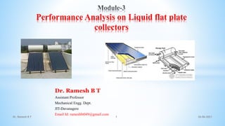
  • 1. Dr. Ramesh B T Assistant Professor Mechanical Engg. Dept. JIT-Davanagere Email Id: rameshbt049@gmail.com 26-06-2021 Dr. Ramesh B T 1 Performance Analysis on Liquid flat plate collectors
  • 10. 26-06-2021 Dr. Ramesh B T 10 • Effect of Shading • Collect Tilt • Fluid Inlet Temperature • Dust on the top Cover
  • 12. 26-06-2021 Dr. Ramesh B T 12 Stagnation temperature Stagnation temperature is the temperature reached when stagnation persists until the losses of the solar thermal collectors equal the absorbed energy. The stagnation temperature depends on the ambient conditions (ambient temperature and hemispherical irradiance) and reaches different values depending on these conditions. The standard stagnation temperature defined by the international standard EN ISO 9806:2013 /1/ give the value for the stagnation temperature at 1000 W/m² hemispherical irradiance and 30 °C ambient temperature. This standard stagnation temperature is usually used to describe the highest temperature reached by the solar thermal collectors Stagnation describes the state of a solar thermal system in which (by any reason) the flow in the collector loop is interrupted although sufficient solar irradiance is available for operation of the collector loop. If stagnation persists and solar irradiance is still being absorbed by the collector, temperatures and pressure in the collector loop will increase. When the temperature raises higher than the operation temperature, two things can happen: - The design temperature is reached: The solar thermal collectors or parts of the collector loop reach a temperature where (parts of) the collectors (or the collector loop) are damaged. Obviously, this has to be avoided using appropriate measures. If the first does not apply and the stagnation persists, the collectors reach their specific maximum absorber temperature (= stagnation temperature). This temperature depends on the collector design and the current weather conditions (mainly irradiance and ambient temperature) and the heat transfer medium conditions inside the collector and/or collector loop.
  • 13. 26-06-2021 Dr. Ramesh B T 13 Transmissivity of the Cover System
  • 19. 26-06-2021 Dr. Ramesh B T 19 The calculation is done in detail for one angle of incidence, viz. θ1=15◦. Hence, θ2 =sin−1[(sin15◦)/1.52]=9.80◦ ρI =sin2(9.80◦−15◦) sin2(9.80◦+15◦) =0.047 τrI =1−0.047 1+(3×0.047)=0.835 ρII =tan2(9.80◦−15◦) tan2(9.80◦+15◦)=0.039 τrII =1−0.039 1+(3×0.039)=0.860 τr =1/2(0.835+0.860) =0.848
  • 20. 26-06-2021 Dr. Ramesh B T 20 τd =0.885, τr = 0.848 τ =0.848×0.885 τ =0.750
  • 21. 26-06-2021 Dr. Ramesh B T 21 Transmissivity-absorptivity product The Transmissivity -absorptivity product is defined as the ratio of the flux absorbed in the absorber plate to the flux incident on the cover system, and is denoted by the symbol (τα), an appropriate subscript(b or d )being added to indicate the type of incident radiation. An expression for the Transmissivity absorptivity product will now be derived.
  • 22. 26-06-2021 Dr. Ramesh B T 22 The symbol ρd represents the diffuse reflectivity of the cover system. It can be found by determining the value τa (1−τr) for the cover system for an incidence angle of 60◦. From Example it is seen that ρd = 0.21 for a two glass cover system. Similarly, for a one-glass cover system, the value of ρd can be shown to be 0.15. Over all loss coefficient and heat transfer correlations Where, Ul = Over all loss coefficient. Ap = Area of the absorber plate. Tpm = Average temperature of the absorber plate. Ta = Average temperature of the absorber plate.
  • 23. 26-06-2021 Dr. Ramesh B T 23 The heat lost from the collector is the sum of the heat lost from the top, the bottom and the sides. Thus, Where, qt = Rate At which heat is lost from the top. qb = Rate at which heat is lost from the bottom. qs = Rate at which heat Is lost from the sides. It will be noted that the definition of each of the coefficients is based on the area Ap and the temperature difference (Tpm−Ta). This is done for convenience and helps in giving the simple additive equation
  • 24. 26-06-2021 Dr. Ramesh B T 24 The losses can also be shown in terms of thermal resistances as shown in Fig. The overall loss coefficient is an important parameter since it is a measure of all the losses. Typical values range from 2 to10 W/m2-K.
  • 25. 26-06-2021 Dr. Ramesh B T 25 Top loss coefficient
  • 26. 26-06-2021 Dr. Ramesh B T 26 Heat transfer coefficient between inclined parallel surfaces Heat transfer coefficient at the top cover
  • 27. 26-06-2021 Dr. Ramesh B T 27 Empirical equation for top loss coefficient
  • 28. 26-06-2021 Dr. Ramesh B T 28 Bottom loss coefficient Side loss coefficient
  • 30. 26-06-2021 Dr. Ramesh B T 30 i)From equation, sky temperature is calculated, Tsky =Ta−6=297.2−6=291.2 K ii)Using equation, we can calculate hw, hw =8.55+2.56V∞ =8.55+(2.56×2.5)=14.95 W/m2−K iii)Top loss coefficient can be found using empirical equation Where we need to find values of f and C first, f = (9/ hw −30/ hw2) (Ta /316.9)(1+0.091M)
  • 32. 26-06-2021 Dr. Ramesh B T 32 v) Side loss co-efficinet can be found using equation Us =(L1 +L2)L3Ki /(2L1L2δs) =(0.90×1.90)×(0.4+0.4+0.8)×0.05/0.90×1.90×0.04 Us = 0.33 W/m2−K
  • 33. 26-06-2021 Dr. Ramesh B T 33 Temperature Distribution between the Tubes it is desirable to have an understanding of the temperature distribution that exists in a solar collector constructed as shown in below Figure shows a region between two tubes. Some of the solar energy absorbed by the plate must be conducted along the plate to the region of the tubes, thus the temperature midway between the tubes will be higher than tube temperature in the . vicinity of the tubes. The temperature above the tubes will be nearly uniform because of the presence of the tube and weld metal. The energy transferred to the fluid will heat the fluid, causing a temperature gradient to exist in the direction of flow. Since in any region of the collector the general temperature level is governed by the local temperature level of the fluid, a situation as shown in Figure is expected At any location y, the general temperature distribution in the x direction is as shown in Figure and at any location x, the temperature distribution in the y direction will look like Figure.
  • 34. 26-06-2021 Dr. Ramesh B T 34 To model the situation shown in Figure , a number of simplifying assumptions can be made to lay the foundations without obscuring the basic physical situation. These assumptions are as follows: _ 1. Performance is steady state. 2. Construction is of sheet and parallel tube type. 3. The headers cover a small area of collector and can be neglected. 4. The headers provide uniform flow to tubes. 5. There is no absorption of solar energy by a cover insofar as it affects losses from the collector. 6. Heat flow through a cover is one dimensional. 7. There is a negligible temperature drop through a cover. 8. The covers are opaque to infrared radiation. 9. There is one-dimensional heat flow through back insulation. 10.The sky can be considered as a blackbody for long-wavelength radiation at an equivalent sky temperature. . 11.Temperature gradients around tubes can be neglected. 12.The temperature gradients in the direction of flow and between the tubes can be., -- treated- independently. 13.Properties are independent of temperature. 14.Loss through front and back are to the same ambient temperature. 15. Dust and dirt on the collector are negligible. 16. Shading of the collector absorber plate is negligible
  • 35. 26-06-2021 Dr. Ramesh B T 35 Collector efficiency factor
  • 38. 26-06-2021 Dr. Ramesh B T 38 Next we consider the flow of heat from the plate to the fluid. The three thermal resistances in the path are due to the adhesive used for attaching the tubes to the absorber plate, the tube wall and the heat transfer coefficient at the inner surface of the tube. Assuming the thermal resistance of the tube wall to be negligible.
  • 39. 26-06-2021 Dr. Ramesh B T 39 Where, F0 represents the ratio of the actual useful gain rate per tube per unit length to the gain which would occur, if the collector absorber plate where at the temperature Tf
  • 40. 26-06-2021 Dr. Ramesh B T 40 Collector heat removal factor
  • 41. 26-06-2021 Dr. Ramesh B T 41 The term FR is called the collector heat-removal factor. It is an important design parameter since it is a measure of the thermal resistance encountered by the absorbed solar radiation in reaching the collector fluid. From above Eq, it can be seen that FR represents the ratio of the actual useful heat gain rate to the gainwhichwouldoccurifthecollectorabsorberplatewasatthetemperature Tf i every where. As such its value ranges between 0 and 1.
  • 43. 26-06-2021 Dr. Ramesh B T 43 ii)Solar hour angle ωs =0, (at mean of11:30and12:30), iii)Solar altitude angle αa is given by, sinαa =cosφcosδcosωs +sinφsinδ =cos22◦cos(−23◦)cos0◦+sin22◦sin(−23◦) =0.85−0.146 =0.7036 αa =44.7◦ ...(Ans.) iv)Incident angle θ, θ = π 2 −αa =90−44.7◦ θ =45.3◦ ...(Ans.)
  • 45. 26-06-2021 Dr. Ramesh B T 45 viii)Now, S =HbRb(τα) =350×1.40×0.811 S =395 W/m2 =340.62 kcal/hr m2
  • 46. 26-06-2021 Dr. Ramesh B T 46 Effect of various parameters on collector performance a)Heat transfer system b)Selective surface c)Number of covers d)Collector tilt e)Spacing f)Fluid temperature g)Cover transmissivity h)Dust on top of the cover i)Performance over a day
  • 47. 26-06-2021 Dr. Ramesh B T 47 Photovoltaic Cell Definition: The Photovoltaic cell is the semiconductor device that converts the light into electrical energy. The voltage induces by the PV cell depends on the intensity of light incident on it. The name Photovoltaic is because of their voltage producing capability. The energises electron is known as the Photoelectrons. And the phenomenon of emission of electrons is known as the photoelectric effect. The working of the Photovoltaic cell depends on the photoelectric effect
  • 48. 26-06-2021 Dr. Ramesh B T 48 Construction of Photovoltaic Cell The semiconductor materials like arsenide, indium, cadmium, silicon, selenium and gallium are used for making the PV cells. Mostly silicon and selenium are used for making the cell. Consider the figure below shows the constructions of the silicon photovoltaic cell. The output voltage and current obtained from the single unit of the cell is very less. The magnitude of the output voltage is 0.6v, and that of the current is 0.8v. The different combinations of cells are used for increasing the output efficiency. There are three possible ways of combining the PV cells.
  • 49. 26-06-2021 Dr. Ramesh B T 49 Series Combination of PV Cells If more than two cells are connected in series with each other, then the output current of the cell remains same, and their input voltage becomes doubles. The graph below shows the output characteristic of the PV cells when connected in series. Parallel Combination of PV cells In the parallel combination of the cells, the voltage remains same, and the magnitude of current becomes double. The characteristic curve of the parallel combination of cells is represented below.
  • 50. 26-06-2021 Dr. Ramesh B T 50 Series-Parallel Combination of PV cells In the series-parallel combination of cells the magnitude of both the voltage and current increases. Thereby, the solar panels are made by using the series-parallel combination of the cells. The solar module is constructed by connecting the single solar cells. And the combination of the solar modules together is known as the solar panel.
  • 51. 26-06-2021 Dr. Ramesh B T 51 Working of PV cell The light incident on the semiconductor material may be pass or reflected through it. The PV cell is made of the semiconductor material which is neither a complete conductor nor an insulator. This property of semiconductor material makes it more efficient for converting the light energy into electric energy.
  • 52. 26-06-2021 Dr. Ramesh B T 52 How Solar Cell Install on the Solar Power Plant? Maximum power point tracker, inverter, charge controller and battery are the name of the apparatus used for converting the radiation into an electrical voltage.
  • 53. 26-06-2021 Dr. Ramesh B T 53 Photovoltaic Applications • Solar Farms. Many acres of PV panels can provide utility-scale • power—from tens of megawatts to more than a gigawatt of electricity. ... • Remote Locations. ... • Stand-Alone Power. ... • Power in Space. ... • Building-Related Needs. ... • Military Uses. ... • Transportation.
  • 54. 26-06-2021 Dr. Ramesh B T 54 Thank YOU