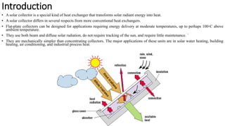
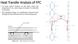
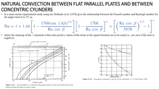
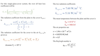
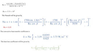
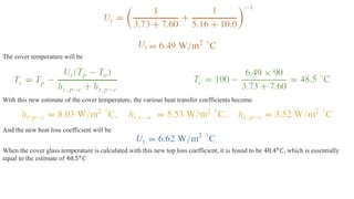
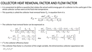
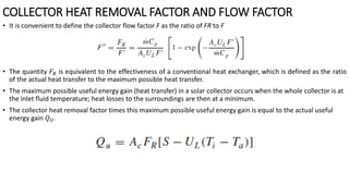
Flat Plate Collectors
Lecture 6
Introduction
• A solar collector is a special kind of heat exchanger that transforms solar radiant energy into heat.
• A solar collector differs in several respects from more conventional heat exchangers.
• Flat-plate collectors can be designed for applications requiring energy delivery at moderate temperatures, up to perhaps 100◦C above
ambient temperature.
• They use both beam and diffuse solar radiation, do not require tracking of the sun, and require little maintenance. `
• They are mechanically simpler than concentrating collectors. The major applications of these units are in solar water heating, building
heating, air conditioning, and industrial process heat.
Description of Flat Plate Collectors (FPC)
• The important parts of a typical liquid heating flat-plate solar collector, ‘‘black’’ solar energy-absorbing surface
with means for transferring the absorbed energy to a fluid, envelopes transparent to solar radiation over the solar
absorber surface that reduce convection and radiation losses to the atmosphere, and back insulation to reduce
conduction losses.
• Flat-plate collectors are almost always mounted in a stationary position (e.g., as an integral part of a wall or roof
structure)
Basic Energy Equation
• In steady state, the performance of a solar collector is described by an energy balance
that indicates the distribution of incident solar energy into useful energy gain,
thermal losses, and optical losses.
• In steady state the useful energy output of a collector of area 𝐴𝐶is the difference
between the absorbed solar radiation and the thermal loss:
• Here, S is the total radiation absorbed by the collector, 𝑈𝐿is the heat loss coefficient,
𝑇𝑝𝑚 is the mean temperature of the plate and 𝑇𝑎 is the ambient temperature.
• The problem with this equation is that the mean absorber plate temperature is
difficult to calculate or measure since it is a function of the collector design, the
incident solar radiation, and the entering fluid conditions.
• A measure of collector performance is the collection efficiency, defined as the ratio
of the useful gain over some specified time period to the incident solar energy over
the same time period:
• If conditions are constant over a time period, the efficiency reduces to
Heat Transfer Analysis of FPC
Assumptions for the analysis
1. Performance is steady state.
2. Construction is of sheet and parallel tube type.
3. The headers cover a small area of collector and can be
neglected.
4. The headers provide uniform flow to tubes.
5. There is no absorption of solar energy by a cover in so far as it
affects losses from the collector.
6. Heat flow through a cover is one dimensional.
7. There is a negligible temperature drop through a cover.
8. The covers are opaque to infrared radiation.
9. There is one-dimensional heat flow through back insulation.
10. The sky can be considered as a blackbody for long-
wavelength radiation at an equivalent sky temperature.
11. Temperature gradients around tubes can be neglected.
12. The temperature gradients in the direction of flow and
between the tubes can be treated independently.
13. Properties are independent of temperature.
14. Loss through front and back are to the same ambient
temperature.
15. Dust and dirt on the collector are negligible.
16. Shading of the collector absorber plate is negligible.
• At some typical location on the plate where the
temperature is 𝑇𝑝, solar energy of amount S is absorbed
by the plate.
• This absorbed energy S is distributed to thermal losses
through the top and bottom and to useful energy gain.
Heat Transfer Analysis of FPC
Heat
loss
• The steady-state energy transfer between the plate at 𝑇𝑝 and the first cover at 𝑇𝐶1 is the
same as between any other two adjacent covers and is also equal to the energy lost to the
surroundings from the top cover.
• The loss through the top per-unit area is then equal to the heat transfer from the absorber
plate to the first cover:
• where ℎ𝑐,𝑝−𝑐1 is the convection heat transfer coefficient between two inclined parallel
plates
• If the definition of the radiation heat transfer coefficient is used, the heat loss becomes
• The resistance 𝑅3 can then be expressed as
• A similar expression can be written for 𝑅2 , the resistance between the covers.
Heat Transfer Analysis of FPC
• The resistance to the surroundings 𝑅1 is then given by
• where ℎ𝑟,𝑐2−𝑎 is the radiation heat transfer coefficient between collector 2 and air.
• where ℎ𝑤 is the convective heat transfer coefficient between cover 2 and air.
• V is the velocity of wind. For this two-cover system, the top loss coefficient from the
collector plate to the ambient is
• Beginning at the absorber plate, a new temperature is calculated for the first cover. This
new first cover temperature is used to find the next cover temperature, and so on. For
any two adjacent covers or plate, the new temperature of plate or cover j can be
expressed in terms of the temperature of plate or cover i as
Heat Transfer Analysis of FPC
ℎ𝑤 = 2.8 + 3.0𝑉
NATURAL CONVECTION BETWEEN FLAT PARALLEL PLATES AND BETWEEN
CONCENTRIC CYLINDERS
• The rate of heat transfer between two plates inclined at some angle to the horizon is of obvious importance in the performance
of flat-plate collectors.
• Free-convection heat transfer data are usually correlated in terms of two or three dimensionless parameters: the Nusselt number
Nu, the Rayleigh number Ra, and the Prandtl number Pr
• The Nusselt, Rayleigh, and Prandtl numbers are given by
• In a more recent experimental study using air, Hollands et al. (1976) give the relationship between the Nusselt number and Rayleigh number for
tilt angles from 0 to 75◦ as
• where the meaning of the + exponent is that only positive values of the terms in the square brackets are to be used (i.e., use zero if the term is
negative).
NATURAL CONVECTION BETWEEN FLAT PARALLEL PLATES AND BETWEEN
CONCENTRIC CYLINDERS
Heat Loss
For this single-glass-cover system, the over all heat loss
coefficient will be
The radiation coefficient from the plate to the cover ℎ𝑟,𝑝−𝑐
is
The radiation coefficient for the cover to the air ℎ𝑟,𝑐−𝑎 is
given as
𝐴𝑠𝑠𝑢𝑚𝑒 𝑇𝑐 = 35𝑜
𝐶
The two radiation coefficients
The mean temperature between the plate and the cover is
𝑇𝑚 = 67.5𝑜
𝐶
The air properties are
𝜈 = 1.96 × 10⁻⁵ Τ
𝑚2 𝑠
𝑘 = 0.0293 𝑊/𝑚𝐾
𝑃𝑟 = 0.7
𝑇𝑚 = 340.5 𝐾
The Rayleigh number is
The Nusselt will be given by
𝑁𝑢 = 3.19
The convective heat transfer coefficient is
The heat loss coefficient will be given by
The cover temperature will be
With this new estimate of the cover temperature, the various heat transfer coefficients become
And the new heat loss coefficient will be
When the cover glass temperature is calculated with this new top loss coefficient, it is found to be 48.4𝑜
𝐶, which is essentially
equal to the estimate of 48.5𝑜
𝐶
COLLECTOR HEAT REMOVAL FACTOR AND FLOW FACTOR
• It is convenient to define a quantity that relates the actual useful energy gain of a collector to the useful gain if the
whole collector surface were at the fluid inlet temperature.
• This quantity is called the collector heat removal factor 𝐹𝑅. In equation form it is
• The collector heat removal factor can be expressed as
• 𝐹′is the collector efficiency factor
• This collector flow factor is a function of the single variable, the dimensionless collector capacitance rate
Also
• It is convenient to define the collector flow factor F as the ratio of FR to F
• The quantity 𝐹𝑅 is equivalent to the effectiveness of a conventional heat exchanger, which is defined as the ratio
of the actual heat transfer to the maximum possible heat transfer.
• The maximum possible useful energy gain (heat transfer) in a solar collector occurs when the whole collector is at
the inlet fluid temperature; heat losses to the surroundings are then at a minimum.
• The collector heat removal factor times this maximum possible useful energy gain is equal to the actual useful
energy gain 𝑄𝑈.
COLLECTOR HEAT REMOVAL FACTOR AND FLOW FACTOR
Direct Active solar heating
Indirect solar passive heating system
Parabolic trough collector
• For many applications it is desirable to deliver energy at temperatures higher
than those possible with flat-plate collectors.
• Energy delivery temperatures can be increased by decreasing the area from
which heat losses occur.
• This is done by interposing an optical device between the source of radiation
and the energy-absorbing surface.
• Concentrators can be reflectors or refractors, can be cylindrical or surfaces of
revolution, and can be continuous or segmented.
• To avoid confusion of terminology, the word collector will be applied to the
total system, including the receiver and the concentrator.
• The receiver is that element of the system where the radiation is absorbed
and converted to some other energy form; it includes the absorber, its
associated covers, and insulation.
CONCENTRATION RATIO
• The ratio of the area of aperture to the area of the receiver.
Typical application of parabolic trough collector(linear)
Parabolic dish 3D collector
Solar tower spain
Crescent dunes solar tower

Flate Plate Collector (theory presentation).pdf

  • 1.
  • 2.
    Introduction • A solarcollector is a special kind of heat exchanger that transforms solar radiant energy into heat. • A solar collector differs in several respects from more conventional heat exchangers. • Flat-plate collectors can be designed for applications requiring energy delivery at moderate temperatures, up to perhaps 100◦C above ambient temperature. • They use both beam and diffuse solar radiation, do not require tracking of the sun, and require little maintenance. ` • They are mechanically simpler than concentrating collectors. The major applications of these units are in solar water heating, building heating, air conditioning, and industrial process heat.
  • 3.
    Description of FlatPlate Collectors (FPC) • The important parts of a typical liquid heating flat-plate solar collector, ‘‘black’’ solar energy-absorbing surface with means for transferring the absorbed energy to a fluid, envelopes transparent to solar radiation over the solar absorber surface that reduce convection and radiation losses to the atmosphere, and back insulation to reduce conduction losses. • Flat-plate collectors are almost always mounted in a stationary position (e.g., as an integral part of a wall or roof structure)
  • 4.
    Basic Energy Equation •In steady state, the performance of a solar collector is described by an energy balance that indicates the distribution of incident solar energy into useful energy gain, thermal losses, and optical losses. • In steady state the useful energy output of a collector of area 𝐴𝐶is the difference between the absorbed solar radiation and the thermal loss: • Here, S is the total radiation absorbed by the collector, 𝑈𝐿is the heat loss coefficient, 𝑇𝑝𝑚 is the mean temperature of the plate and 𝑇𝑎 is the ambient temperature. • The problem with this equation is that the mean absorber plate temperature is difficult to calculate or measure since it is a function of the collector design, the incident solar radiation, and the entering fluid conditions. • A measure of collector performance is the collection efficiency, defined as the ratio of the useful gain over some specified time period to the incident solar energy over the same time period: • If conditions are constant over a time period, the efficiency reduces to
  • 5.
    Heat Transfer Analysisof FPC Assumptions for the analysis 1. Performance is steady state. 2. Construction is of sheet and parallel tube type. 3. The headers cover a small area of collector and can be neglected. 4. The headers provide uniform flow to tubes. 5. There is no absorption of solar energy by a cover in so far as it affects losses from the collector. 6. Heat flow through a cover is one dimensional. 7. There is a negligible temperature drop through a cover. 8. The covers are opaque to infrared radiation. 9. There is one-dimensional heat flow through back insulation. 10. The sky can be considered as a blackbody for long- wavelength radiation at an equivalent sky temperature. 11. Temperature gradients around tubes can be neglected. 12. The temperature gradients in the direction of flow and between the tubes can be treated independently. 13. Properties are independent of temperature. 14. Loss through front and back are to the same ambient temperature. 15. Dust and dirt on the collector are negligible. 16. Shading of the collector absorber plate is negligible.
  • 6.
    • At sometypical location on the plate where the temperature is 𝑇𝑝, solar energy of amount S is absorbed by the plate. • This absorbed energy S is distributed to thermal losses through the top and bottom and to useful energy gain. Heat Transfer Analysis of FPC Heat loss
  • 7.
    • The steady-stateenergy transfer between the plate at 𝑇𝑝 and the first cover at 𝑇𝐶1 is the same as between any other two adjacent covers and is also equal to the energy lost to the surroundings from the top cover. • The loss through the top per-unit area is then equal to the heat transfer from the absorber plate to the first cover: • where ℎ𝑐,𝑝−𝑐1 is the convection heat transfer coefficient between two inclined parallel plates • If the definition of the radiation heat transfer coefficient is used, the heat loss becomes • The resistance 𝑅3 can then be expressed as • A similar expression can be written for 𝑅2 , the resistance between the covers. Heat Transfer Analysis of FPC
  • 8.
    • The resistanceto the surroundings 𝑅1 is then given by • where ℎ𝑟,𝑐2−𝑎 is the radiation heat transfer coefficient between collector 2 and air. • where ℎ𝑤 is the convective heat transfer coefficient between cover 2 and air. • V is the velocity of wind. For this two-cover system, the top loss coefficient from the collector plate to the ambient is • Beginning at the absorber plate, a new temperature is calculated for the first cover. This new first cover temperature is used to find the next cover temperature, and so on. For any two adjacent covers or plate, the new temperature of plate or cover j can be expressed in terms of the temperature of plate or cover i as Heat Transfer Analysis of FPC ℎ𝑤 = 2.8 + 3.0𝑉
  • 9.
    NATURAL CONVECTION BETWEENFLAT PARALLEL PLATES AND BETWEEN CONCENTRIC CYLINDERS • The rate of heat transfer between two plates inclined at some angle to the horizon is of obvious importance in the performance of flat-plate collectors. • Free-convection heat transfer data are usually correlated in terms of two or three dimensionless parameters: the Nusselt number Nu, the Rayleigh number Ra, and the Prandtl number Pr • The Nusselt, Rayleigh, and Prandtl numbers are given by
  • 10.
    • In amore recent experimental study using air, Hollands et al. (1976) give the relationship between the Nusselt number and Rayleigh number for tilt angles from 0 to 75◦ as • where the meaning of the + exponent is that only positive values of the terms in the square brackets are to be used (i.e., use zero if the term is negative). NATURAL CONVECTION BETWEEN FLAT PARALLEL PLATES AND BETWEEN CONCENTRIC CYLINDERS
  • 12.
  • 13.
    For this single-glass-coversystem, the over all heat loss coefficient will be The radiation coefficient from the plate to the cover ℎ𝑟,𝑝−𝑐 is The radiation coefficient for the cover to the air ℎ𝑟,𝑐−𝑎 is given as 𝐴𝑠𝑠𝑢𝑚𝑒 𝑇𝑐 = 35𝑜 𝐶 The two radiation coefficients The mean temperature between the plate and the cover is 𝑇𝑚 = 67.5𝑜 𝐶 The air properties are 𝜈 = 1.96 × 10⁻⁵ Τ 𝑚2 𝑠 𝑘 = 0.0293 𝑊/𝑚𝐾 𝑃𝑟 = 0.7 𝑇𝑚 = 340.5 𝐾 The Rayleigh number is
  • 14.
    The Nusselt willbe given by 𝑁𝑢 = 3.19 The convective heat transfer coefficient is The heat loss coefficient will be given by
  • 15.
    The cover temperaturewill be With this new estimate of the cover temperature, the various heat transfer coefficients become And the new heat loss coefficient will be When the cover glass temperature is calculated with this new top loss coefficient, it is found to be 48.4𝑜 𝐶, which is essentially equal to the estimate of 48.5𝑜 𝐶
  • 16.
    COLLECTOR HEAT REMOVALFACTOR AND FLOW FACTOR • It is convenient to define a quantity that relates the actual useful energy gain of a collector to the useful gain if the whole collector surface were at the fluid inlet temperature. • This quantity is called the collector heat removal factor 𝐹𝑅. In equation form it is • The collector heat removal factor can be expressed as • 𝐹′is the collector efficiency factor • This collector flow factor is a function of the single variable, the dimensionless collector capacitance rate Also
  • 17.
    • It isconvenient to define the collector flow factor F as the ratio of FR to F • The quantity 𝐹𝑅 is equivalent to the effectiveness of a conventional heat exchanger, which is defined as the ratio of the actual heat transfer to the maximum possible heat transfer. • The maximum possible useful energy gain (heat transfer) in a solar collector occurs when the whole collector is at the inlet fluid temperature; heat losses to the surroundings are then at a minimum. • The collector heat removal factor times this maximum possible useful energy gain is equal to the actual useful energy gain 𝑄𝑈. COLLECTOR HEAT REMOVAL FACTOR AND FLOW FACTOR
  • 18.
  • 19.
    Indirect solar passiveheating system
  • 20.
    Parabolic trough collector •For many applications it is desirable to deliver energy at temperatures higher than those possible with flat-plate collectors. • Energy delivery temperatures can be increased by decreasing the area from which heat losses occur. • This is done by interposing an optical device between the source of radiation and the energy-absorbing surface. • Concentrators can be reflectors or refractors, can be cylindrical or surfaces of revolution, and can be continuous or segmented. • To avoid confusion of terminology, the word collector will be applied to the total system, including the receiver and the concentrator. • The receiver is that element of the system where the radiation is absorbed and converted to some other energy form; it includes the absorber, its associated covers, and insulation. CONCENTRATION RATIO • The ratio of the area of aperture to the area of the receiver.
  • 21.
    Typical application ofparabolic trough collector(linear)
  • 22.
  • 23.
  • 25.