1. Prof. Dr. Hesham Mostafa, HTI, Mech. Eng. Dept., Heat &Mass Transfer, ME209, Sep. 2014 Page 1
اﻟﺮﺣﯿﻢ اﻟﺮﺣﻤﻦ اﷲ ﺑﺴﻢ
HTI, Mech. Eng. Dept., Heat and Mass Transfer ME 209
Prof. Dr. Hesham Mostafa & Eng. Ahmed Samy
Week number (1), ( I )
Lecture (1)
Introduction
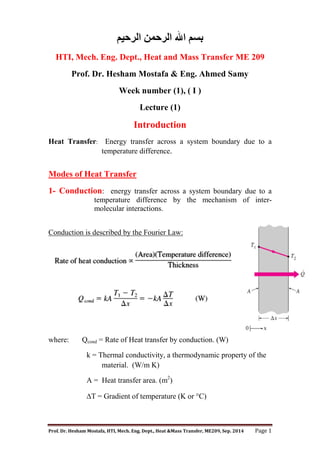
Heat Transfer: Energy transfer across a system boundary due to a
temperature difference.
Modes of Heat Transfer
1- Conduction: energy transfer across a system boundary due to a
temperature difference by the mechanism of inter-
molecular interactions.
Conduction is described by the Fourier Law:
where: Qcond = Rate of Heat transfer by conduction. (W)
k = Thermal conductivity, a thermodynamic property of the
material. (W/m K)
A = Heat transfer area. (m2
)
T = Gradient of temperature (K or C)
2. Prof. Dr. Hesham Mostafa, HTI, Mech. Eng. Dept., Heat &Mass Transfer, ME209, Sep. 2014 Page 2
2- Convection: energy transfer across
a system boundary due to a temperature
difference by the combined mechanisms
of intermolecular interactions and bulk
transport.
Convection Heat transfer can be
classified into; forced convection
and free convection.
Newton’s Law of Cooling:
3- Radiation: energy transfer across a system boundary due to a
temperature difference by the mechanism of photon emission
or electromagnetic waves.
Stefan-Boltzman Law:
Eb = T4
where: Eb = Gross heat emission by an ideal surface per unit area (W/m2
)
σ = Steffan Boltzman constant = 5.67 x 10⁻⁸
W/m2
K4
.
T = Absolute temperature. ( K)
3. Prof. Dr. Hesham Mostafa, HTI, Mech. Eng. Dept., Heat &Mass Transfer, ME209, Sep. 2014 Page 3
The rate of radiant heat transfer between an object and its surroundings
Qrad = ε·σ·A·(Tobj
4
- T
4
)
where: ε = Surface Emissivity, -
A= Surface Area, m2
Tobj = Absolute temperature of surface. ( K)
Tj = Absolute temperature of surroundings.( K)
4- Boiling Heat Transfer: is phase change process occurs at the
solid–liquid interface when a liquid is brought into contact with
a surface maintained at a temperature Ts sufficiently above the
saturation temperature Tsat of the liquid.
5- Condensation: Occurs when the temperature of a vapor is reduced
below its saturation temperature Tsat. This is usually done
by bringing the vapor into contact with a solid surface
whose temperature Ts is below the saturation temperature
Tsat of the vapor.
4. Prof. Dr. Hesham Mostafa, HTI, Mech. Eng. Dept., Heat &Mass Transfer, ME209, Sep. 2014 Page 4
اﻟﺮﺣﯿﻢ اﻟﺮﺣﻤﻦ اﷲ ﺑﺴﻢ
Week number (1), ( II )
Lecture (2)
One Dimension Conduction Heat transfer
1) In Plane Wall
Fourier's equation:
Q kA
dT
dx
where: Qcond = Conduction Heat transfer, (W).
k = Thermal conductivity, (W/m K).
A = Heat transfer area, (m2
).
T = Temperature, (K or C).
x = Distance, (m).
Fourier's equation applied with the following Conditions:
One dimension conduction heat transfer
Steady state
Constant properties
No heat generation
Q k
dT
dx
dT
Q
A
dx
k
T
Q
A
x
k
C
5. Prof. Dr. Hesham Mostafa, HTI, Mech. Eng. Dept., Heat &Mass Transfer, ME209, Sep. 2014 Page 5
Boundary Condition
@ x=0, T=T1
C=T1
T
Q
A
x
k
T
Put q''=Heat flux =Q/A
T T q′′
x
k
@ x = L, T = T2
T T q′′
k
q′′
Heat Conduction in Multilayer Plane Wall
q′′
T1 – T4 = q'' [ +
q'' =
∑
L1 L2 L3
T1
T2
T3
T4
K1 K2 K3
6. Prof. Dr. Hesham Mostafa, HTI, Mech. Eng. Dept., Heat &Mass Transfer, ME209, Sep. 2014 Page 6
,for n layers;
q'' =
∑
2) In cylindrical wall
Fourier's equation:
Q kA
dT
dr
Q k2rL
dT
dr
, where: Qcond = Rate of Heat transfer, W.
k = Thermal conductivity, (W/m K).
A = Heat transfer area, (m2
).
T = Temperature, (K or C).
Fourier's equation applied with the following Conditions:
One dimension conduction heat transfer
Steady state
Constant properties
No heat generation
dT
Q
2kL
dr
r
T
ln r C
Boundary Condition
@ r = r1, T = T1
T
Q
2kL
ln r C
7. Prof. Dr. Hesham Mostafa, HTI, Mech. Eng. Dept., Heat &Mass Transfer, ME209, Sep. 2014 Page 7
C = T1 +
ln r
T =
ln r T
ln r
T = T1 -
ln r lnr
T = T1 -
ln r
r
This is the temperature distribution
To find the amount of heat transfer by conduction in cylindrical wall;
@ r = r2, T = T2
T2 = T1 -
ln
r
r
1
2
ln
Heat Conduction in Multi-layers (n layers ) for Cylindrical wall;
1
2
∑
1
k
ln
8. Prof. Dr. Hesham Mostafa, HTI, Mech. Eng. Dept., Heat &Mass Transfer, ME209, Sep. 2014 Page 8
اﻟﺮﺣﯿﻢ اﻟﺮﺣﻤﻦ اﷲ ﺑﺴﻢ
Week number (2), ( I )
Lecture (3)
Application on one dimension Conduction heat transfer
Example 1
- For comosite plane wall of an oven;
LA = Lc =0.1 m
LB = 0.4 m , KA = 50 w/mC
Kc = 0.5 w/mC
T1= 600 C T=20C
T4= 50 C h=100 w/m2
C
Find The thermal conductivity for wall (B)
Solution
Q = A
= . . .
.
100 50 20
KB =
T1
T2
T3
LA LB Lc
KA KB KC
T4
Fluid
h, T
9. Prof. Dr. Hesham Mostafa, HTI, Mech. Eng. Dept., Heat &Mass Transfer, ME209, Sep. 2014 Page 9
Example 2
The upper surface of Insulated rod (k = 50 w/mC, L=1 m )was
maintained at 100C and the lower surface is cooled by fluid at
30 C with h=50 w/m2
C.
Find the temperature at midpoint for rod shown in figure:
T1= 100 C
T = 30 C
Solution
Heat flow in axial Direction
3
q′′
50 30
T3 = C
q'' = w/ m2
T1
T3
T2
L1=0.5 m
Fluid
h, T
L2=0.5 m
10. Prof. Dr. Hesham Mostafa, HTI, Mech. Eng. Dept., Heat &Mass Transfer, ME209, Sep. 2014 Page 10
To find T2
q′′
1
100
0.5
50
T2 = C
General heat conduction equation
Qx = - KA (∂T/∂x) = -k (dydz) (∂T/∂x)
Qx+dx= Qx +
∂
∂
Qx = -
∂
∂
∂
∂
dx
Qy = -
∂
∂
∂
∂
dy
Qz = -
∂
∂
∂
∂
dz
Therefore, the general heat conduction equation is found in the following form;
∂
∂
k ∂
∂
∂
∂
k
∂T
∂y
∂
∂
k
∂T
∂z
+ =
qv
12. Prof. Dr. Hesham Mostafa, HTI, Mech. Eng. Dept., Heat &Mass Transfer, ME209, Sep. 2014 Page 12
اﻟﺮﺣﯿﻢ اﻟﺮﺣﻤﻦ اﷲ ﺑﺴﻢ
Solved Examples
"Part One"
Ex.1) Consider a 1.2-m-high and 2-m-wide double-pane window
consisting of two 3-mm-thick layers of glass (k =0.78 W/m °C) separated
by a 12-mm-wide stagnant air space (k = 0.026 W/m °C). Determine the
steady rate of heat transfer through this double-pane window and the
temperature of its inner surface for a day during which the room is
maintained at 24°C while the temperature of the outdoors is -5°C. Take
the convection heat transfer coefficients on the inner and outer surfaces of
the window to be 10 W/m2
°C and 25 W/m2
°C respectively.
Solution
Assumptions 1 Heat transfer through the window is steady since the indoor and
outdoor temperatures remain constant at the specified values. 2 Heat transfer is one-
dimensional since any significant temperature gradients will exist in the direction
from the indoors to the outdoors. 3 Thermal conductivities of the glass and air are
constant. 4 Heat transfer by radiation is negligible.
Properties The thermal conductivity of the glass and air are given to be kglass = 0.78
W/m°C and kair = 0.026 W/m°C.
The area of the window and the individual resistances are
A
( . ( .
12 2 2 4
m) m) m2
C/W
2539
.
0
0167
.
0
1923
.
0
)
0016
.
0
(
2
0417
.
0
2
C/W
0167
.
0
)
m
4
.
2
(
C)
.
W/m
25
(
1
1
C/W
1923
.
0
)
m
4
.
2
(
C)
W/m.
026
.
0
(
m
012
.
0
C/W
0016
.
0
)
m
4
.
2
(
C)
W/m.
78
.
0
(
m
003
.
0
C/W
0417
.
0
)
m
4
.
2
(
C)
.
W/m
10
(
1
1
2
,
2
1
1
,
o
2
o
2
2
2
,
o
2
2
2
2
2
1
1
glass
3
1
2
2
1
1
,
i
conv
conv
total
conv
air
conv
R
R
R
R
R
A
h
R
R
A
k
L
R
R
A
k
L
R
R
R
A
h
R
R
The steady rate of heat transfer through window glass then becomes
W
114
C/W
2539
.
0
C
)]
5
(
24
[
2
1
total
R
T
T
Q
The inner surface temperature of the window glass can be determined from
C
19.2
=
C/W)
W)(0.0417
114
(
C
24o
1
,
1
1
1
,
1
1
conv
conv
R
Q
T
T
R
T
T
Q
Air
R1 R2 R3 Ro
Ri
T1 T2
13. Prof. Dr. Hesham Mostafa, HTI, Mech. Eng. Dept., Heat &Mass Transfer, ME209, Sep. 2014 Page 13
Ex. 2) A 2-m1.5-m section of wall of an industrial furnace burning
natural gas is not insulated, and the temperature at the outer surface of
this section is measured to be 80°C. The temperature of the furnace room
is 30°C, and the combined convection and radiation heat transfer
coefficient at the surface of the outer furnace is 10 W/m2
°C. It is
proposed to insulate this section of the furnace wall with glass wool
insulation (k = 0.038 W/m °C) in order to reduce the heat loss by 90 %.
Assuming the outer surface temperature of the metal section still remains
at about 80°C; determine the thickness of the insulation that needs to be
used.
Solution
Assumptions 1 Heat transfer through the wall is steady and one-dimensional. 2
Thermal conductivities are constant. 3 The furnace operates continuously. 4 The
given heat transfer coefficient accounts for the radiation effects.
Properties The thermal conductivity of the glass wool insulation is given to be k =
0.038 W/m°C.
The rate of heat transfer without insulation is
A
(2 3
m)(1.5 m) m2
( ) ( . ( )(80 )
Q hA T T
s
10 3 30 1500
W / m C) m C W
2 2
In order to reduce heat loss by 90%, the new heat
transfer rate and thermal resistance must be
.
( )
.
Q
Q
T
R
R
T
Q
total
total
010 1500 150
80 30
150
0 333
W W
C
W
C / W
,and in order to have this thermal resistance, the thickness of insulation must be
cm
3.4
m
034
.
0
C/W
333
.
0
)
m
C)(3
W/m.
038
.
0
(
)
m
C)(3
.
W/m
10
(
1
1
2
2
2
conv
L
L
kA
L
hA
R
R
R insulation
total
Insulation
Ro
T
Rinsulation
Ts
L
14. Prof. Dr. Hesham Mostafa, HTI, Mech. Eng. Dept., Heat &Mass Transfer, ME209, Sep. 2014 Page 14
Ex. 3) Water is boiling in a 25-cm-diameter aluminum pan (k = 237 W/m
°C) at 95°C. Heat is transferred steadily to the boiling water in the pan
through its 0.5-cm-thick flat bottom at a rate of 800 W. If the inner
surface temperature of the bottom of the pan is 108°C, determine (a) the
boiling heat transfer coefficient on the inner surface of the pan, and (b)
the outer surface temperature of the bottom of the pan.
Solution
Assumptions 1 Steady operating conditions exist. 2 Heat transfer is one-dimensional
since the thickness of the bottom of the pan is small relative to its diameter. 3 The
thermal conductivity of the pan is constant.
Properties The thermal conductivity of the aluminum pan is given to be k = 237
W/m°C.
a) The boiling heat transfer coefficient is
2
2
2
m
0491
.
0
4
m)
25
.
0
(
4
D
As
C
.
W/m
1254 2
C
)
95
108
)(
m
0491
.
0
(
W
800
)
(
)
(
2
T
T
A
Q
h
T
T
hA
Q
s
s
s
s
(b) The outer surface temperature of the bottom of the pan is
C
108.3
)
m
C)(0.0491
W/m.
237
(
m)
005
.
0
W)(
800
(
+
C
108 2
1
,
,
,
,
kA
L
Q
T
T
L
T
T
kA
Q
inner
s
outer
s
inner
s
outer
s
95C
108C
600 W
0.5 cm
15. Prof. Dr. Hesham Mostafa, HTI, Mech. Eng. Dept., Heat &Mass Transfer, ME209, Sep. 2014 Page 15
Ex. 4) Two 5-cm-diameter, 15–cm-long
aluminum bars (k = 176 W/m °C) with
ground surfaces are pressed against each
other with a pressure of 20 atm (h =
11,400 W/m2
C). The bars are enclosed
in an insulation sleeve and, thus, heat
transfer from the lateral surfaces is negligible. If the top and bottom
surfaces of the two-bar system are maintained at temperatures of 150°C
and 20°C, respectively, determine (a) the rate of heat transfer along the
cylinders under steady conditions and (b) the temperature drop at the
interface.
Solution
Assumptions 1 Steady operating conditions exist. 2 Heat transfer is one-dimensional
in the axial direction since the lateral surfaces of both cylinders are well-insulated. 3
Thermal conductivities are constant.
Properties The thermal conductivity of aluminum bars is given to be k = 176
W/m°C. The contact conductance at the interface of aluminum-aluminum plates for
the case of ground surfaces and of 20 atm 2 MPa pressure is hc = 11,400 W/m2
C
(Table 3-2).
(a) The thermal resistance network in this case consists of two conduction resistance
and the contact resistance, and are determined to be
C/W
0447
.
0
/4]
m)
(0.05
C)[
.
W/m
400
,
11
(
1
1
2
2
c
contact
c
A
h
R
R
L
kA
plate 2
m
(176 W / m. C)[ (0.05 m) / 4]
C / W
015
0 4341
.
.
Then the rate of heat transfer is determined to be
W
142.4
C/W
)
4341
.
0
2
0447
.
0
(
C
)
20
150
(
2 bar
contact
total R
R
T
R
T
Q
Therefore, the rate of heat transfer through the bars is 142.4 W.
(b) The temperature drop at the interface is determined to be
C
6.4
C/W)
W)(0.0447
4
.
142
(
contact
interface R
Q
T
16. Prof. Dr. Hesham Mostafa, HTI, Mech. Eng. Dept., Heat &Mass Transfer, ME209, Sep. 2014 Page 16
Ex. 5) Steam at 320°C flows in a cast iron pipe (k =
80 W/m · °C) whose inner and outer diameters are 5
cm and 5.5 cm, respectively. The pipe is covered
with 3-cm-thick glass wool insulation with k = 0.05
W/m ·°C. Heat is lost to the surroundings at 5°C by
natural convection and radiation, with a combined
heat transfer coefficient of h2= 18 W/m · °C. Taking the heat transfer
coefficient inside the pipe to be h1= 60 W/m2
°C, determine the rate of
heat loss from the steam per unit length of the pipe. Also determine the
temperature drops across the pipe shell and the insulation.
Solution
17. Prof. Dr. Hesham Mostafa, HTI, Mech. Eng. Dept., Heat &Mass Transfer, ME209, Sep. 2014 Page 17
Ex. 6) Consider a 2-m-high electric hot water heater that has a diameter
of 40 cm and maintains the hot water at 55°C. The tank is located in a
small room whose average temperature is 27°C, and the heat transfer
coefficients on the inner and outer surfaces of the heater are 50 and 12
W/m2
°C, respectively. The tank is placed in another 46-cm-diameter
sheet metal tank of negligible thickness, and the space between the two
tanks is filled with foam insulation (k = 0.03 W/m °C). The thermal
resistances of the water tank and the outer thin sheet metal shell are very
small and can be neglected. Determine the heat loss from the tank. If 3
cm thick fiber glass insulation is used to wrap the entire tank with "K =
0.035W/m°C" what will be the heat loss?
Solution
Assumptions 1 Heat transfer is steady since there is no indication of any change with
time. 2 Heat transfer is one-dimensional since there is thermal symmetry about the
center line and no variation in the axial direction. 3 Thermal conductivities are
constant. 4 The thermal resistances of the water tank and the outer thin sheet metal
shell are negligible. 5 Heat loss from the top and bottom surfaces is negligible.
Properties The thermal conductivities are given to be k = 0.03 W/m°C for foam
insulation and k = 0.035 W/m°C for fiber glass insulation
Consider only the side surfaces of the water heater for simplicity, and disregard the
top and bottom surfaces (it will make difference of about 10 percent). The individual
thermal resistances are
A D L
o o
( . ( .
046 2 289
m) m) m2
C/W
029
.
0
)
m
89
.
2
(
C)
.
W/m
12
(
1
1
2
2
o
o
o
A
h
R
C/W
40
.
0
37
.
0
029
.
0
C/W
37
.
0
)
m
2
(
C)
.
W/m
03
.
0
(
2
)
20
/
23
ln(
2
)
/
ln(
2
1
2
foam
o
total
foam
R
R
R
kL
r
r
R
The rate of heat loss from the hot water tank is
(55 )
Q
T T
R
w
total
2 27
70
C
0.40 C / W
W
The amount and cost of heat loss per year are
Q Q t
( . .
007 6132
kW)(365 24 h / yr) kWh / yr
17.5%
1752
.
0
280
$
056
.
49
$
056
.
49
$
kWh)
/
08
.
0
($
kWh)
2
.
613
(
=
cost)
it
energy)(Un
of
Amount
(
Energy
of
Cost
f
18. Prof. Dr. Hesham Mostafa, HTI, Mech. Eng. Dept., Heat &Mass Transfer, ME209, Sep. 2014 Page 18
If 3 cm thick fiber glass insulation is used to wrap the entire tank, the individual
resistances becomes
2
m
267
.
3
m)
2
(
m)
52
.
0
(
L
D
A o
o
C/W
026
.
0
)
m
267
.
3
(
C)
.
W/m
12
(
1
1 o
2
o
2
o
o
o
A
h
R
C/W
676
.
0
279
.
0
371
.
0
026
.
0
C/W
279
.
0
)
m
2
(
C)
.
W/m
035
.
0
(
2
)
23
/
26
ln(
2
)
/
ln(
C/W
371
.
0
)
m
2
(
C)
.
W/m
03
.
0
(
2
)
20
/
23
ln(
2
)
/
ln(
2
2
2
3
2
1
1
2
fiberglass
foam
o
total
fiberglass
foam
R
R
R
R
L
k
r
r
R
L
k
r
r
R
The rate of heat loss from the hot water heater in this case is
W
42
.
41
C/W
0.676
C
)
27
55
(
2
total
w
R
T
T
Q
Tw
Rfiberglass Ro
T2
Rfoam
19. Prof. Dr. Hesham Mostafa, HTI, Mech. Eng. Dept., Heat &Mass Transfer, ME209, Sep. 2014 Page 19
اﻟﺮﺣﯿﻢ اﻟﺮﺣﻤﻦ اﷲ ﺑﺴﻢ
Exercises
"Sheet One"
1.1- An electric current is passed through a wire 1 mm in diameter and 10
cm long. The wire is submerged in liquid water at atmospheric pressure,
and the current is increased until the water boils. For this situation h =
5000 W/m2°C, and the water temperature will be 100 °C. How much
electric power must be supplied to the wire to maintain the wire surface at
114 °C?
1.2- A cylindrical resistor element on a circuit board dissipates 0.15 W of
power in an environment at 40°C. The resistor Is 1.2 cm long, and has a
diameter of 0.3 cm. Assuming heat to be transferred uniformly from all
surfaces, determine (a) the amount of heat this resistor dissipates during a
24-h period, (b) the heat flux on the surface of the resistor, in W/m , and
(c) the surface temperature of the resistor for a combined convection and
radiation heat transfer coefficient of 9 W/m · °C.
1.3- A 2-m×1.5-m section of wall of an industrial furnace burning natural
gas is not insulated, and the temperature at the outer surface of this
section is measured to be 80°C. The temperature of the furnace room is
30°C, and the combined convection and radiation heat transfer coefficient
at the surface of the outer furnace is 10 W/m2
· °C. It is proposed to
insulate this section of the furnace wall with glass wool insulation (k =
0.038 W/m · °C) in order to reduce the heat loss by 90 percent. Assuming
the outer surface temperature of the metal section still remains at about
80°C; determine the thickness of the insulation that needs to be used.
1.4- Hot water at an average temperature of 90°C is flowing through a
15-m section of a cast iron pipe (k = 52 W/m · °C) whose inner and outer
diameters are 4 cm and 4.6 cm, respectively. The outer surface of the
pipe, whose emissivity is 0.7, is exposed to the cold air at 10°C in the
basement, with a heat transfer coefficient of 15 W/m2 12.5 cm. The heat
transfer coefficient at the inner surface of the pipe is 120 W/m2
· °C the
walls of the basement to be at 10°C also, determine the rate of heat loss
from the hot water.
20. Prof. Dr. Hesham Mostafa, HTI, Mech. Eng. Dept., Heat &Mass Transfer, ME209, Sep. 2014 Page 20
اﻟﺮﺣﯿﻢ اﻟﺮﺣﻤﻦ اﷲ ﺑﺴﻢ
Week number (2), ( II )
Lecture (4)
Solids with Heat generation in plane wall
From General heat conduction equation
with the following Conditions:
One dimension conduction heat transfer
Steady state
Constant properties
With heat generation
∂ T
∂x
0
∂ T
∂x
∂T
∂x 1
T
q
k
x
2
C x C
Boundary Conditions
@ x = 0; T = To (Tmax) ,
∂
∂
0 Then; C1=0
@ x=L ; T=Ts
21. Prof. Dr. Hesham Mostafa, HTI, Mech. Eng. Dept., Heat &Mass Transfer, ME209, Sep. 2014 Page 21
Ts 0 C
C2 = Ts +
T = Ts+
T = Ts+ 1 ]
This is temperature distribution in plane wall (2L) thickness and has a
uniform heat generation
Max temperature; @ x=0
-------------------------------------------------------------------------------------
Example 3
A plane wall of 0.1 m thickness and the thermal conductivity , K=25
W/mC having a uniform heat generation of 3×10⁵
w/m3
is insulated from
one side while the other side is exposed to fluid at 92 C with h = 500
W/m2
C, Find the maximum temperature in the wall.
Solution
L=0.1 m qv= 3× 10⁵
W/m3
K=25 w/m C h = 500w/m2
C
Tf=92 C
Q = qv × Volume =h×A× (TS- Tf)
= qv ×A×L=h×A× (TS- Tf)
TS= Tf + qv.L/h
TS = C
Max temperature at x=0 is; To = Ts +
T0= C
To = Ts+
22. Prof. Dr. Hesham Mostafa, HTI, Mech. Eng. Dept., Heat &Mass Transfer, ME209, Sep. 2014 Page 22
Example 4
The wall of material "a" has a uniform heat generation 1.2 ×10⁶
W/m3
, the
inner surface of wall "a" is well insulated. Wall "b" has no heat
generation and the outer surface is cooled by water at 30ºC and heat
transfer coefficient is of 1000 W/m2
C findT0, T1 and T2.
LA =0.45 m KA =150 w/m C , LB =0.15 m KB =75 w/m C
Solution
Q = qv × Volume = qv ×A×LA= A = h×A× (T2- Tf)
qv×LA= = h (T2- Tf)
1.2×10⁶
(0.45) =1000(T2-30)
T2= C
1.2×10⁶
(0.45) = . T1= C
To = T1 +
To = Ts + [1.2×10⁶
(0.45)2
/(2*150)] To = C
To
T1
T2
Tf
LA LB
A B
h, Tf
Insulation
23. Prof. Dr. Hesham Mostafa, HTI, Mech. Eng. Dept., Heat &Mass Transfer, ME209, Sep. 2014 Page 23
اﻟﺮﺣﯿﻢ اﻟﺮﺣﻤﻦ اﷲ ﺑﺴﻢ
Week number (3), ( I )
Lecture (5)
Solids with Heat generation in cylindrical wall
From General heat conduction equation for cylindrical coordinate
1
r
∂
∂
∂
∂
1 ∂
∂
∂
∂
∂
∂
For one dimension Steady State
1
r
∂
∂
∂
∂
0
1
r
∂
∂
∂
∂
∂
∂
∂
∂ 2
∂
∂ 2
T
q
4k
r C lnr C
Boundary conditions
@ r=0 ; T=To max Temp. ,
∂
∂
0
From ;
∂
∂
0
@ r=R T=Ts
T
q
4k
R 0 C
24. Prof. Dr. Hesham Mostafa, HTI, Mech. Eng. Dept., Heat &Mass Transfer, ME209, Sep. 2014 Page 24
C
q
4k
R T
T
q
4k
r
q
4k
R T
T T R r
This is temperature distribution in cylindrical wall its radius R and has a
uniform heat generation
Max temperature;
Example 5
An electric current of 400 A flows through a stainless steel cable having a
diameter of 5 mm, K =25 w/m C and electric resistance per 1 m cable is
6×10 -4
Ω/m. The cable was exposed to ambient air at 30C and heat
transfer coefficient between air and cable is 10 w/m2
C. Find center and
surface temperature.
Solution
I = 400 A, K =25 w/m C, Tf = 30 C , R=2.5 mm
h= 10 w/m2
C
Q = qv × Volume = I2
RElec = h×A× (TS- Tf)
A=2πRL Volume=πR2
L
Q = qv × πR2
L = I2
RElec. = h×2πRL × (TS- Tf)
Q/L = qv × πR2
= (I2
RElec)/L= h×2πR × (TS- Tf)
Per 1 m of cable, RElec = 6×10 -4
Ω
Q = qv × πR2
= (4002
× RElec) = 10×2π×2.5×10-3
× (TS- 30)
T T
q R
4k
1
r
R
T T
q R
4k
25. Prof. Dr. Hesham Mostafa, HTI, Mech. Eng. Dept., Heat &Mass Transfer, ME209, Sep. 2014 Page 25
qv = w/m3
, TS= C
T T 1 Max temp. @ r = 0, Therefore; T T
To=
If electric resistivity is given then; RElec=ρ L/(π R2
)
--------
Example 6
Derive an expression for temperature distribution inside the plan wall (Its
thickness 2L) with heat generation (qv) and its side has different
temperatures (Tw1≠Tw2). Find position of max temperature from the
middle of the plane wall.
Solution
Boundary conditions
@ x=L T=Tw1, @ x=-L T=Tw2
From General differential equation
of heat conduction equation with
One dimension conduction heat transfer
Steady state
Constant properties
With Heat generation
∂
∂
k
∂
∂
∂
∂
k
∂T
∂y
∂
∂
k
∂T
∂z
+ =
K
∂
∂
q 0
∂ T
∂x
q
K
∂
∂
x C
T
qv
K
X2
2
C1X C2
Tf2
Tw2
To
Tw1
Tf1
L-x
L L
1
2
x
T
26. Prof. Dr. Hesham Mostafa, HTI, Mech. Eng. Dept., Heat &Mass Transfer, ME209, Sep. 2014 Page 26
@ x=L T=Tw1, @ x=-L T=Tw2
T C L C
T C L C
By adding eq. 3&4
T T 2
q
K
L
2
2C
T T
2
q
2K
L C
By Subtracting eq. 3&4
T T 2C L
T T
2L
C
Substitute in eq. 2
X
Substitute by C1 in eq. 1 to find position of max temperature:
∂T
∂x
q
K
x
T T
2L
For maximum Temperature,
∂
∂
0
0
q
K
x
T T
2L
q
K
x
T T
2L
If Tw1 < Tw2 ; X=-ve If Tw1 = Tw2 ; X=0 If Tw1 > Tw2 ; X=+ve.
3
4
27. Prof. Dr. Hesham Mostafa, HTI, Mech. Eng. Dept., Heat &Mass Transfer, ME209, Sep. 2014 Page 27
اﻟﺮﺣﯿﻢ اﻟﺮﺣﻤﻦ اﷲ ﺑﺴﻢ
Week number (3), ( II )
Lecture (6)
Extended surfaces (Fins)
The rate of heat transfer from a surface at a temperature Ts to the
surrounding medium at T is given by Newton’s law of cooling as;
Where; As is the heat transfer surface area and h is the convection heat
transfer coefficient. When the temperatures Ts and T are fixed by design
considerations, as is often the case, there are two ways to increase the rate
of heat transfer: to increase the convection heat transfer coefficient h or to
increase the surface area As. Increasing h may require the installation of a
pump or fan, or replacing the existing one with a larger one, but this
approach may or may not be practical. Besides, it may not be adequate.
The alternative is to increase the surface area by attaching to the surface
extended surfaces called fins made of highly conductive materials such as
aluminum. Finned surfaces are manufactured by extruding, welding, or
wrapping a thin metal sheet on a surface.
Fins enhance heat transfer from a surface by exposing a larger surface
area to convection and radiation. Finned surfaces are commonly used in
practice to enhance heat transfer.
Consider a volume element of a fin at location x=0 having a length of L,
cross sectional area of Ac, and a perimeter of p, under steady conditions,
the energy balance on this volume element can be expressed as;
28. Prof. Dr. Hesham Mostafa, HTI, Mech. Eng. Dept., Heat &Mass Transfer, ME209, Sep. 2014 Page 28
Where; Ac is the cross-sectional area of the fin at location x.
The differential equation governing heat transfer in fins
For constant cross section and constant thermal conductivity, the
differential equation reduces to;
d2
θ/dx2
–m2
θ=0
where; = T -T and m2
= hP/kAc
= T -T is the temperature excess. At the fin base we have o =To - T.
29. Prof. Dr. Hesham Mostafa, HTI, Mech. Eng. Dept., Heat &Mass Transfer, ME209, Sep. 2014 Page 29
The general solution of the differential equation is;
θ = C1emx
+C2 e-mx
Where; C1 and C2 are arbitrary constants whose values are to be
determined from the boundary conditions at the base and at the tip of the
fin.
Boundary condition at fin base: @ x=0 = o =To - T.
C1 + C2 = o
Boundary condition at fin tip for very long fin : @x= = 0
C1 = 0
Then the variation of temperature along the fin is;
= T -T = o e-mx
The steady rate of heat transfer from the entire fin can be determined
from Fourier’s law of heat conduction as;
Q = - k Ac (dT/dx)x=0 = o
Where; m = / , =T-T, p is the perimeter, Ac is the cross-
sectional area of the fin, and x is the distance from the fin base.
30. Prof. Dr. Hesham Mostafa, HTI, Mech. Eng. Dept., Heat &Mass Transfer, ME209, Sep. 2014 Page 30
اﻟﺮﺣﯿﻢ اﻟﺮﺣﻤﻦ اﷲ ﺑﺴﻢ
Week number (4), ( I )
Lecture (7)
Example 7
Take fin efficiency =0.95
Solution
In the case of no fins, heat transfer from the tube per 1 meter of its length
is determined from Newton’s law of cooling as;
31. Prof. Dr. Hesham Mostafa, HTI, Mech. Eng. Dept., Heat &Mass Transfer, ME209, Sep. 2014 Page 31
---------------------------------------------------------------------------
Example 8
Find the amount of heat transfer from very long fin to the surrounding if
fin diameter is 10 mm, K =200 w/m C and fin base temperature is 60C,
the fin is exposed to air at 20 C and h=10 w/m2
.C. Also, draw
temperature distribution along the fin.
Solution
K =200 w/m C, d=0.01 m, r=0.005 m, h=10 w/m2
C
To=60 C T∞=20 C
o = To - T =60-40=20 C
For very long fin
Q=√ o P=πd=2πr a=πd2
/4=πr2
P=2π(0.005) a=π(0.005)2
m=
.
.
=
32. Prof. Dr. Hesham Mostafa, HTI, Mech. Eng. Dept., Heat &Mass Transfer, ME209, Sep. 2014 Page 32
Q= W
= o e-mx
x 0 ?
40 1
Temperature Distribution along the fin
By assuming that the minimum temperature
difference is 1 C, calculate "x" to indicate the
limit by which the table can be drawn
33. Prof. Dr. Hesham Mostafa, HTI, Mech. Eng. Dept., Heat &Mass Transfer, ME209, Sep. 2014 Page 33
اﻟﺮﺣﯿﻢ اﻟﺮﺣﻤﻦ اﷲ ﺑﺴﻢ
Solved Examples
"Part Two"
Ex. 1) Consider a large 3-cm-thick stainless steel plate (k = 15.1 W/m °C)
in which heat is generated uniformly at a rate of 5 106
W/m3
. Both sides
of the plate are exposed to an environment at 30°C with a heat transfer
coefficient of 60 W/m2
°C. Explain where in the plate the highest and the
lowest temperatures will occur, and determine their values.
Solution
Assumptions 1 Heat transfer is steady since there is no indication of any change with
time. 2 Heat transfer is one-dimensional since the plate is large relative to its
thickness, and there is thermal symmetry about the center plane 3 Thermal
conductivity is constant. 4 Heat generation is uniform.
Properties The thermal conductivity is given to be k =15.1 W/m°C.
The lowest temperature will occur at surfaces of plate while the highest temperature
will occur at the midplane. Their values are determined directly from
C
155
C
.
W/m
60
m)
015
.
0
)(
W/m
10
5
(
C
30 2
3
5
h
L
g
T
Ts
C
158.7
C)
W/m.
1
.
15
(
2
m)
015
.
0
)(
W/m
10
5
(
C
155
2
2
3
5
2
k
L
g
T
T s
o
Ex. 2) In a nuclear reactor, 1-cm-diameter cylindrical uranium rods
cooled by water from outside serve as the fuel. Heat is generated
uniformly in the rods (k= 29.5 W/m · °C) at a rate of 7107
W/m3
. If the
outer surface temperature of rods is 175°C, determine the temperature at
their center.
Solution
Assumptions 1 Heat transfer is steady since there is no indication of any change with
time. 2 Heat transfer is one-dimensional since there is thermal symmetry about the
center line and no change in the axial direction. 3 Thermal conductivity is constant. 4
Heat generation in the rod is uniform.
Properties The thermal conductivity is given to be k = 29.5 W/m°C.
The temperature at the center can be calculated from
C
545.8
C)
W/m.
5
.
29
(
4
m)
025
.
0
)(
W/m
10
7
(
C
175
4
2
3
7
2
k
r
g
T
T o
s
o
34. Prof. Dr. Hesham Mostafa, HTI, Mech. Eng. Dept., Heat &Mass Transfer, ME209, Sep. 2014 Page 34
Ex. 4) Steam in a heating system flows
through tubes whose outer diameter is 3 cm
and whose walls are maintained at a
temperature of 120°C. Circular aluminum fins
(k =180 W/m · °C) of outer diameter 6 cm and
constant thickness of 2 mm are attached to the
tube. The space between the fins is 3 mm, and
thus there are 200 fins per meter length of the
tube. Heat is transferred to the surrounding air
at 25°C, with a combined heat transfer
coefficient of h = 60 W/m2
· °C. Determine the
increase in heat transfer from the tube per meter of its length as a result of
adding fins. (Fin efficiency = 95%).
Solution
35. Prof. Dr. Hesham Mostafa, HTI, Mech. Eng. Dept., Heat &Mass Transfer, ME209, Sep. 2014 Page 35
Ex. 5) A hot surface at 100ºC is to be cooled by attaching 3-cm-long,
0.25-cm-diameter aluminum pin fins (k =237 W/m ºC) to it, with a
center-to-center distance of 0.6 cm. The temperature of the surrounding
medium is 30°C, and the heat transfer coefficient on the surfaces is 35
W/m2
°C. Determine the rate of heat transfer from the surface for a 1-m
1-m section of the plate. Also determine the overall effectiveness of the
fins. .(Fin efficiency = 95.9%).
Solution
The number of fins, finned and unfinned surface areas, and heat transfer rates from
those areas are
n
1
0 006 0 006
27777
m
m) m)
2
( . ( .
W
2107
C
)
30
100
)(
m
86
.
0
)(
C
W/m
35
(
)
(
W
700
,
15
C
)
30
100
)(
m
68
.
6
)(
C
.
W/m
35
(
959
.
0
)
(
m
86
.
0
4
)
0025
.
0
(
27777
1
4
27777
1
m
68
.
6
4
)
0025
.
0
(
)
03
.
0
)(
0025
.
0
(
27777
4
27777
2
o
2
unfinned
unfinned
2
2
fin
fin
max
fin,
fin
finned
2
2
2
unfinned
2
2
2
fin
T
T
hA
Q
T
T
hA
Q
Q
D
A
D
DL
A
b
b
Then the total heat transfer from the finned plate becomes
W
17.8
W
10
78
.
1
2107
700
,
15 4
unfinned
finned
fin
total, Q
Q
Q
The rate of heat transfer if there were no fin attached to the plate would be
A
Q hA T T
b
no fin
2
no fin no fin
2 2
m m m
W / m C m C W
( )( )
( ) ( . )( )( )
1 1 1
35 1 100 30 2450
Then the fin effectiveness becomes
7.27
2450
17800
fin
no
fin
fin
Q
Q
36. Prof. Dr. Hesham Mostafa, HTI, Mech. Eng. Dept., Heat &Mass Transfer, ME209, Sep. 2014 Page 36
اﻟﺮﺣﯿﻢ اﻟﺮﺣﻤﻦ اﷲ ﺑﺴﻢ
Exercises
"Sheet Two"
2.1- Consider a long resistance wire of radius r1 = 0.2 cm and thermal
conductivity kwire = 15 W/m · °C in which heat is generated uniformly as
a result of resistance heating at a constant rate of qv = 50 W/m3
. The wire
is embedded in a 0.5-cm-thick layer of ceramic whose thermal
conductivity is kceramic = 1.2 W/m · °C. The outer surface temperature of
the ceramic layer is measured to be 45°C, .and is surrounded by air at 30
°C with heat transfer coefficient is of 10 W/m2C. Determine the
temperatures at the center of the resistance wire and the interface of the
wire and the ceramic layer under steady conditions.
2.2- Steam in a heating system flows through tubes whose outer diameter
is 5cm and whose walls are maintained at a temperature of 180°C.
Circular aluminum alloy 2024-T6 fins (k = 186 W/m · °C) of outer
diameter 6 cm and constant thickness 1 mm are attached to the tube. The
space between the fins is 3 mm, and thus there are 250 fins per meter
length of the tube. Heat is transferred to the surrounding air at T = 25°C,
with a heat transfer coefficient of 40 W/m2
· °C. Determine the increase
in heat transfer from the tube per meter of its length as a result of adding
fins.
37. Prof. Dr. Hesham Mostafa, HTI, Mech. Eng. Dept., Heat &Mass Transfer, ME209, Sep. 2014 Page 37
اﻟﺮﺣﯿﻢ اﻟﺮﺣﻤﻦ اﷲ ﺑﺴﻢ
Week number (4), ( II )
Lecture (8)
Two dimension Conduction Heat transfer
From General heat conduction differential equation
Two dimension conduction heat transfer
Steady state
Constant properties
No heat generation
∂
∂x
∂
∂y
= 0
∂T
∂X ,
T , T,
ΔX
∂T
∂X ,
T, T ,
ΔX
∂ T
∂x ,
≡
∂T
∂x ,
∂T
∂x ,
ΔX
∂ T
∂x ,
≡
T , T,
ΔX
T, T ,
ΔX
ΔX
T , 2T, T ,
ΔX
,
, , ,
1
,
, , ,
2
∂ T
∂x ,
∂ T
∂Y ,
0
38. Prof. Dr. Hesham Mostafa, HTI, Mech. Eng. Dept., Heat &Mass Transfer, ME209, Sep. 2014 Page 38
T , 2T, T ,
ΔX
T, 2T, T,
ΔY
0
If ΔX ΔY
T , T , +T, T, 4T, 0
------------------------------------
Example 9
Find temperature distribution and amount of heat transfer for two
dimension steady state , constant properties and no heat generation (k=30
W/m o
C .
Solution
T2 + 300 + 300 + T3- 4T1 = 0 Point 1
200 + T1 + 300 + T4 - 4T2 = 0 Point 2
T4 + T1 + 300 + 100 - 4T3 = 0 Point 3
200 + T3 + T2 +100 - 4T4 = 0 Point 4
- 4T1 + T2 +T3 = -600
T1 - 4T2 + T4 = -500
T1 - 4T3 + T4 = -400
T2 + T3 -4T4 = -300
-4
1
1
0
1
-4
0
1
1
0
-4
1
0
1
1
-4
T1
=
-600
T2 -500
T3 -400
T4 -300
For Interior nodes
300 C
300
C
100 C
300
C
1 2
300
C
300
C
1 2
300
C
200
C
1 2
3 4
39. Prof. Dr. Hesham Mostafa, HTI, Mech. Eng. Dept., Heat &Mass Transfer, ME209, Sep. 2014 Page 39
For Interior nodes ΔX= ΔY
Q = -K (ΔY×1)
, ,
+( -K (ΔY×1)
, ,
+( -K (ΔX×1)
, ,
)
+( -K (ΔX×1)
, ,
) = W
------------------------------------------------
In Case of boundary nodes
Q = -K (ΔY×1)
, ,
+ h (ΔY×1) (Ti,j - T∞)
-K [(ΔX/2) ×1]
, ,
-K [(ΔX/2) ×1]
, ,
Incase of Corner Nodes
Q = -K [(ΔY/2) ×1]
, ,
+ h [(ΔY/2) ×1] (Ti,j - T∞)
-K [(ΔX/2) ×1]
, ,
+ h [(ΔX/2) ×1] (Ti,j - T∞)
-----------------------------------------------
Gauss-Seidel Iteration technique
To find temperature distribution for interior nodes:
TJ =
∑
Example 9 resolved as;
T1= (1/4) [T2 + 300+300+T3]
T2= (1/4) [200+T1 + 300+T4]
T3= (1/4) [T4 + 300 +T1+100]
T4= (1/4) [T2+ T3+100+200]
41. Prof. Dr. Hesham Mostafa, HTI, Mech. Eng. Dept., Heat &Mass Transfer, ME209, Sep. 2014 Page 41
اﻟﺮﺣﯿﻢ اﻟﺮﺣﻤﻦ اﷲ ﺑﺴﻢ
Week number (5), ( I )
Lecture (9)
One dimension Unsteady Conduction Heat transfer
From General heat conduction differential equation
One dimension conduction heat transfer
Unsteady state
Constant properties
No heat generation
K
∂
∂x
= ρC
∂T
∂X ,
T , T ,
ΔX
∂T
∂X ,
T , T ,
ΔX
∂ T
∂x
≡
∂T
∂X ,
∂T
∂X ,
ΔX
,
≡
, , , ,
= , , ,
∂T
∂τ
T , T ,
Δτ
, , ,
= ρC , ,
ρC
Δτ
ΔX 2
T , 2T , T , = T , T ,
ρC
T , =
Δτ
ΔX 2
T , 2T , T , T ,
42. Prof. Dr. Hesham Mostafa, HTI, Mech. Eng. Dept., Heat &Mass Transfer, ME209, Sep. 2014 Page 42
T , =
M
T , 2T , T ,
M
T ,
, where M=
ΔX 2
Δτ
> 2
T , =
M
T , M 2 T , T ,
Example 10
Find temperature distribution after 1 min. for a plane wall at 20 C and
suddenly left face maintained at 200C.
Take: ΔX 0.025
Δτ 10 .
20 10 m2
/s
M
ΔX 2
Δτ
=
0.025 2
10
3.125
T2= (1/3.125) [20 + (3.125 -2)(20)+200]= 77.6
----------------------------------------------------
Example 11
A plane wall (its thickness 300 mm) initially at a uniform temperature 20
o
C. The right and left faces are suddenly raised and maintained to 150 o
C
and 200 o
C respectively. For one dimension unsteady, Find the required
time to reach 89.5 o
C at mid plane. Take thermal diffusivity= 0.015
m2
/hr, Δx=0.075 m and Δτ=0.15 hr.
T1 T2 T3 T4 T5 T6 T7 T8 T9
τ = 0 Sec. 200 20 20 20 20 20 20 20 20
τ = 10 Sec. 200 77.6 20 20 20 20 20 20 20
τ = 20 Sec. 200 …. …. 20 20 20 20 20 20
τ = 30 Sec. 200 …. …. …. 20 20 20 20 20
200 …. …. …. …. 20 20 20 20
τ = 60 Sec. 200 …. …. …. …. …. 20 20 20
20 C
200 C
0.2 m
44. Prof. Dr. Hesham Mostafa, HTI, Mech. Eng. Dept., Heat &Mass Transfer, ME209, Sep. 2014 Page 44
اﻟﺮﺣﯿﻢ اﻟﺮﺣﻤﻦ اﷲ ﺑﺴﻢ
Solved Examples
"Part Three"
Ex. 1) Consider steady two-dimensional
heat transfer in a long solid body whose
cross section is given in the figure. The
temperatures at the selected nodes and the
thermal conditions at the boundaries are as
shown. The thermal conductivity of the
body is k = 45 W/m · °C, and heat is
generated in the body uniformly at a rate
of qv = 6 × 10⁶
W/m3
. Using the finite
difference method with a mesh size of Δx
= Δy= 5.0 cm, determine the temperatures
at nodes 2 and 3.
Solution
T T T T T
g l
k
left top right bottom node
node
4 0
2
, where
C
5
.
93
C
W/m
214
)
m
05
.
0
)(
W/m
10
8
( 2
3
6
2
0
2
node
k
l
g
k
l
g
The finite difference equations for boundary nodes are obtained by applying an
energy balance on the volume elements and taking the direction of all heat transfers to
be towards the node under consideration:
0
4
-
200
240
290
260
:
(interior)
3
Node
0
4
-
290
325
290
350
:
(interior)
2
Node
2
0
3
2
0
2
k
l
g
T
k
l
g
T
, where C
20
,
W/m
10
8
C,
.
W/m
50
C,
W/m.
45 3
6
2
T
g
h
k
Substituting, T2 = 397.1°C, T3 = 330.8°C,
45. Prof. Dr. Hesham Mostafa, HTI, Mech. Eng. Dept., Heat &Mass Transfer, ME209, Sep. 2014 Page 45
Ex. 2) Consider steady two-dimensional heat transfer
in a long solid body whose cross section is given in
the figure. The measured temperatures at selected
points of the outer surfaces are as shown. The thermal
conductivity of the body is k = 45 W/m · °C, and there
is no heat generation. Using the finite difference
method with a mesh size of Δx = Δy= 2.0 cm,
determine the temperatures at the indicated points in the medium.
Solution
4
/
)
(
0
4 bottom
right
top
left
node
2
node
node
bottom
right
top
left T
T
T
T
T
k
l
g
T
T
T
T
T
There is symmetry about the horizontal, vertical, and diagonal lines passing through
the midpoint, and thus we need to consider only 1/8th
of the region. Then,
8
6
4
2
9
7
3
1
T
T
T
T
T
T
T
T
Therefore, there are there are only 3 unknown nodal temperatures, 5
3
1 and
,
, T
T
T , and
thus we need only 3 equations to determine them uniquely. Also, we can replace the
symmetry lines by insulation and utilize the mirror-image concept when writing the
finite difference equations for the interior nodes.
2
2
5
1
5
2
2
1
4
/
4
:
(interior)
3
Node
4
/
)
2
200
(
:
(interior)
2
Node
4
/
)
2
180
180
(
:
(interior)
1
Node
T
T
T
T
T
T
T
T
Solving the equations above simultaneously gives
C
190
C
185
8
6
5
4
2
9
7
3
1
T
T
T
T
T
T
T
T
T
46. Prof. Dr. Hesham Mostafa, HTI, Mech. Eng. Dept., Heat &Mass Transfer, ME209, Sep. 2014 Page 46
Ex. 3) Consider steady two-dimensional heat transfer in a long solid bar
whose cross section is given in the Figure below. The measured
temperatures at selected points of the outer surfaces are as shown. The
thermal conductivity of the body is k = 20 W/m · °C, and there is no heat
generation. Using the finite difference method with a mesh size of Δx =
Δy= 1.0 cm. Determine the temperatures at the indicated points in the
medium.
Solution
4
/
)
(
0
4 bottom
right
top
left
node
2
node
node
bottom
right
top
left T
T
T
T
T
k
l
g
T
T
T
T
T
(a) There is symmetry about the insulated surfaces as well as about the diagonal line.
Therefore 2
3 T
T , and 4
2
1 and
,
, T
T
T are the only 3 unknown nodal temperatures. Thus
we need only 3 equations to determine them uniquely. Also, we can replace the
symmetry lines by insulation and utilize the mirror-image concept when writing the
finite difference equations for the interior nodes.
4
/
)
2
2
(
:
(interior)
4
Node
4
/
)
2
200
(
:
(interior)
2
Node
4
/
)
180
180
(
:
(interior)
1
Node
3
2
4
1
4
2
3
2
1
T
T
T
T
T
T
T
T
T
Also, 2
3 T
T
Solving the equations above simultaneously gives
C
185
C
190
1
4
3
2
T
T
T
T
(b) There is symmetry about the insulated surface as well as the diagonal line.
Replacing the symmetry lines by insulation, and utilizing the mirror-image concept,
the finite difference equations for the interior nodes can be written as
4
/
)
2
140
2
(
:
(interior)
4
Node
4
/
)
1
2
140
(
:
(interior)
3
Node
4
/
)
120
120
(
:
(interior)
2
Node
4
/
)
120
120
(
:
(interior)
1
Node
3
2
4
2
4
3
1
4
2
3
2
1
T
T
T
T
T
T
T
T
T
T
T
T
T
Solving the equations above simultaneously gives
C
128.6
C
122.9
4
3
2
1
T
T
T
T
47. Prof. Dr. Hesham Mostafa, HTI, Mech. Eng. Dept., Heat &Mass Transfer, ME209, Sep. 2014 Page 47
17) Consider steady two-dimensional heat
transfer in a long solid body whose cross
section is given in the figure. The
temperatures at the selected nodes and the
thermal conditions on the boundaries are
as shown. The thermal conductivity of the
body is k = 180 W/m°C, and heat is
generated in the body uniformly at a rate
of qv = 107 W/m3
. Using the finite
difference method with a mesh size of Δx = Δy= 10 cm, determine the
temperatures at nodes 1, 2, 3, and 4.
Solution
0
4
2
node
node
bottom
right
top
left
k
l
g
T
T
T
T
T
There is symmetry about a vertical line passing through the middle of the region, and
thus we need to consider only half of the region. Then,
4
3
2
1 and T
T
T
T
Therefore, there are there are only 2 unknown nodal temperatures, T1 and T3, and thus
we need only 2 equations to determine them uniquely. Also, we can replace the
symmetry lines by insulation and utilize the mirror-image concept when writing the
finite difference equations for the interior nodes.
0
4
200
150
:
(interior)
3
Node
0
4
120
100
:
(interior)
1
Node
2
3
4
1
2
1
3
2
k
l
g
T
T
T
k
l
g
T
T
T
Noting that 4
3
2
1 and T
T
T
T
and substituting,
0
C
W/m
180
m)
)(0.1
W/m
10
(
3
350
0
C
W/m
180
m)
)(0.1
W/m
10
(
3
220
2
3
7
3
1
2
3
7
1
3
T
T
T
T
The solution of the above system is
C
439.0
C
411.5
4
3
2
1
T
T
T
T
48. Prof. Dr. Hesham Mostafa, HTI, Mech. Eng. Dept., Heat &Mass Transfer, ME209, Sep. 2014 Page 48
اﻟﺮﺣﯿﻢ اﻟﺮﺣﻤﻦ اﷲ ﺑﺴﻢ
Exercises
"Sheet Three"
3-1. Consider a 5-m-long constantan block (k = 23 W/m · °C) 30 cm high
and 50 cm wide. The block is completely submerged in iced water at 0°C
that is well stirred, and the heat transfer coefficient is so high that the
temperatures on both sides of the block can be taken to be 0°C. The
bottom surface of the bar is covered with a low-conductivity material so
that heat transfer through the bottom surface is negligible. A 6-kW
resistance heater heats the top surface of the block uniformly. Using the
finite difference method with a mesh size of Δx = Δy= 10 cm and taking
advantage of symmetry, determine the unknown temperatures for nodes
2, 3,5,6,7 and 8.
3.2- A large industrial furnace is supported on a long column of fireclay
brick, which is 1 m by 1m on a side. During steady-state operation,
insulation is such that three surfaces of the column are maintained at 500
K while the remaining surface is exposed to an airstream for which T∞ =
300 K and h = 10 W/m2
. K. Using grid of Δx = Δy = 0,25 m, determine
the two-dimensional temperature in the column (nodes1, 2, 3, 4, 5 and 6) .
0C
6
2
1
6 10
Insulated
3 7 7
0C
6 kW heater Insulated
4 8 8
1 5 5
Symmetry