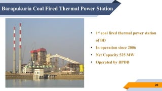
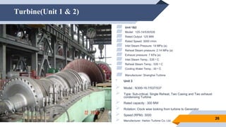
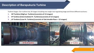
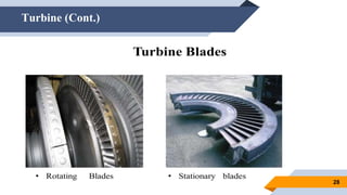
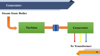
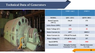
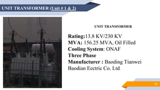
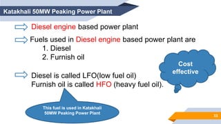
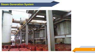
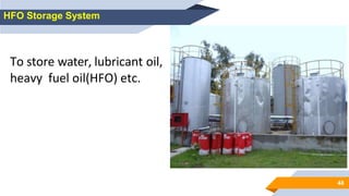
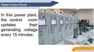
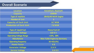
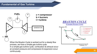
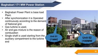
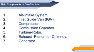
Presented By
Md.Sadat Hasan Bhuiyan
Roll:1601022
Presentation on over all power management Scenario of Bangladesh
& Various Types of Generation-Coal fired, Gas Turbine & HFO
Power plant
1
Course Title:Industrial Training
Course no:EEE 4100
Contents-
2
▰ Introduction
▰ BPDB-Bangladesh Power Development Board
▰ Bangladesh’s Power Management Scenario
▰ Thermal Power Plant( Barapukuria Coal Fired 525 MW)
▰ HFO Power Plant (katakhali 50 MW Peaking )
▰ Gas Power Plant ( Baghabari 71+100 MW )
3
Introduction
Short History Of Power Sector In Bangladesh:
EPWAPDA
Water +
Power
Development
board
1972 PDB
Get separated from
Water development
board
Generation
Transmission
Distribution
EPWAPDA: East Pakistan
Water and Power
Development Authority
PDB: Power Development
Board
BPDB
GENERATION TRANSMISSION DISTRIBUTION
EGCB NWPGCL APSCL PGCB
WZPDCL NWZPDCL DPDC NESCO DESCO BREB
Bangladesh’s Power Management Scenario 2022
4
NLDC
PDB
PDB
Line Diagram of Power System -
5
6
Bangladesh Power Development Board
The Bangladesh Power Development Board (BPDB) is a government agency
operating under the Ministry of Power, Energy and Mineral Resources, Government of
the People's Republic of Bangladesh established in 1972.
Vission:
To Deliver Uninterrupted Quality Power.
Mission:
To secure continuous growth of electricity for sustainable development and
ensure customer satisfaction.
Objectives & Services of BPDB
Objectives-
▰ To be engaged in implementing the development
program of the power sector.
▰ To adopt modern technology and ensure optimum
utilization of fuel.
▰ To purchase power as a Single Buyer from power
producers.
▰ To provide reliable power supply to customers.
▰ To promote a work culture, team spirit and
inventiveness to overcome challenges.
▰ To promote ideas, talent and value systems for
employees.
Nature of services-
▰ Mainly deals with generation.
▰ Observation the proper
transmission & distribution
management through
transmission & distribution
Companies.
▰ BPDB -buys unit of electricity at
higher rate from plants but
sells at lower price for
consumer facility.
7
Basic Classification of Power Plant.
8
Installed Capacity of BPDB Power Plants
(based on fuel) as on April 2022
9
10
Installed Capacity of BPDB Power Plants (based on
different sectors) as on 9th March 2022
Public Sector Number of Power Plant Installed Capacity(MW)
BPDB 38 6013
APSCL 5 1294
EGCB 3 957
NWPGCL 7 1401
B-R Power Gen. 1 149
RPCL 3 182
SubTotal 57 9946MW (44%)
Private , Import & Joint Venture Power Plants-(Running)
.
11
Private No of
Plants
Capacity(
MW)
IPPS 63 8457
SIPPS 4 99
SIPPS 9 251
15 year
rental
4 169
Power
Import
Capacity(
MW)
Bheramara
(HVDC)
1000
Tripura 160
Joint
Venture
No of
plants
Capacity(
MW)
3/5 Year
Rental
12 920
SubTotal 92 9896MW
(46%)
BCPCL 1 1244
Sub total 1 1244MW
(4%)
Sub total 1160MW
( 5%)
Total Capacity 22,296 MW
IPPS=Independent power producer & Supplier
SIPPS=Small Independent Power Producer & Supplier
Future Plan of BPDB
12
When PDB starts its journey in 1992 the installed capacity was only 200MW which
make 3200MW in 2005/2004. Now the installed capacity has a growth about
22787MW, with the increasing amount of demand in Bangladesh the proposed
Generation capacity
Large scale power station planned up to
2035
13
Source : PSMP 2010
Investment Requirement for New Generation,
Transmission & Distribution (High Case)in billion US$
14
Year
Generati
on
Transmissi
on
Distrib
ution
Total
2017-
2025
56 13 12 82
2026-
2030
38 5 7 50
2031-
2035
27 6 7 40
2036-
2041
29 6 9 44
Total
(2017-41)
150 31 35 216
Source: Revisiting Power System Master
Plan (PSMP) 2016
Bangladesh’s electricity mix, 2041 vs. 2018
15
Sub-regional cooperation in the power sector
16
1.Indo-Bangla-Bhutan co-operation in hydroelectric power sought
2.1200MW form The Rampal Power Station( NPTC India)
3.There is a proposed project argument supposed to be introduced
by Nepal- Bangladesh - China
Present Challenge and Development plans
17
Demand and Supply
Matching
Best use of Natural Gases
(Established coal dependent
plants for minimize the pressure
of natural gas crisis)
Introduce Renewable
Energy
Reduce System losses. At presents
system loss is 10.9%, which was
45% in 1992-1993
Increase the efficiency
It was intended by the
government to produce 35%
electricity based on coal in
according to Power System
Master Plan 2016 (PSPM 2016a,
PSPM 2016b)
Step to increase Energy Efficiency
18
Setting Fuel Saving target for energy
efficiency and master plan : 2030- 20%
Provide loan to green industry
Incorporate fuel saving provisions in BNBC
Provide low interest loans in industrial
buildings and residential sector to buy Energy
Efficient Tools
Thermal Power Station
Barapukuria Coal Fired Thermal Power Station
(525MW)
19
Barapukuria Coal Fired Thermal Power Station
20
• 1st coal fired thermal power station
of BD
• In operation since 2006
• Net Capacity 525 MW
• Operated by BPDB
Generating Units & Coal Characteristics
21
Thermal Power Station
22
Heat energy
of coal
combustion
Electrical
energy
23
Characteristics Of Coal
Material %Percentage
Fixed Carbon 48.2
Volatile Matter 29.2
Ash 12.4
Total Moisture 10
Total Sulpher < 0.53
Gross Calorific Value 6200 - 7000 kcal/kg(Approx.)
FLOW DIAGRAM
24
Boiler & Boiler Furnace
25
Fig. Boiler Furnace
Turbine(Unit 1 & 2)
26
▰ Unit 1&2
▰ Model: 125-14/535/535
▰ Rated Output: 125 MW
▰ Rated Speed: 3000 r/min
▰ Inlet Steam Pressure: 14 MPa (a)
▰ Reheat Steam pressure: 2.14 MPa (a)
▰ Exhaust pressure: 7 KPa (a)
▰ Inlet Steam Temp.: 535 ᵒ C
▰ Reheat Steam Temp.: 535 ᵒ C
▰ Cooling Water Temp.: 30 ᵒ C
▰ Manufacturer: Shanghai Turbine Company, Ltd. China
• Unit 3
 Model.: N300-16.7/537/537
 Type: Sub-critical, Single Reheat, Two Casing and Two exhaust
condensing Turbine
 Rated capacity : 300 MW
 Rotation: Clock wise looking from turbine to Generator
 Speed (RPM): 3000
 Manufacturer: Harbin Turbine Co. Ltd.
Description of Barapukuria Turbine
.
27
Turbine (Cont.)
28
Generator-
29
Technical Data of Generators
30
UNIT 1 & 2 UNIT 3
MODEL QFS –125-2 QFSN–300-2
Rated Capacity
(MVA)
156.25 375
Active Power (MW) 125 300
Stator Voltage (kV) 13.8 20
Stator Current (A) 6537 10825.3
Rotor Current (A) 1750 (627No load) 2764
Rotor Voltage (V) 275 (88 No load) 357
Speed (RPM) 3000 3000
Manufacturer Shanghai Turbine
Generator Co. Ltd.
Harbin Generator
Co. Ltd.
31
UNIT TRANSFORMER (Unit # 1 & 2)
UNIT TRANSFORMER
Rating:13.8 KV/230 KV
MVA: 156.25 MVA, Oil Filled
Cooling System: ONAF
Three Phase
Manufacturer : Baoding Tianwei
Baodian Eectric Co. Ltd.
HFO Power Plant
Katakhali 50MW Peaking Power Plant
32
Diesel engine based power plant
Fuels used in Diesel engine based power plant are
1. Diesel
2. Furnish oil
Diesel is called LFO(low fuel oil)
Furnish oil is called HFO (heavy fuel oil).
Cost
effective
Katakhali 50MW Peaking Power Plant
This fuel is used in Katakhali
50MW Peaking Power Plant
33
34
HFO –Heavy Fuel Oil
Components-
88 % Carbon
10% Hydrogen
1% Sulphur
0.5 % H2O
0.1% ash ,
& may contain
dispersed solid or
semisolid particles
35
Basic Principle of Katakhali 50MW PPP
HFO burns inside the engine and products of the combustion act as
the working fluid to produce mechanical energy
Diesel engine drives the alternator which converts mechanical
energy into electrical energy
Chemical
energy of
HFO
Mechanical
energy
Electrical
Energy
Engine Generator
36
Generation Unit-
Engine Alternator
6 diesel engine each of the engine capacity is 8.7 MW
37
Generation Unit (Contd)
38
Generator-
Number of generator 6
Generator apparent power 11,155 KVA
Rated power factor 0.8
Nominal voltage 11 KV
Rated current 585 A
Voltage adjustment range ±5 %
Frequency 50 Hz
Speed 750 rpm
Over speed 900 rpm
Cooling method Air
Generator information
39
Three Phase Step Up Transformer
Bus Bar
40
Circuit Breaker- Circuit
Breaker
Break or make a circuit
under fault conditions.
Protect the electrical
equipment from short circuit
transient current.
41
Isolator
Isolator is a mechanical
switch which isolates a
part of circuit from system
as when required.
Electrical isolators
separate a part of the
system from rest for safe
maintenance works.
42
Current Transformer
Current
Transformer
1. 1.Used for Current Measure
2. 2.Used for protection purpose as well.e
43
Potential Transformer & Lighting Arrestator
Potential
Transformer
Lightning
Arrester
 Used for Measuring Voltage
Used for Thunder Protection
44
Single Line Diagram of Katakhali PPP
45
Auxilary System-
 Engine cooling
 Exhaust gas system
 Charge air system
 Control and monitoring
 Heavy fuel oil supply
 Starting and control air
 Water supply
46
Water Treatment Section
Raw water is
dematerialized in
water treatment unit.
47
Steam Generation System
48
HFO Storage System
To store water, lubricant oil,
heavy fuel oil(HFO) etc.
49
Digital Control Room
In this power plant,
the control room
updates their
generating voltage
every 15 minutes.
50
Overall Scenario
Location Katakhali, Rajshahi
Capacity 50MW
Type of machine 18V32/40 MAN Engine
Number of Unit 6
Capacity of Each Unit 8.7 M W
Production of Each Unit 7.8 M W
Type of Liquid Fuel Heavy Fuel oil
Evacuation Voltage 132 K V
Operating Voltage Range +10%, -20%
Manufacture Man Turbo Engine by Germany
Operating frequency 50 HZ(±3%)
Power Factor 0.8
Generator Voltage 11 K V
Service Voltage 0.4 K V
51
Gas Power Plant-
Baghabari 171 MW Power Station
52
Fundamental of Gas Turbine
AIR
FUEL
GENERATOR
c t
b
c = compressor
b = burners
t = turbine
1
2
3
4
When the Brayton Cycle is worked out for a steady flow
process, we have a simple gas turbine cycle.
In a simple gas turbine cycle, combustion & exhaust occur
at constant pressure and compression & expansion occur
continuously.
53
Baghabari 171 MW Power Station
• Baghabari Power Plant is base load
Plant.
• After synchronization it is Operated
continuously according to the demand
of National grid.
• Gas turbine is used.
• Air and gas mixture is the reason of
combusition
• Single shaft is used starting from the
auxiliary compartment to the turbine
end
Unit 01
(71MW)
Unit 02
(100MW
)
54
Generation Units
55
Main Components of Gas-Turbine
1. Air-Intake System.
2. Inlet Guide Van (IGV).
3. Compressor.
4. Combustion Chamber.
5. Turbine-Rotor.
6. Exhaust- Plenum or Chimney.
7. Generator.
56
Auxiliary Components of GT
1. Air-Filters.
2. Lub-Oil Pump.
3. Turning-Gear.
4. Cranking Motor.
5. Torque Converter.
6. Midst Eliminator.
7. Cooling Water Pump
8. Fin-Fan.
9. GT-Compartment Exhaust Fan.
10. Load Gear Compartment Exhaust Fan.
11. GT-Housing Cooling Fan.
12. Hydraulic Oil Pump.
13. Lift Oil Pump.
14. Compressor Bleed Heating.
57
Inlet Guide Vane (IGV)
Functions
1. To regulate air-flow through Compressor at different conditions of GT.
2. At load condition of GT it follows exhaust temperature. It remains 57% open up to
a preselected exhaust temperature set point.
3. When exhaust temperature reach the set point it starts open further.
4.Thus with the increase of load it keeps on opening to maintain preselected set point. The Load
with full opening (84%) of IGV is called Base-Load.
5. If GT is selected for Peak-Load operation the preselected exhaust temperature set point
shifted to some higher value. Following such higher set value, Load with full opening of IGV is
called Peak-Load.
58
Turning Gear & Cranking Motor
Turning gear function :
Turning gear function is to rotate the gas turbine rotor during start-up, cool down, and when
needed during a maintenance inspection. During cool down, the turning gear system turns the
turbine rotor at about 100 rpm to prevent bowing of the turbine rotor and to protect the turbine
rotor and the unit bearings from thermal damage.
Function of Cranking Motor is to speed up the Turbine Rotor with the help of TC.
Condition to start:
1. Lub-Oil Pressure normal.
2. Hydraulic Oil Pressure normal.
3. Lift Oil Pressure normal.
Cranking Motor
59
Gas Booster. Cooling water pump & Fin-Fan
• a series of mechanical components that boost the pressure of natural gases.
• Gas booster systems are capable of compressing nitrogen.
• It can take the pressure of the gas to 18-24 bar of the gas having 10 bar of pressure originally.
Gas Booster
Cooling water pump & Fin-Fan
Cooling water pump supplies cooling water to different coolers of GT. Fin-Fan cools worm water
return from GT . It is a closed cycle .
De-Mineralized water mixed with proportionate quantity recommended chemical (RD-11) usually
used in this process.
60
Cooling & Sealing Air system
The cooling & sealing air system provides the necessary air flow from the compressor
to the other parts of the gas turbine rotor & stator to prevent excessive temperature
buildup in these parts during normal operation and sealing of the turbine bearings.
Atmospheric air from external centrifugal blowers is also used cool the turbine exhaust
frame.
Cooling & sealing function provided by the system are :
1. Sealing of turbine bearings
2. Cooling the internal turbine parts subjected to high temperature
3. Cooling of the turbine outer shell & exhaust frame
4. Providing an operating air supply for air operated valves
5. Compressor pulsation protection
61
Gas Turbine Maintenance
Classification Gas Turbine Maintenance ;
1. Standby Inspection
2. Running Inspection
3. Dis-assembly Inspection
Dis-assembly Inspection can be classified into :
1. Combustion Inspection
2. Hot Gas Path Inspection
3. Major Inspection
S/N Types of Inspection Interval
01 Combustion Inspection (CI) 8000 running hour or
600 fired start Whichever comes
earlier
02 Hot Gas Path Inspection
(HGPI)
24000 running hour or
1200 fired start Whichever comes
earlier
03 Major Inspection (MI) 48000 running hour or
2400 fired start Whichever comes
earlier
62
Transmission of Generated Power
 Generated Voltage is 11KV.
 Transformer is Delta –Y connected.
 Three individual Transformer act as a single three phase.
 Rating 35MVA (single).
 Convert 11KV/132 KV
63
Line Diagram of Baghabari 170 MW Power Palnt
36
Thank You

PDB-presentation(1).pptx

  • 1.
    Presented By Md.Sadat HasanBhuiyan Roll:1601022 Presentation on over all power management Scenario of Bangladesh & Various Types of Generation-Coal fired, Gas Turbine & HFO Power plant 1 Course Title:Industrial Training Course no:EEE 4100
  • 2.
    Contents- 2 ▰ Introduction ▰ BPDB-BangladeshPower Development Board ▰ Bangladesh’s Power Management Scenario ▰ Thermal Power Plant( Barapukuria Coal Fired 525 MW) ▰ HFO Power Plant (katakhali 50 MW Peaking ) ▰ Gas Power Plant ( Baghabari 71+100 MW )
  • 3.
    3 Introduction Short History OfPower Sector In Bangladesh: EPWAPDA Water + Power Development board 1972 PDB Get separated from Water development board Generation Transmission Distribution EPWAPDA: East Pakistan Water and Power Development Authority PDB: Power Development Board
  • 4.
    BPDB GENERATION TRANSMISSION DISTRIBUTION EGCBNWPGCL APSCL PGCB WZPDCL NWZPDCL DPDC NESCO DESCO BREB Bangladesh’s Power Management Scenario 2022 4 NLDC PDB PDB
  • 5.
    Line Diagram ofPower System - 5
  • 6.
    6 Bangladesh Power DevelopmentBoard The Bangladesh Power Development Board (BPDB) is a government agency operating under the Ministry of Power, Energy and Mineral Resources, Government of the People's Republic of Bangladesh established in 1972. Vission: To Deliver Uninterrupted Quality Power. Mission: To secure continuous growth of electricity for sustainable development and ensure customer satisfaction.
  • 7.
    Objectives & Servicesof BPDB Objectives- ▰ To be engaged in implementing the development program of the power sector. ▰ To adopt modern technology and ensure optimum utilization of fuel. ▰ To purchase power as a Single Buyer from power producers. ▰ To provide reliable power supply to customers. ▰ To promote a work culture, team spirit and inventiveness to overcome challenges. ▰ To promote ideas, talent and value systems for employees. Nature of services- ▰ Mainly deals with generation. ▰ Observation the proper transmission & distribution management through transmission & distribution Companies. ▰ BPDB -buys unit of electricity at higher rate from plants but sells at lower price for consumer facility. 7
  • 8.
  • 9.
    Installed Capacity ofBPDB Power Plants (based on fuel) as on April 2022 9
  • 10.
    10 Installed Capacity ofBPDB Power Plants (based on different sectors) as on 9th March 2022 Public Sector Number of Power Plant Installed Capacity(MW) BPDB 38 6013 APSCL 5 1294 EGCB 3 957 NWPGCL 7 1401 B-R Power Gen. 1 149 RPCL 3 182 SubTotal 57 9946MW (44%)
  • 11.
    Private , Import& Joint Venture Power Plants-(Running) . 11 Private No of Plants Capacity( MW) IPPS 63 8457 SIPPS 4 99 SIPPS 9 251 15 year rental 4 169 Power Import Capacity( MW) Bheramara (HVDC) 1000 Tripura 160 Joint Venture No of plants Capacity( MW) 3/5 Year Rental 12 920 SubTotal 92 9896MW (46%) BCPCL 1 1244 Sub total 1 1244MW (4%) Sub total 1160MW ( 5%) Total Capacity 22,296 MW IPPS=Independent power producer & Supplier SIPPS=Small Independent Power Producer & Supplier
  • 12.
    Future Plan ofBPDB 12 When PDB starts its journey in 1992 the installed capacity was only 200MW which make 3200MW in 2005/2004. Now the installed capacity has a growth about 22787MW, with the increasing amount of demand in Bangladesh the proposed Generation capacity
  • 13.
    Large scale powerstation planned up to 2035 13 Source : PSMP 2010
  • 14.
    Investment Requirement forNew Generation, Transmission & Distribution (High Case)in billion US$ 14 Year Generati on Transmissi on Distrib ution Total 2017- 2025 56 13 12 82 2026- 2030 38 5 7 50 2031- 2035 27 6 7 40 2036- 2041 29 6 9 44 Total (2017-41) 150 31 35 216 Source: Revisiting Power System Master Plan (PSMP) 2016
  • 15.
  • 16.
    Sub-regional cooperation inthe power sector 16 1.Indo-Bangla-Bhutan co-operation in hydroelectric power sought 2.1200MW form The Rampal Power Station( NPTC India) 3.There is a proposed project argument supposed to be introduced by Nepal- Bangladesh - China
  • 17.
    Present Challenge andDevelopment plans 17 Demand and Supply Matching Best use of Natural Gases (Established coal dependent plants for minimize the pressure of natural gas crisis) Introduce Renewable Energy Reduce System losses. At presents system loss is 10.9%, which was 45% in 1992-1993 Increase the efficiency It was intended by the government to produce 35% electricity based on coal in according to Power System Master Plan 2016 (PSPM 2016a, PSPM 2016b)
  • 18.
    Step to increaseEnergy Efficiency 18 Setting Fuel Saving target for energy efficiency and master plan : 2030- 20% Provide loan to green industry Incorporate fuel saving provisions in BNBC Provide low interest loans in industrial buildings and residential sector to buy Energy Efficient Tools
  • 19.
    Thermal Power Station BarapukuriaCoal Fired Thermal Power Station (525MW) 19
  • 20.
    Barapukuria Coal FiredThermal Power Station 20 • 1st coal fired thermal power station of BD • In operation since 2006 • Net Capacity 525 MW • Operated by BPDB
  • 21.
    Generating Units &Coal Characteristics 21
  • 22.
    Thermal Power Station 22 Heatenergy of coal combustion Electrical energy
  • 23.
    23 Characteristics Of Coal Material%Percentage Fixed Carbon 48.2 Volatile Matter 29.2 Ash 12.4 Total Moisture 10 Total Sulpher < 0.53 Gross Calorific Value 6200 - 7000 kcal/kg(Approx.)
  • 24.
  • 25.
    Boiler & BoilerFurnace 25 Fig. Boiler Furnace
  • 26.
    Turbine(Unit 1 &2) 26 ▰ Unit 1&2 ▰ Model: 125-14/535/535 ▰ Rated Output: 125 MW ▰ Rated Speed: 3000 r/min ▰ Inlet Steam Pressure: 14 MPa (a) ▰ Reheat Steam pressure: 2.14 MPa (a) ▰ Exhaust pressure: 7 KPa (a) ▰ Inlet Steam Temp.: 535 ᵒ C ▰ Reheat Steam Temp.: 535 ᵒ C ▰ Cooling Water Temp.: 30 ᵒ C ▰ Manufacturer: Shanghai Turbine Company, Ltd. China • Unit 3  Model.: N300-16.7/537/537  Type: Sub-critical, Single Reheat, Two Casing and Two exhaust condensing Turbine  Rated capacity : 300 MW  Rotation: Clock wise looking from turbine to Generator  Speed (RPM): 3000  Manufacturer: Harbin Turbine Co. Ltd.
  • 27.
  • 28.
  • 29.
  • 30.
    Technical Data ofGenerators 30 UNIT 1 & 2 UNIT 3 MODEL QFS –125-2 QFSN–300-2 Rated Capacity (MVA) 156.25 375 Active Power (MW) 125 300 Stator Voltage (kV) 13.8 20 Stator Current (A) 6537 10825.3 Rotor Current (A) 1750 (627No load) 2764 Rotor Voltage (V) 275 (88 No load) 357 Speed (RPM) 3000 3000 Manufacturer Shanghai Turbine Generator Co. Ltd. Harbin Generator Co. Ltd.
  • 31.
    31 UNIT TRANSFORMER (Unit# 1 & 2) UNIT TRANSFORMER Rating:13.8 KV/230 KV MVA: 156.25 MVA, Oil Filled Cooling System: ONAF Three Phase Manufacturer : Baoding Tianwei Baodian Eectric Co. Ltd.
  • 32.
    HFO Power Plant Katakhali50MW Peaking Power Plant 32
  • 33.
    Diesel engine basedpower plant Fuels used in Diesel engine based power plant are 1. Diesel 2. Furnish oil Diesel is called LFO(low fuel oil) Furnish oil is called HFO (heavy fuel oil). Cost effective Katakhali 50MW Peaking Power Plant This fuel is used in Katakhali 50MW Peaking Power Plant 33
  • 34.
    34 HFO –Heavy FuelOil Components- 88 % Carbon 10% Hydrogen 1% Sulphur 0.5 % H2O 0.1% ash , & may contain dispersed solid or semisolid particles
  • 35.
    35 Basic Principle ofKatakhali 50MW PPP HFO burns inside the engine and products of the combustion act as the working fluid to produce mechanical energy Diesel engine drives the alternator which converts mechanical energy into electrical energy Chemical energy of HFO Mechanical energy Electrical Energy Engine Generator
  • 36.
    36 Generation Unit- Engine Alternator 6diesel engine each of the engine capacity is 8.7 MW
  • 37.
  • 38.
    38 Generator- Number of generator6 Generator apparent power 11,155 KVA Rated power factor 0.8 Nominal voltage 11 KV Rated current 585 A Voltage adjustment range ±5 % Frequency 50 Hz Speed 750 rpm Over speed 900 rpm Cooling method Air Generator information
  • 39.
    39 Three Phase StepUp Transformer Bus Bar
  • 40.
    40 Circuit Breaker- Circuit Breaker Breakor make a circuit under fault conditions. Protect the electrical equipment from short circuit transient current.
  • 41.
    41 Isolator Isolator is amechanical switch which isolates a part of circuit from system as when required. Electrical isolators separate a part of the system from rest for safe maintenance works.
  • 42.
    42 Current Transformer Current Transformer 1. 1.Usedfor Current Measure 2. 2.Used for protection purpose as well.e
  • 43.
    43 Potential Transformer &Lighting Arrestator Potential Transformer Lightning Arrester  Used for Measuring Voltage Used for Thunder Protection
  • 44.
    44 Single Line Diagramof Katakhali PPP
  • 45.
    45 Auxilary System-  Enginecooling  Exhaust gas system  Charge air system  Control and monitoring  Heavy fuel oil supply  Starting and control air  Water supply
  • 46.
    46 Water Treatment Section Rawwater is dematerialized in water treatment unit.
  • 47.
  • 48.
    48 HFO Storage System Tostore water, lubricant oil, heavy fuel oil(HFO) etc.
  • 49.
    49 Digital Control Room Inthis power plant, the control room updates their generating voltage every 15 minutes.
  • 50.
    50 Overall Scenario Location Katakhali,Rajshahi Capacity 50MW Type of machine 18V32/40 MAN Engine Number of Unit 6 Capacity of Each Unit 8.7 M W Production of Each Unit 7.8 M W Type of Liquid Fuel Heavy Fuel oil Evacuation Voltage 132 K V Operating Voltage Range +10%, -20% Manufacture Man Turbo Engine by Germany Operating frequency 50 HZ(±3%) Power Factor 0.8 Generator Voltage 11 K V Service Voltage 0.4 K V
  • 51.
    51 Gas Power Plant- Baghabari171 MW Power Station
  • 52.
    52 Fundamental of GasTurbine AIR FUEL GENERATOR c t b c = compressor b = burners t = turbine 1 2 3 4 When the Brayton Cycle is worked out for a steady flow process, we have a simple gas turbine cycle. In a simple gas turbine cycle, combustion & exhaust occur at constant pressure and compression & expansion occur continuously.
  • 53.
    53 Baghabari 171 MWPower Station • Baghabari Power Plant is base load Plant. • After synchronization it is Operated continuously according to the demand of National grid. • Gas turbine is used. • Air and gas mixture is the reason of combusition • Single shaft is used starting from the auxiliary compartment to the turbine end Unit 01 (71MW) Unit 02 (100MW )
  • 54.
  • 55.
    55 Main Components ofGas-Turbine 1. Air-Intake System. 2. Inlet Guide Van (IGV). 3. Compressor. 4. Combustion Chamber. 5. Turbine-Rotor. 6. Exhaust- Plenum or Chimney. 7. Generator.
  • 56.
    56 Auxiliary Components ofGT 1. Air-Filters. 2. Lub-Oil Pump. 3. Turning-Gear. 4. Cranking Motor. 5. Torque Converter. 6. Midst Eliminator. 7. Cooling Water Pump 8. Fin-Fan. 9. GT-Compartment Exhaust Fan. 10. Load Gear Compartment Exhaust Fan. 11. GT-Housing Cooling Fan. 12. Hydraulic Oil Pump. 13. Lift Oil Pump. 14. Compressor Bleed Heating.
  • 57.
    57 Inlet Guide Vane(IGV) Functions 1. To regulate air-flow through Compressor at different conditions of GT. 2. At load condition of GT it follows exhaust temperature. It remains 57% open up to a preselected exhaust temperature set point. 3. When exhaust temperature reach the set point it starts open further. 4.Thus with the increase of load it keeps on opening to maintain preselected set point. The Load with full opening (84%) of IGV is called Base-Load. 5. If GT is selected for Peak-Load operation the preselected exhaust temperature set point shifted to some higher value. Following such higher set value, Load with full opening of IGV is called Peak-Load.
  • 58.
    58 Turning Gear &Cranking Motor Turning gear function : Turning gear function is to rotate the gas turbine rotor during start-up, cool down, and when needed during a maintenance inspection. During cool down, the turning gear system turns the turbine rotor at about 100 rpm to prevent bowing of the turbine rotor and to protect the turbine rotor and the unit bearings from thermal damage. Function of Cranking Motor is to speed up the Turbine Rotor with the help of TC. Condition to start: 1. Lub-Oil Pressure normal. 2. Hydraulic Oil Pressure normal. 3. Lift Oil Pressure normal. Cranking Motor
  • 59.
    59 Gas Booster. Coolingwater pump & Fin-Fan • a series of mechanical components that boost the pressure of natural gases. • Gas booster systems are capable of compressing nitrogen. • It can take the pressure of the gas to 18-24 bar of the gas having 10 bar of pressure originally. Gas Booster Cooling water pump & Fin-Fan Cooling water pump supplies cooling water to different coolers of GT. Fin-Fan cools worm water return from GT . It is a closed cycle . De-Mineralized water mixed with proportionate quantity recommended chemical (RD-11) usually used in this process.
  • 60.
    60 Cooling & SealingAir system The cooling & sealing air system provides the necessary air flow from the compressor to the other parts of the gas turbine rotor & stator to prevent excessive temperature buildup in these parts during normal operation and sealing of the turbine bearings. Atmospheric air from external centrifugal blowers is also used cool the turbine exhaust frame. Cooling & sealing function provided by the system are : 1. Sealing of turbine bearings 2. Cooling the internal turbine parts subjected to high temperature 3. Cooling of the turbine outer shell & exhaust frame 4. Providing an operating air supply for air operated valves 5. Compressor pulsation protection
  • 61.
    61 Gas Turbine Maintenance ClassificationGas Turbine Maintenance ; 1. Standby Inspection 2. Running Inspection 3. Dis-assembly Inspection Dis-assembly Inspection can be classified into : 1. Combustion Inspection 2. Hot Gas Path Inspection 3. Major Inspection S/N Types of Inspection Interval 01 Combustion Inspection (CI) 8000 running hour or 600 fired start Whichever comes earlier 02 Hot Gas Path Inspection (HGPI) 24000 running hour or 1200 fired start Whichever comes earlier 03 Major Inspection (MI) 48000 running hour or 2400 fired start Whichever comes earlier
  • 62.
    62 Transmission of GeneratedPower  Generated Voltage is 11KV.  Transformer is Delta –Y connected.  Three individual Transformer act as a single three phase.  Rating 35MVA (single).  Convert 11KV/132 KV
  • 63.
    63 Line Diagram ofBaghabari 170 MW Power Palnt
  • 64.