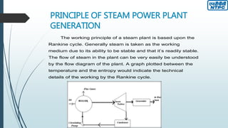
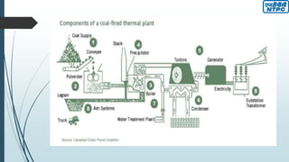
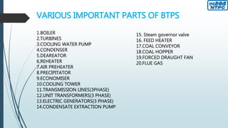
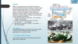
NATIONAL THERMAL
POWER CORPORATION
BADARPUR
INDUSTRIAL TRAINING
ADITYA SHEKHAR
B.TECH 4th YEAR (ELECTRICAL AND ELECTRONICS ENGINEERING),VIET
INTRODUCTION
NTPC Limited is the largest thermal power generating company
of India. A public sector company, it was incorporated in the
year 1975 to accelerate power development in the country as a
wholly owned company of the Government of India. At present,
Government of India holds 89.5% of the total equity shares of
the company and the balance 10.5% is held by FIIs, Domestic
Banks, Public and other. Within a span of 32 years, NTPC has
emerged as a truly national power company, with power
generating facilities in all the major regions of the country.
BACKGROUND
 BADARPUR THERMAL POWER STATION was established on 1973 and it was the part of Central
Government.
 On 01/04/1978 is was given to NTPC.
 Since then operating performance of NTPC has been considerably above the national average.
 Badarpur thermal power station started with a single 95 mw unit.
 There were 2 more units (95 MW each) installed in next 2 consecutive years.
 Now it has total five units with total capacity of 720 MW. Ownership of BTPS was transferred to NTPC
with effect from 01.06.2006
 The power is supplied to a 220 KV network that is a part of the northern grid.
 The ten circuits through which the power is evacuated from the plant are:
o 1. Mehrauli
o 2. Okhla
o 3. Ballabgarh
o 4. Indraprastha
o 5. UP (Noida)
o 6. Jaipur
Installed Capacity
PRINCIPLE OF STEAM POWER PLANT
GENERATION
The working principle of a steam plant is based upon the
Rankine cycle. Generally steam is taken as the working
medium due to its ability to be stable and that it’s readily stable.
The flow of steam in the plant can be very easily be understood
by the flow diagram of the plant. A graph plotted between the
temperature and the entropy would indicate the technical
details of the working by the Rankine cycle.
Plant Flow Diagram(Modified Rankine Cycle)
AB- Heating of feed water (i.e. sensible heat addition)
BC- Evaporation of water in boiler (i.e. latent heat addition)
CD- Superheating of steam (i.e. heat addition)
DE- Isentropic expansion of steam in HP turbine
EF- Reheating of steam in Reheaters
FH- Isentropic expansion of steam in IP and LP turbine
VARIOUS IMPORTANT PARTS OF BTPS
1.BOILER
2.TURBINES
3.COOLING WATER PUMP
4.CONDENSER
5.DEAREATOR
6.REHEATER
7.AIR PREHEATER
8.PRECIPITATOR
9.ECONOMISER
10.COOLING TOWER
11.TRANSMISSION LINES(3PHASE)
12.UNIT TRANSFORMERS(3 PHASE)
13.ELECTRIC GENERATORS(3 PHASE)
14.CONDENSATE EXTRACTION PUMP
15. Steam governor valve
16. FEED HEATER
17.COAL CONVEYOR
18.COAL HOPPER
19.FORCED DRAUGHT FAN
20.FLUE GAS
1.Boiler
Boiler is a rectangular furnace about 50 feet on
side and 130 feet tall. theirs walls are made of high
pressure steel tubes about 2.3 inches in diameter
which circulates DM water to be converted into
steam. The thermal radiation heats water and
changes to steam. Steam is sent to the turbine .The
efficiency and technology of boiler vary according
to the operational pressures.
1. Operational pressure>221 KSC---%n=42.45%---
--super critical boiler
2. 175KSC <Operational pressure<221 KSC---
%n=38.42%----- critical boiler
3. Operational pressure<175KSC---%n=38%-----
sub critical boiler
The turbine generator consists of a series of steam
turbines interconnected to each other and
generators on a common shaft.
2.Turbines
3.Cooling water pumps
It pumps the water from the cooling tower which
goes to the condenser.
4.Condenser
The steam coming out from the Low Pressure
Turbine (a little above its boiling pump) is
brought into thermal contact with cold water
(pumped in from the cooling tower) in the
condenser, where it condenses rapidly back
into water, creating near Vacuum-like
conditions inside the condenser chest.
5.Deareator
A deareator is a device for air removal and
used to remove dissolved gases (an alternate
would be the use of water treatment
chemicals) from boiler feed water to make it
noncorrosive.
6.Reheater
Reheater is a heater which is used to raise
the temperature of steam which has fallen
from the intermediate pressure turbine.
7.Air preheater
The purpose of the air preheater is to recover
the heat from the boiler flue gas which
increases the thermal efficiency of the boiler
by reducing the useful heat lost in the flue
gas.
8.Precipitator
An Electrostatic precipitator (ESP) is a particulate
device that removes particles from a flowing gas
(such as air) using the force of an induced
electrostatic charge.
ELECTRICAL MAINTENANCE DEPARTMENT – I (EMD-I)
It includes:
 Motors
 High Tension/Low Tension Switchgear
 Coal handling plant
MOTORS
AC MOTORS
 Squirrel cage motor
 Wound motor
 Slip ring induction motor
In modern thermal power plant three phase squirrel cage induction
motors are used but sometime double wound motor is used when
we need high starting torque e.g. in ball mill.
SWITCH GEAR
 Switchgear is one that makes or breaks the electrical circuit.
 It is a switching device that opens & closes a circuit that
defined as apparatus used for switching, Lon rolling &
protecting the electrical circuit & equipments.
 The switchgear equipment is essentially concerned with
switching & interrupting currents either under normal or
abnormal operating conditions.
 The tubular switch with ordinary fuse is simplest form of
switchgear & is used to control & protect& other
equipments in homes, offices etc.
 For circuits of higher ratings, a High Rupturing Capacity
(H.R.C) fuse in condition with a switch may serve the
purpose of controlling & protecting the circuit.
COAL HANDLING
The fuel used in the thermal power plants in the boiler
furnace is coal. Coal undergoes various processes like
separation, crushing, etc and is then finally moved to the
furnace in the form of pulverised coal.
Coal: It is a mixture of organic chemicals and mineral materials
produced by natural process of growth and decay. The
chemical properties of any coal depend upon the proportions of
different chemicals components present in it. There are four
types of coal:
1. Peat
2. Lignite
3. Bituminous Coal
4. Anthracite
ELECTRICAL MAINTENANCE DEPARTMENT –II
(EMD-II)
It includes:
 Generators
 Transformers
 Switch yard
GENERATORS
 The generator works on the principle of electromagnetic
induction. There are two components stator and rotor. The
rotor is the moving part and the stator is the stationary
part. The rotor, which has a field winding, is given
a excitation through a set of 3000rpm to give the required
frequency of HZ. The rotor is cooled by Hydrogen gas,
which is locally manufactured by the plant and has high
heat carrying capacity of low density. If oxygen and
hydrogen get mixed then they will form very high explosive
and to prevent their combining in any way there is seal oil
system. The stator cooling is done by de-mineralized (DM)
water through hollow conductors. Water is fed by one end
by Teflon tube. A boiler and a turbine are coupled to
electric generators. Steam from the boiler is fed to the
turbine through the connecting pipe. Steam drives the
turbine rotor. The turbine rotor drives the generator rotor
which turns the electromagnet within the coil of wire
conductors.
 Carbon dioxide is provided from the top and oil is provided
from bottom to the generator. With the help of carbon
dioxide the oil is drained out to the oil tank.
RATINGS OF THE GENERATORS USED
 Turbo generator 100MW
 TURBO GENERATOR 210 MW
 The 100 MW generator generates 10.75 KV and 210 MW generates
15.75 KV. The voltage is stepped up to 220 KV with the help of
generator transformer and is connected to the grid.
 The voltage is stepped down to 6.6 KV with the help of UNIT
AUXILLARY TRANSFORMER (UAT) and this voltage is used to drive
the HT motors. The voltage is further stepped down to 415 V and
then to 220 V and this voltage is used to drive Lt Motors.
TRANSFORMERS
It is a static machine which increases or decreases the AC voltage
without changing the frequency of the supply.
It is a device that:
 Transfer electric power from one circuit to another.
 It accomplishes this by electromagnetic induction.
 In this the two electric circuits are in mutual inductive influence
of each other.
 WORKING PRINCIPLE:
It works on FARADAY’S LAW OF ELECTROMAGNETIC
INDUCTION (self or mutual induction depending on the type of
transformer).
MAIN PARTS OF TRANSFORMER
1. Secondary Winding
2. Primary Winding.
3. Oil Level
4. Conservator
5. Breather
6. Drain Cock
7. Cooling Tubes.
8. Transformer Oil.
9. Earth Point
10. Explosion Vent
11. Temperature Gauge.
12. Buchholz Relay
13. Secondary Terminal
14. Primary Terminal
SWITCH YARD
As we know that electrical energy can’t be stored like cells, so what we generate should be consumed
instantaneously. But as the load is not constants therefore we generate electricity according to need i.e. the
generation depends upon load. The yard is the places from where the electricity is send outside. It has
both outdoor and indoor equipments.
OUTDOOR EQUIPMENTS
 BUS BAR.
 LIGHTENING ARRESTER
 WAVE TRAP
 BREAKER
 CAPACITATIVE VOLTAGE TRANSFORMER
 EARTHING ROD
 CURRENT TRANSFORMER.
 POTENTIAL TRANSFORMER
 LIGHTENING MASK
INDOOR EQUIPMENTS
 RELAYS.
 CONTROL PANELS
 CIRCUIT BREAKERS
THANK YOU

NTPC Badarpur Industrial Training Report

  • 1.
    NATIONAL THERMAL POWER CORPORATION BADARPUR INDUSTRIALTRAINING ADITYA SHEKHAR B.TECH 4th YEAR (ELECTRICAL AND ELECTRONICS ENGINEERING),VIET
  • 2.
    INTRODUCTION NTPC Limited isthe largest thermal power generating company of India. A public sector company, it was incorporated in the year 1975 to accelerate power development in the country as a wholly owned company of the Government of India. At present, Government of India holds 89.5% of the total equity shares of the company and the balance 10.5% is held by FIIs, Domestic Banks, Public and other. Within a span of 32 years, NTPC has emerged as a truly national power company, with power generating facilities in all the major regions of the country.
  • 3.
    BACKGROUND  BADARPUR THERMALPOWER STATION was established on 1973 and it was the part of Central Government.  On 01/04/1978 is was given to NTPC.  Since then operating performance of NTPC has been considerably above the national average.  Badarpur thermal power station started with a single 95 mw unit.  There were 2 more units (95 MW each) installed in next 2 consecutive years.  Now it has total five units with total capacity of 720 MW. Ownership of BTPS was transferred to NTPC with effect from 01.06.2006  The power is supplied to a 220 KV network that is a part of the northern grid.  The ten circuits through which the power is evacuated from the plant are: o 1. Mehrauli o 2. Okhla o 3. Ballabgarh o 4. Indraprastha o 5. UP (Noida) o 6. Jaipur
  • 4.
  • 5.
    PRINCIPLE OF STEAMPOWER PLANT GENERATION The working principle of a steam plant is based upon the Rankine cycle. Generally steam is taken as the working medium due to its ability to be stable and that it’s readily stable. The flow of steam in the plant can be very easily be understood by the flow diagram of the plant. A graph plotted between the temperature and the entropy would indicate the technical details of the working by the Rankine cycle.
  • 7.
    Plant Flow Diagram(ModifiedRankine Cycle) AB- Heating of feed water (i.e. sensible heat addition) BC- Evaporation of water in boiler (i.e. latent heat addition) CD- Superheating of steam (i.e. heat addition) DE- Isentropic expansion of steam in HP turbine EF- Reheating of steam in Reheaters FH- Isentropic expansion of steam in IP and LP turbine
  • 8.
    VARIOUS IMPORTANT PARTSOF BTPS 1.BOILER 2.TURBINES 3.COOLING WATER PUMP 4.CONDENSER 5.DEAREATOR 6.REHEATER 7.AIR PREHEATER 8.PRECIPITATOR 9.ECONOMISER 10.COOLING TOWER 11.TRANSMISSION LINES(3PHASE) 12.UNIT TRANSFORMERS(3 PHASE) 13.ELECTRIC GENERATORS(3 PHASE) 14.CONDENSATE EXTRACTION PUMP 15. Steam governor valve 16. FEED HEATER 17.COAL CONVEYOR 18.COAL HOPPER 19.FORCED DRAUGHT FAN 20.FLUE GAS
  • 9.
    1.Boiler Boiler is arectangular furnace about 50 feet on side and 130 feet tall. theirs walls are made of high pressure steel tubes about 2.3 inches in diameter which circulates DM water to be converted into steam. The thermal radiation heats water and changes to steam. Steam is sent to the turbine .The efficiency and technology of boiler vary according to the operational pressures. 1. Operational pressure>221 KSC---%n=42.45%--- --super critical boiler 2. 175KSC <Operational pressure<221 KSC--- %n=38.42%----- critical boiler 3. Operational pressure<175KSC---%n=38%----- sub critical boiler The turbine generator consists of a series of steam turbines interconnected to each other and generators on a common shaft. 2.Turbines 3.Cooling water pumps It pumps the water from the cooling tower which goes to the condenser.
  • 10.
    4.Condenser The steam comingout from the Low Pressure Turbine (a little above its boiling pump) is brought into thermal contact with cold water (pumped in from the cooling tower) in the condenser, where it condenses rapidly back into water, creating near Vacuum-like conditions inside the condenser chest. 5.Deareator A deareator is a device for air removal and used to remove dissolved gases (an alternate would be the use of water treatment chemicals) from boiler feed water to make it noncorrosive.
  • 11.
    6.Reheater Reheater is aheater which is used to raise the temperature of steam which has fallen from the intermediate pressure turbine. 7.Air preheater The purpose of the air preheater is to recover the heat from the boiler flue gas which increases the thermal efficiency of the boiler by reducing the useful heat lost in the flue gas. 8.Precipitator An Electrostatic precipitator (ESP) is a particulate device that removes particles from a flowing gas (such as air) using the force of an induced electrostatic charge.
  • 12.
    ELECTRICAL MAINTENANCE DEPARTMENT– I (EMD-I) It includes:  Motors  High Tension/Low Tension Switchgear  Coal handling plant
  • 13.
    MOTORS AC MOTORS  Squirrelcage motor  Wound motor  Slip ring induction motor In modern thermal power plant three phase squirrel cage induction motors are used but sometime double wound motor is used when we need high starting torque e.g. in ball mill.
  • 14.
    SWITCH GEAR  Switchgearis one that makes or breaks the electrical circuit.  It is a switching device that opens & closes a circuit that defined as apparatus used for switching, Lon rolling & protecting the electrical circuit & equipments.  The switchgear equipment is essentially concerned with switching & interrupting currents either under normal or abnormal operating conditions.  The tubular switch with ordinary fuse is simplest form of switchgear & is used to control & protect& other equipments in homes, offices etc.  For circuits of higher ratings, a High Rupturing Capacity (H.R.C) fuse in condition with a switch may serve the purpose of controlling & protecting the circuit.
  • 15.
    COAL HANDLING The fuelused in the thermal power plants in the boiler furnace is coal. Coal undergoes various processes like separation, crushing, etc and is then finally moved to the furnace in the form of pulverised coal. Coal: It is a mixture of organic chemicals and mineral materials produced by natural process of growth and decay. The chemical properties of any coal depend upon the proportions of different chemicals components present in it. There are four types of coal: 1. Peat 2. Lignite 3. Bituminous Coal 4. Anthracite
  • 16.
    ELECTRICAL MAINTENANCE DEPARTMENT–II (EMD-II) It includes:  Generators  Transformers  Switch yard
  • 17.
    GENERATORS  The generatorworks on the principle of electromagnetic induction. There are two components stator and rotor. The rotor is the moving part and the stator is the stationary part. The rotor, which has a field winding, is given a excitation through a set of 3000rpm to give the required frequency of HZ. The rotor is cooled by Hydrogen gas, which is locally manufactured by the plant and has high heat carrying capacity of low density. If oxygen and hydrogen get mixed then they will form very high explosive and to prevent their combining in any way there is seal oil system. The stator cooling is done by de-mineralized (DM) water through hollow conductors. Water is fed by one end by Teflon tube. A boiler and a turbine are coupled to electric generators. Steam from the boiler is fed to the turbine through the connecting pipe. Steam drives the turbine rotor. The turbine rotor drives the generator rotor which turns the electromagnet within the coil of wire conductors.  Carbon dioxide is provided from the top and oil is provided from bottom to the generator. With the help of carbon dioxide the oil is drained out to the oil tank.
  • 18.
    RATINGS OF THEGENERATORS USED  Turbo generator 100MW  TURBO GENERATOR 210 MW  The 100 MW generator generates 10.75 KV and 210 MW generates 15.75 KV. The voltage is stepped up to 220 KV with the help of generator transformer and is connected to the grid.  The voltage is stepped down to 6.6 KV with the help of UNIT AUXILLARY TRANSFORMER (UAT) and this voltage is used to drive the HT motors. The voltage is further stepped down to 415 V and then to 220 V and this voltage is used to drive Lt Motors.
  • 19.
    TRANSFORMERS It is astatic machine which increases or decreases the AC voltage without changing the frequency of the supply. It is a device that:  Transfer electric power from one circuit to another.  It accomplishes this by electromagnetic induction.  In this the two electric circuits are in mutual inductive influence of each other.  WORKING PRINCIPLE: It works on FARADAY’S LAW OF ELECTROMAGNETIC INDUCTION (self or mutual induction depending on the type of transformer).
  • 20.
    MAIN PARTS OFTRANSFORMER 1. Secondary Winding 2. Primary Winding. 3. Oil Level 4. Conservator 5. Breather 6. Drain Cock 7. Cooling Tubes. 8. Transformer Oil. 9. Earth Point 10. Explosion Vent 11. Temperature Gauge. 12. Buchholz Relay 13. Secondary Terminal 14. Primary Terminal
  • 21.
    SWITCH YARD As weknow that electrical energy can’t be stored like cells, so what we generate should be consumed instantaneously. But as the load is not constants therefore we generate electricity according to need i.e. the generation depends upon load. The yard is the places from where the electricity is send outside. It has both outdoor and indoor equipments. OUTDOOR EQUIPMENTS  BUS BAR.  LIGHTENING ARRESTER  WAVE TRAP  BREAKER  CAPACITATIVE VOLTAGE TRANSFORMER  EARTHING ROD  CURRENT TRANSFORMER.  POTENTIAL TRANSFORMER  LIGHTENING MASK INDOOR EQUIPMENTS  RELAYS.  CONTROL PANELS  CIRCUIT BREAKERS
  • 22.