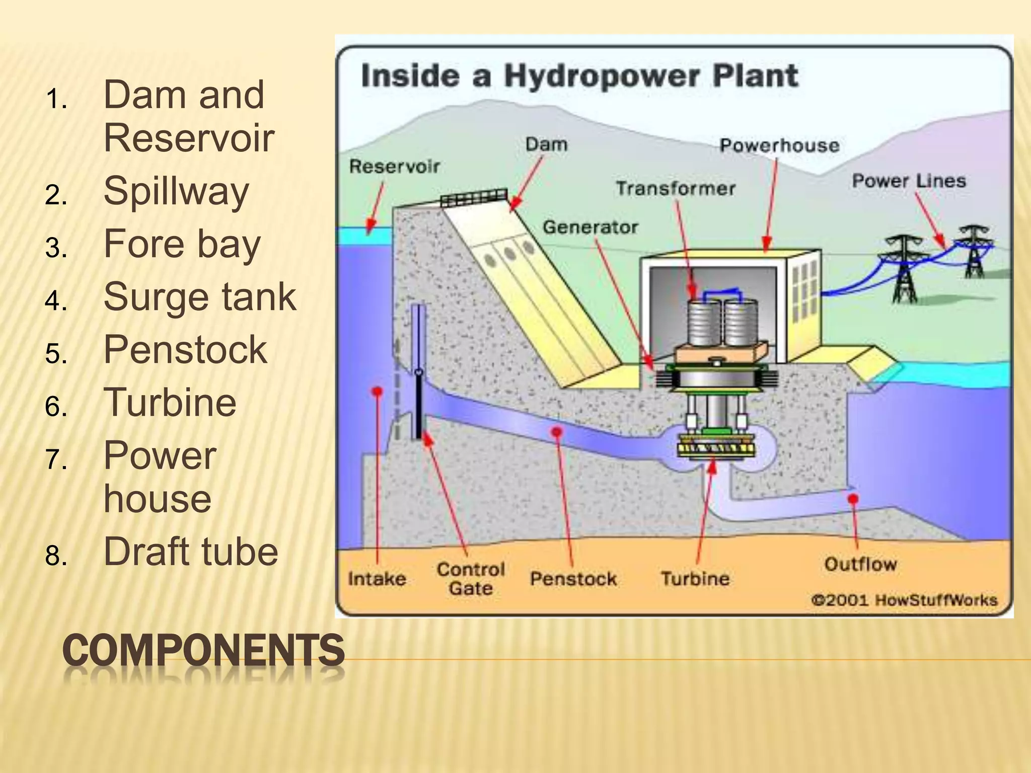
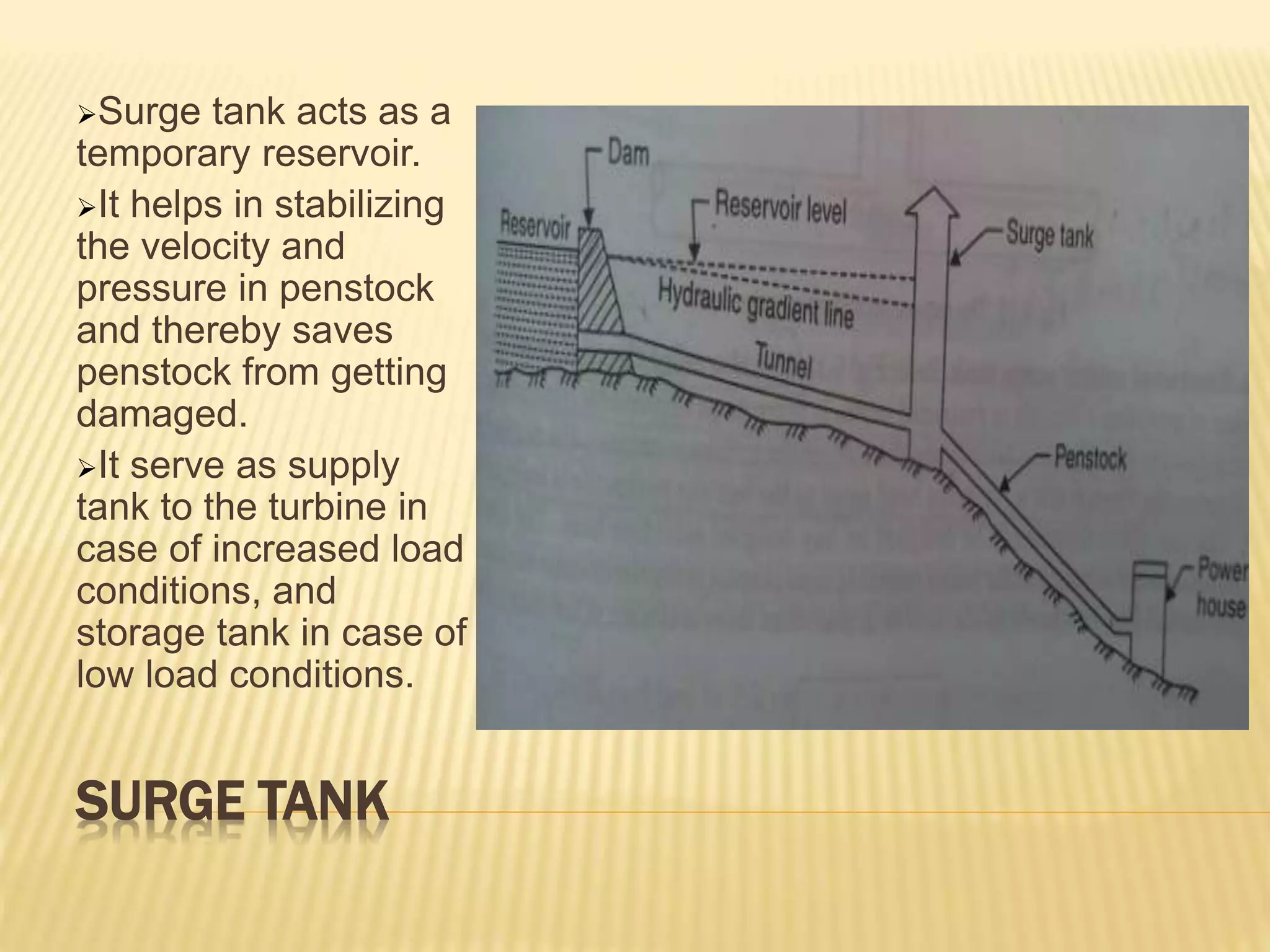
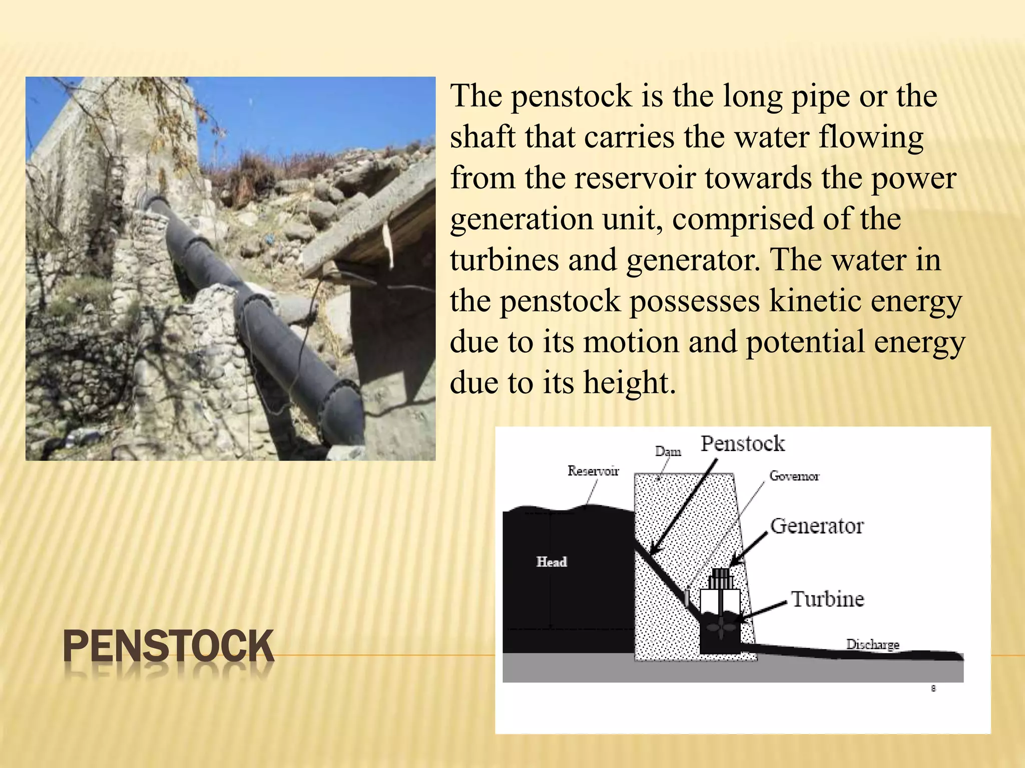
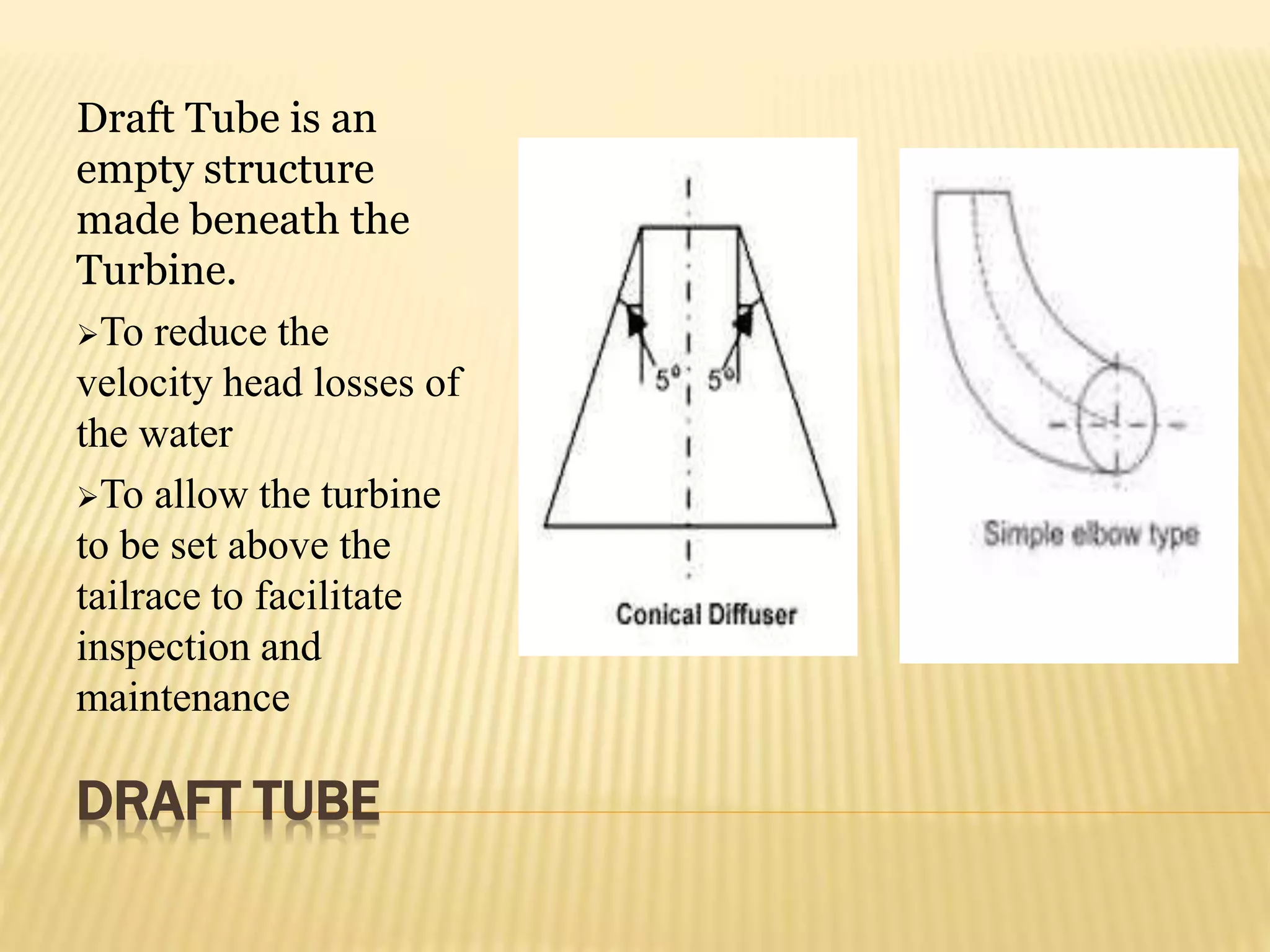
This document provides an overview of a seminar on hydro power plants. It discusses key components of hydro power plants like dams, reservoirs, penstocks and turbines. It also classifies hydro power plants based on factors like water availability and head. Additionally, it compares hydro power to thermal and nuclear plants and briefly describes some major dams in India like Jawahar Sagar, Rana Pratap Sagar and Mahi Bajaj. The conclusion emphasizes the need to fully utilize India's untapped small hydro power potential to meet the country's energy demands.
2. CONTENTS
1. Introduction
2. Site selection
3. Components
4. Classification of hydro power plant
5. Comparison of Hydro and Thermal and
Nuclear power plant
6. A brief on major dams
7. Conclusions
3. INTRODUCTION
In hydroelectric power station kinetic energy of
stored water is converted into electric energy .
30% of the total power in world is provided by hydro
power plant.
The world’s hydro power potential is about 2724
MkW
Total hydro power potential of India is 84 MkW and
22% of this potential is being tapped by various
existing and ongoing power schemes.
In India 25.32% of total electricity generation capacity is
produced by hydro power plant.
4. SITE SELECTION FOR A HYDRO POWER PLANT
Availability of water
Water storage
Water head
Accessibility of site
Distance from the load centre
Geological characteristics of site
6. DAM AND RESERVOIR
An open-air storage area usually formed by masonry or
earthwork where water is collected and kept in quantity so
that it may be drawn off for use.
The water reservoir is the place behind the dam where
water is stored.
The water in the reservoir is located higher than the rest of
the dam structure.
The height of water in the reservoir decides how much
potential energy the water
The higher the height of water, the more its potential energy.
The high position of water in the reservoir also enables it to
move downwards effortlessly.
7. SPILLWAY
Spillway is
constructed to act as
a safety valve. It
discharge the
overflow water to the
down stream side
when the reservoir is
full. These are
generally
constructed of
concrete and
provided with water
discharge opening.
8. SURGE TANK
Surge tank acts as a
temporary reservoir.
It helps in stabilizing
the velocity and
pressure in penstock
and thereby saves
penstock from getting
damaged.
It serve as supply
tank to the turbine in
case of increased load
conditions, and
storage tank in case of
low load conditions.
9. PENSTOCK
The penstock is the long pipe or the
shaft that carries the water flowing
from the reservoir towards the power
generation unit, comprised of the
turbines and generator. The water in
the penstock possesses kinetic energy
due to its motion and potential energy
due to its height.
10. POWER HOUSE
A power house usually contains following
components:
Hydraulic turbines
Electric generators
Governors
Water circulation pumps
Air ducts
Switch board and instruments
Storage batteries
Cranes
11. TURBINE
Impulse turbine
converts the energy
of fluid in the form of
pressure and
reaction turbine
converts the energy
by reaction on rotor
blades, when the
fluid undergoes a
change in
momentum.
13. DRAFT TUBE
Draft Tube is an
empty structure
made beneath the
Turbine.
To reduce the
velocity head losses of
the water
To allow the turbine
to be set above the
tailrace to facilitate
inspection and
maintenance
14. CLASSIFICATION
1. According to quantity of water
2. According to availability of water head
3. According to load characteristics
4. According to plant capacity
5. According to type of fall
15. ACCORDING TO QUANTITY OF WATER
1.Run of river plant
Water is diverted from the river, routed through the water.
conductor system and finally water after generation of
power is thrown back to the river at a lower level on down
stream.
Power generation fluctuates with the river flow and the firm
power is considerably low.
2.Storage plant
It increases firm power and total power generation by
regulating the flow.
Providing storage is complicated and costly as it involves
construction of dam.
16. ACCORDING TO QUANTITY OF WATER(CONT.)
3. Pumped storage plant
Pump storage projects involve reversible turbines, which
can generate power from water of upper reservoir during
peak hours and pump back water from lower reservoir to
the upper reservoir during off peak hours.
4. Tidal plant
A tidal power plant makes use of the daily rise and fall of
ocean water due to tides.
Tidal power is extracted from the Earth's oceanic tides.
17. ACCORDING TO AVAILABILITY OF WATER HEAD
1. Low head plant
Head –upto 30m.
A sideway stream diverges from the river at the dam.
Vertical shaft Francis or Kaplan turbine are used commonly.
2. Medium head plant
Head -30-70 m
Uses Francis Turbine.
Water is carried in open canals from main reservoir to forebay then
to powerhouse through penstock.
3. High head plants
Head- 71-500 m
Water is stored in the lake over the mountain during high rainy
season or when snow melts.
Pelton Wheel turbine is used.
18. ACCORDING TO PLANT CAPACITY
1. Micro hydel plants
A micro hydel plant has the capacity less than 5 MW.
2. Medium capacity plants
A medium capacity plant has the capacity between 5MW
and 100 MW.
3. High capacity plants
A plant having a capacity between 101 MW and 1000
MW is usually classified as a high capacity plant.
4. Super hydro plants
A super hydro plant has a capacity greater than 1000
MW.
19. ACCORDING TO LOAD CHARACTERISTICS
1. Base load plants
They cater to the base load of the system, they need to
supply constant power when connected to the grid.
2. Peak load plants
Some of the plants supply average load but also some peak
load. Other peak load plants are required to work only
during peak load hours.
21. JAWAHAR SAGAR
The concrete gravity dam.
Power generation is 99 MW(With three units
of 33MW capacity each)
Francis-type turbine is used.
height - 45m and
Length - 393m
22. RANA PRATAP SAGAR
It is a gravity masonry dam.
Construction began1953, Opening date1970
Construction cost Rs. 4065 million
Height- 53.8 meters (177 ft)
Length1,143 meters (3,750 ft)
power generation is 172 MW (with four units
of 43 MW capacity each)
Total capacity2,898 million cubic meters
23. MAHI BAJAJ
Power generation 140MW (2*25+2*45)
Construction began 1972
Opening date 1983
Type of dam-Masonry with embankment main
sections
Impounds Mahi River
Height-43 m (141 ft)
Length-3,062 m (10,046 ft)
Francis-type turbine is used
24. CONCLUSION
In order to achieve a growth rate of 7-8 % as
envisaged in National policy of India, it is also
required to tap all the small Hydro Power
potential of the country.
The utilization of small Hydro Power Potential is
especially required in all states where the
utilized potential is very low like in MP and
therefore optimum utilization of the same may
set up an stepping up stone for achieving self
sufficiency in power sector in country.